Tài liệu GSM Switching, Services and Protocols P2 pdf
Bạn đang xem bản rút gọn của tài liệu. Xem và tải ngay bản đầy đủ của tài liệu tại đây (447.3 KB, 20 trang )
The Mobile Radio Channel
and the Cellular Principle
Many measures, functions and protocols in digital mobile radio networks are based on the
properties of the radio channel and its speci®c qualities in contrast to information trans-
mission through guided media. For the understanding of digital mobile radio networks it is
therefore absolutely necessary to know a few related basic principles. For this reason, the
most important fundamentals of the radio channel and of cellular and transmission tech-
nology will be presented and brie¯y explained in the following. For a more detailed
treatment, see the extensive literature [4,42,50,64].
2.1 Characteristics of the Mobile Radio Channel
The electromagnetic wave of the radio signal propagates under ideal conditions in free
space in a radial-symmetric pattern, i.e. the received power P
Ef
, decreases with the square
of the distance L from the transmitter:
P
Ef
,
1
L
2
These idealized conditions do not apply in terrestrial mobile radio. The signal is scattered
and re¯ected, for example, at natural obstacles like mountains, vegetation, or water
surfaces. The direct and re¯ected signal components are then superimposed at the receiver.
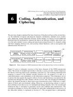
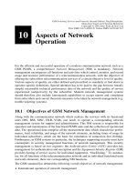
This multipath propagation can already be explained quite well with a simple two-path
model (Figure 2.1). With this model, one can show that the received power decreases much
2
Figure 2.1: Simpli®ed two-path model of radio propagation
GSM Switching, Services and Protocols: Second Edition. Jo
È
rg Eberspa
È
cher,
Hans-Jo
È
rg Vo
È
gel and Christian Bettstetter
Copyright q 2001 John Wiley & Sons Ltd
Print ISBN 0-471-49903-X Online ISBN 0-470-84174-5
more than with the square of the distance from the transmitter. We can approximate the
received power by considering the direct path and only one re¯ected path (two-path
propagation) [42]:
P
E
P
0
4
4
p
L=
l
2
2
p
h
1
h
2
l
L
2
P
0
h
1
h
2
L
2
2
and we obtain, under the simpli®ed assumptions of the two-path propagation model, from
Figure 2.1, a propagation loss of 40 dB per decade:
a
E
P
E2
P
E1
L
1
L
2
4
;
a
E
40 log
L
1
L
2
in dB
In reality, the propagation loss depends on the propagation coef®cient g, which is deter-
mined by environmental conditions:
P
E
, L
2
g
; 2 #
g
# 5
In addition, propagation losses are also frequency dependent, i.e. in a simpli®ed way,
propagation attenuation increases disproportionately with the frequency.
However, multipath propagation not only incurs a disproportionately high path propaga-
tion loss. The different signal components reaching the receiver have traveled different
distances by virtue of dispersion, infraction, and multiple re¯ections, hence they show
different phase shifts. On the one hand, there is the advantage of multipath propagation,
that a partial signal can be received even if there is no direct path, i.e. there is no line of
sight between mobile and base station. On the other hand, there is a serious disadvantage:
the superpositions of the individual signal components having different phase shifts with
regard to the direct path can lead, in the worst cases, to cancellations, i.e. the received
signal level shows severe disruptions. This phenomenon is called fading. In contrast to this
fast fading caused by multipath propagation, there is slow fading caused by shadowing.
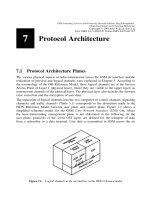
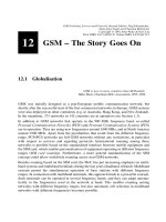
Along the way traveled by a mobile station, multipath fading can cause signi®cant varia-
tions of the received signal level (Figure 2.2). Periodically occurring signal breaks at a
distance of about half a wavelength are typically 30±40 dB. The smaller the transmission
bandwidth of the mobile radio system, the stronger the signal breaks ± at a bandwidth of
about 200 kHz per channel this effect is still very visible [8].
Furthermore, the fading dips become ¯atter as one of the multipath components becomes
stronger and more pronounced. Such a dominant signal component arises, for example, in
the case of a direct line of sight between mobile and base station, but it can also occur
under other conditions. If such a dominant signal component exists, we talk of a Rice
channel and Ricean fading, respectively. (S. O. Rice was an American scientist and
mathematician.) Otherwise, if all multipath components suffer from approximately
equal propagation conditions, we talk of Rayleigh fading. (J. W. Strutt, 3rd Baron
Rayleigh, was a British physicist, Nobel prize winner.)
During certain time periods or time slots, the transmission can be heavily impacted
because of fading or can be entirely impossible, whereas other time slots may be undis-
turbed. The results of this effect within the user data are alternating phases, which show
either a high or low bit error rate, which is leading to error bursts. The channel thus has
2 The Mobile Radio Channel and the Cellular Principle
10
memory in contrast to the statistically independent bit errors in memoryless symmetric
binary channels.
The signal level observed at a speci®c location is also determined by the phase shift of the
multipath signal components. This phase shift depends on the wavelength of the signal,
and thus the signal level at a ®xed location is also dependent on the transmission
frequency. Therefore the fading phenomena in radio communication are also frequency
speci®c. If the bandwidth of the mobile radio channel is small (narrowband signal), then
the whole frequency band of this channel is subject to the same propagation conditions,
and the mobile radio channel is considered frequency-nonselective. Depending on location
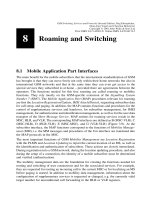
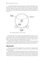
(Figure 2.2) and the spectral range (Figure 2.3), the received signal level of the channel,
however, can vary considerably. On the other hand, if the bandwidth of a channel is large
(broadband signal), the individual frequencies suffer from different degrees of fading
(Figure 2.3) and this is called a frequency-selective channel [15,54]. Signal breaks because
of frequency-selective fading along a signal path are much less frequent for a broadband
signal than for a narrowband signal, because the fading holes only shift within the band and
the received total signal energy remains relatively constant [8].
Besides frequency-selective fading, the different propagation times of the individual multi-
path components also cause time dispersion on their propagation paths. Therefore, signal
distortions can occur due to interference of one symbol with its neighboring symbols
(``intersymbol interference''). These distortions depend ®rst on the spread experienced
by a pulse on the mobile channel, and second on the duration of the symbol or of the
interval between symbols. Typical multipath channel delays have a range from half a
microsecond in urban areas to about 16±20 ms in mountainous terrain, i.e. a transmitted
pulse generates several echoes which reach the receiver with delays of up to 20 ms. In
digital mobile radio systems with typical symbol durations of a few microseconds, this can
lead to smearing of individual pulses over several symbol durations.
In contrast to wireline transmission, the mobile radio channel is a very bad transmission
medium of highly variable quality. This can go so far that the channel cuts out for short
periods (deep fading holes) or that single sections in the data stream are so much interfered
2.1 Characteristics of the Mobile Radio Channel
11
Figure 2.2: Typical signal in a channel with Rayleigh fading
with (bit error rate typically 10
22
or 10
21
), that unprotected transmission without further
protection or correction measures is hardly possible. Therefore, mobile information trans-
port requires additional, often very extensive measures, which compensate for the effects
of multipath propagation. First, an equalizer is necessary, which attempts to eliminate the
signal distortions caused by intersymbol interference. The operational principle of such an
equalizer for mobile radio is based on the estimation of the channel pulse response to
periodically transmitted, well-known bit patterns, known as the training sequences [4,64].
This allows the determination of the time dispersion of the channel and its compensation.
The performance of the equalizer has a signi®cant effect on the quality of the digital
transmission. On the other hand, for ef®cient transmission in digital mobile radio, channel
coding measures are indispensable, such as forward error correction with error-correcting
codes, which allows reduction of the effective bit error rate to a tolerable value (about 10
25
to 10
26
). Further important measures are control of the transmitter power and algorithms
for the compensation of signal interruptions in fading, which may be of such a short
duration that a disconnection of the call would not be appropriate.
2.2 Separation of Directions and Duplex Transmission
The most frequent form of communication is the bidirectional communication which
allows simultaneous transmitting and receiving. A system capable of doing this is called
full-duplex. One can also achieve full-duplex capability, if sending and receiving do not
occur simultaneously but switching between both phases is done so fast that it is not
noticed by the user, i.e. both directions can be used quasi-simultaneously. Modern digital
mobile radio systems are always full-duplex capable.
Essentially, two basic duplex procedures are employed: Frequency Division Duplex
(FDD) using different frequency bands in each direction, and Time Division Duplex
(TDD) which periodically switches the direction of transmission.
2 The Mobile Radio Channel and the Cellular Principle
12
Figure 2.3: Frequency selectivity of a mobile radio channel
2.2.1 Frequency Division Duplex (FDD)
The frequency duplex procedure has been used already in analog mobile radio systems and
is also used in digital systems. For the communication between mobile and base station,
the available frequency band is split into two partial bands, to enable simultaneous sending
and receiving. One partial band is assigned as uplink (from mobile to base station) and the
other partial band is assigned as downlink (from base to mobile station):
² Uplink: transmission band of mobile station receiving band of base station
² Downlink: receiving band of mobile station transmission band of base station
To achieve good separation between both directions, the partial bands must be a suf®cient
frequency distance apart, i.e. the frequency pairs of a connection assigned to uplink and
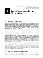
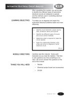
downlink must have this distance band between them. Usually, the same antenna is used
for sending and receiving. A duplexing unit is then used for the directional separation,
consisting essentially of two narrowband ®lters with steep ¯anks (Figure 2.4). These ®lters,
however, cannot be integrated, so pure frequency duplexing is not appropriate for systems
with small compact equipment [15].
2.2.2 Time Division Duplex (TDD)
Time duplexing is therefore a good alternative, especially in digital systems with time
division multiple access. Transmitter and receiver operate in this case only quasi-simulta-
neously at different points in time; i.e. the directional separation is achieved by switching
in time between transmission and reception, and thus no duplexing unit is required.
Switching occurs frequently enough that the communication appears to be over a quasi-
simultaneous full-duplex connection. However, out of the periodic interval T available for
the transmission of a time slot only a small part can be used, so that a time duplex system
requires more than twice the bit rate of a frequency duplex system.
2.2 Separation of Directions and Duplex Transmission
13
Figure 2.4: Frequency and time duplex (schematic)
2.3Multiple Access Procedures
The radio channel is a communication medium shared by many subscribers in one cell.
Mobile stations compete with one another for the frequency resource to transmit their
information streams. Without any other measures to control simultaneous access of several
users, collisions can occur (multiple access problem). Since collisions are very undesirable
for a connection-oriented communication like mobile telephony, the individual subscri-
bers/mobile stations must be assigned dedicated channels on demand. In order to divide the
available physical resources of a mobile system, i.e. the frequency bands, into voice
channels, special multiple access procedures are used which are presented in the following
(Figure 2.5).
2.3.1 Frequency Division Multiple Access (FDMA)
Frequency Division Multiple Access (FDMA) is one of the most common multiple access
procedures. The frequency band is divided into channels of equal bandwidth such that each
conversation is carried on a different frequency (Figure 2.6). Best suited to analog mobile
radio, FDMA systems include the C-Netz in Germany, TACS in the UK, and AMPS in the
USA. In the C-Netz, two frequency bands of 4.44 MHz each are subdivided into 222
individual communication channels at 20 kHz bandwidth. The effort in the base station to
realize a frequency division multiple access system is very high. Even though the required
hardware components are relatively simple, each channel needs its own transceiving unit.
Furthermore, the tolerance requirements for the high-frequency networks and the linearity
of the ampli®ers in the transmitter stages of the base station are quite high, since a large
number of channels need to be ampli®ed and transmitted together [15,54]. One also needs
a duplexing unit with ®lters for the transmitter and receiver units to enable full-duplex
operation, which makes it nearly impossible to build small, compact mobile stations, since
the required narrowband ®lters can hardly be realized with integrated circuits.
2 The Mobile Radio Channel and the Cellular Principle
14
Figure 2.5: Multiple access procedures
2.3.2 Time Division Multiple Access (TDMA)
Time Division Multiple Access (TDMA) is a more expensive technique, for it needs a
highly accurate synchronization between transmitter and receiver. The TDMA technique is
used in digital mobile radio systems. The individual mobile stations are cyclically assigned
a frequency for exclusive use only for the duration of a time slot. Furthermore, in most
cases the whole system bandwidth for a time slot is not assigned to one station, but the
system frequency range is subdivided into subbands, and TDMA is used for multiple
access to each subband. The subbands are known as carrier frequencies, and the mobile
systems using this technique are designated as multicarrier systems (not to be confused
with multicarrier modulation). The pan-European digital system GSM employs such a
combination of FDMA and TDMA; it is a multicarrier TDMA system. A frequency range
of 25 MHz holds 124 single channels (carrier frequencies) of 200 kHz bandwidth each,
with each of these frequency channels containing again 8 TDMA conversation channels.
Thus the sequence of time slots assigned to a mobile station represents the physical
channels of a TDMA system. In each time slot, the mobile station transmits a data
burst. The period assigned to a time slot for a mobile station thus also determines the
number of TDMA channels on a carrier frequency. The time slots of one period are
combined into a so-called TDMA frame. Figure 2.7 shows ®ve channels in a TDMA
system with a period of four time slots and three carrier frequencies.
The TDMA signal transmitted on a carrier frequency in general requires more bandwidth
than an FDMA signal, since because of multiple time use, the gross data rate has to be
correspondingly higher. For example, GSM systems employ a gross data rate (modulation
data rate) of 271 kbit/ s on a subband of 200 kHz, which amounts to 33.9 kbit/ s for each of
the eight time slots.
Especially narrowband systems suffer from time- and frequency-selective fading (Figures
2.2 and 2.3) as already mentioned. In addition, there are also frequency-selective co-
channel interferences, which can contribute to the deterioration of the transmission quality.
In a TDMA system, this leads to the phenomenon that the channel can be very good during
one time slot, and very bad during the next time slot when some bursts are strongly
interfered with. On the other hand, a TDMA system offers very good opportunities to
2.3 Multiple Access Procedures
15
Figure 2.6: Channels of an FDMA system (schematic)
attack and drastically reduce such frequency-selective interference by introducing a
frequency hopping technique. With this technique, each burst of a TDMA channel is
transmitted on a different frequency (Figure 2.8).
In this technique, selective interference on one frequency at worst hits only every ith time
slot, if there are i frequencies available for hopping. Thus the signal transmitted by a
frequency hopping technique uses frequency diversity. Of course, the hopping sequences
2 The Mobile Radio Channel and the Cellular Principle
16
Figure 2.7: TDMA channels on multiple carrier frequencies
Figure 2.8: TDMA with use of frequency hopping technique