Tài liệu Điện thoại di động mạng lưới Radio P10 pptx
Bạn đang xem bản rút gọn của tài liệu. Xem và tải ngay bản đầy đủ của tài liệu tại đây (508.91 KB, 8 trang )
10
Wireless Local Loop Systems
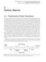
Wireline communications networks are expensive and time-consuming to con-
figure. Growing demand for telecommunications services and the imminent
liberalization of the telecommunications market in Europe have greatly in-
creased the interest in radio-based communication (Wireless Local Loops,
WLL), also referred to as Radio in the Local Loop (RLL), see [3].
Future competitors of telecommunications monopoly service providers,
such as power suppliers who already have their own wide-area networks, will
usually lack access networks to the end users. Message transfer over existing
power supply lines is currently being attempted using CDMA transmission,
and allows rates of several Mbit/s. The CEN 50 065 standard, which enables
the use of carrier frequencies of up to 140 kHz, is available for this purpose.
In 1997 Northern Telecom conducted its first field tests in this area in Great
Britain. If successful, the power supply network could be used in the future
as a user access network for voice and data services, playing a major role in
promoting competition and price reductions in telecommunications services.
Meeting the following requirements, wireless technology is very effective at
bridging the “last mile” of the path between the fixed network access of private
network operators (Point of Presence, POP) and the user:
• Fast and economic network configuration
• Economic network operations
• Flexible and expandable network structure
• Possible added-value through (restricted) mobility
For the user, a connection over a WLL system replaces the wireline
fixed network connection and should guarantee the same quality of ser-
vice characteristics—bit-error ratio, delay time and blocking probability—as
the public analogue telephone network (Public Switched Telephone Network,
PSTN) or even the Integrated Services Digital Network, ISDN.
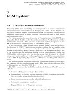
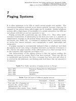
Figure 10.1 shows the different levels of mobility for a WLL user. In ad-
dition to connections without mobility in which the customer uses a normal
telephone connected through a cable to an antenna in the wall of the house,
systems with restricted mobility also exist, allowing a user to roam in a re-
stricted area, e.g., in a radio cell defined by an internal base station. Systems
in which users enjoy the same kind of mobility as in cellular mobile radio
Mobile Radio Networks: Networking and Protocols. Bernhard H. Walke
Copyright © 1999 John Wiley & Sons Ltd
ISBNs: 0-471-97595-8 (Hardback); 0-470-84193-1 (Electronic)
584 10 Wireless Local Loop Systems
✂✁☎✄☎✆
✝✟✞✠✞☛✡✌☞ ✍✏✎✠✑✓✒✠✍✠✔☛✑✠✕✠☞ ✖ ☞ ✍✘✗
✝✟✞✠✞☛✡✌☞ ✍✏✎✚✙✜✛✠✢✣✍✏✙✜☞ ✤✣✍✘✛✠✥✚✔☛✑✠✕✠☞ ✖ ☞ ✍✏✗
Figure 10.1: WLL without and with restricted mobility
✂✁☎✄✆ ✂✝✟✞✡✠☛✁✂☞✌✝✍☞✌✎ ✏✍✑
✒✔✓✟✕✗✖✙✘✛✚✢✜✤✣
✥
✜✤✣✦✚★✧✪✩✟✫✤✬
✭✯✮☛✰☎✄✱✭✤✠✍☞✌✲✯✏✟✳✵✴✶✮☛✝✍✑✟✝✟✷✍✠✟✸☛✠✍✑✟☞✟✰✂✷✍✠✟✑✟☞
✹ ✺✼✻✾✽
✿ ❀❂❁❄❃❅✄✆❆✶❇✟✠✍✳✵✝✟☞✌✎ ✏✍✑✟✝✟❈✡✝✟✑✟❉❊✮☛✝✍✎ ✑✟☞✪✠✟✑✟✝✍✑✟❋●✠❍✿ ✑✟☞✌✠✍✳✵■✌✝✟❋✡✠
✿ ❀❂❁❄❏❅✄✟❑▲✝✍❉✟✎ ✏❊▼◆✠✟✳✵✸❊✎ ✑✟✝✍☞✌✎ ✏✍✑☛☞✌✏❊▼◆✠✟✳✵✸❊✎ ✑✟✝✍❈❖✿ ✑✍☞✌✠✟✳✵■✌✝✍❋●✠
✿ ❀❂❁❄❅✄✆✰✂✎ ✳◗✿ ✑✟☞✪✠✟✳✵■✌✝✟❋✡✠
✿ ❀❘❁❄❙❅✄✱❚✤✏✍✑✟☞✌✳✵✏✟❈ ❈ ✠✍✳◆☞✌✏☛ ✂✝✍✞●✠❊✁✂☞✌✝✟☞✌✎ ✏✍✑❯✿ ✑✍☞✌✠✟✳✵■✌✝✍❋●✠
✿ ❀❘❁◆❱✟✄✱❲✟✏✟❋✡✝✟❈❖❳✗❨✡❋●❩✍✝✟✑✟✷✍✠☛☞✌✏❊❚✯✏✟✑✟☞✌✳✵✏✍❈ ❈ ✠✍✳◗✿ ✑✟☞✌✠✍✳✵■✌✝✟❋✡✠
✿ ❀❘❁❄❬❅✄✱✭✤✮❊✰❭☞✌✏❊ ✂✝✟✞●✠❊✁✂☞✌✝✟☞✌✎ ✏✟✑❍✿ ✑✟☞✌✠✍✳✵■✌✝✟❋✡✠
✥
✜✤✣✦✚❪✧❫✩✟✫❅✖❴✧ ✘✤✩
❵❅❛
❜❞❝❢❡
✒☛✘✤✩❣✖❴✣❤✘✤✬❫✬ ✜✤✣
✐
❡✢❥
✹ ✺❴✻✯❦
✹ ✺❴✻✾❧
✹ ✺✼✻✾♠
♥♣♦ q
✫❅r✤✧ ✘
❲❅❳✂✄✆❲✍✏✟❋✡✝✟❈❖❳✗❨✡❋●❩✍✝✟✑✟✷✍✠
st❵❅❵✉♦✶✈
✕✗✖✙✜✤✚
✹ ✺❴✻✾✇
✹ ✺❴✻▲①
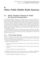
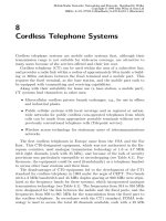
Figure 10.2: ETSI reference model for WLL systems
networks (e.g. GSM) are called Personal Communications Systems (PCS);
see Section 3.15.
Because of the great interest in WLL technology for the above reasons,
the ETSI working party Radio Equipment and Systems 3 (ETSI RES 3),
founded in January 1993, published a report [1] in November 1994 addressing
the marketing aspects, different WLL technologies as well as scenarios and
characteristics that are of interest from the standpoint of the dimensioning of
WLL systems, such as radio range and capacity aspects. The reference model
presented in Figure 10.2 originates from this report.
The reference model shows the interfaces of a WLL system and its elements.
In addition to antennas, the base station (BS) has facilities for measuring
and controlling radio connections with the radio termination of the customer
terminal. The controller connects the base station to the local exchange (LE)
and controls the base station.
10.1 Technologies for WLL Systems
The following technologies are suitable for WLL systems [2]:
• Analogue cellular mobile radio
10.1 Technologies for WLL Systems 585
• GSM/DCS1800 derivations
• CDMA systems based on US-TIA standard IS-95
• Digital cordless radio networks:
– DECT
– Personal Handyphone System, PHS (Japan)
– US Personal Access Communication System (PACS)
• Digital point-to-multipoint (PMP) radio relay systems
Directional antennas with, e.g., 5–12 dB gain are normally provided for
stationary residential lines to enable a low bit-error ratio on the radio channel
to be achieved even when base stations have a large coverage radius (typically
2–5 km). However, discussions are also taking place about systems in which
the stationary customer line can get by with an indoor antenna, which then
has to be small and unobtrusive. The base station then of course has to
operate with smaller supply radii.
The suitability of the systems mentioned above depends heavily on the
types of user—in other words on the services that are to be offered by the
WLL system. A differentiation is made between the following types of user:
• Residential users who require an analogue (PSTN) connection or an
ISDN basic rate interface (BRI).
• Small-business customers who operate a small branch exchange for
which they require a number of ISDN BRIs (each with n·144 kbit/s) but
for whom an ISDN primary rate interface (PRI) would be impractical
and too expensive.
• Large-business customers who operate large branch exchanges and re-
quire a gateway to data networks such as X.21 and X.25 and frame
relay along with normal telephone applications. Their connection ca-
pacity needs are on the order of one or more ISDN PRIs (n · 2048 kbit/s,
n = 1, 2, . . .).
10.1.1 Cellular Mobile Radio Networks
The Ericsson RAS 1000 System, which is based on the NMT standard (Nordic
Mobile Telephony), was used by Deutsche Telekom AG (DTAG) in 1993 to
connect around 13 000 customers in Potsdam, Germany. However, analogue
cellular systems are no longer competitive compared with the other systems
presented here because of the high cost per connection and the disadvantages
compared with digital networks.
Experiments have also been made with digital mobile radio networks. Stud-
ies have been conducted with systems such as GSM900/1800 to determine the
586 10 Wireless Local Loop Systems
✁✂ ✂✄
☎ ☎✆
✝✞✟ ✟
✠ ✠
✡☛
☞ ☞✌✍✎ ✏✑
✒ ✒
✒ ✒✓
✓
✔✕ ✕✖
✗
✗
✘ ✙✚
✛
✜ ✢✣
✤ ✥ ✥
✥ ✥✦
✦
✧★ ★✩
✪
✫
✫✬
✬
✭
✭✮
✮
✯ ✯
✯ ✯✰
✰
✱
✱✲
✲
✳✴ ✵✶
✷✹✸
✺ ✻ ✼
✽
✺✿✾❀
❁✹❂
✾
✻ ❃
❂
❄❆❅❈❇❊❉❋❇❍●■❅❏●▲❑ ▼❖◆
❆▼◗❑ ◆❘●❚❙❯●■▼❈❙❲❱❘▼◗❑ ◆❘●◗❳❨❅❈❩❖❑ ▼❬❳❭❉◗❪ ❅❏❫
❆▼◗❑ ◆❘●❚❙❯●■▼❈❙❲❴❛❵❈❪ ●❜❑ ❱❝▼◗❑ ◆❘●◗❳❨❅❈❩❖❑ ▼❞❳❭❉❖❪ ❅❈❫
❡❢❑ ❣❊❉❈❩❞❤❥✐❆❦♠❧♥❦❥▼◗◆❏◆❝❉❏♦❍●❜❑ ▼◗◆❛❄❆▼❈❣
♣
❑ ●▲qr❩❖❑ ❳❭❉❏♦❍●❜❑ ▼◗◆❘❅◗❪s❅◗◆❘●■❉◗◆❏◆❝❅
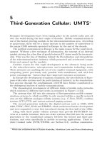
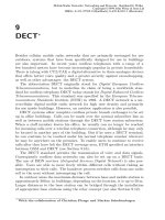
Figure 10.3: Customer coverage by over the roofs supply
✁
✁
✂
✂✄
✄
☎✆
✝
✝✞
✞
✟ ✟
✟ ✟✠
✠
✡ ✡☛
☞ ☞
☞ ☞✌
✌
✍
✍✎
✎
✏ ✏
✏ ✏✑
✑
✒✓✔ ✔✕
✖ ✖✗
✘✚✙
✛ ✜ ✢
✣
✛✥✤✦
✧✚★
✤
✜ ✩
★
✪✬✫ ✭✯✮✱✰✳✲✵✴✷✶✹✸✺✶✵✻✽✼✾✼✿✮✾❀❂❁❃✫ ✻✽✼❅❄✷✻✱✭
❄✷❆✱❇✯✮❈❇✯❁❉❆✱❁❃✫ ✻✽✼
✲✵✴✷✶✹✸✬❊●❋❍✮❍■ ❆✱❏✯❇
❑✷✻✽✫ ✼▲❁▼❊◆❁❉✻✱❊❖▲✻✽✫ ✼▲❁✽◗❘❆✱✰❍✫ ✻❙◗❚✮✽■ ❆✾❏
❑✷✻✽✫ ✼▲❁▼❊◆❁❉✻✱❊❯❅❱✱■ ❁❃✫ ❖✿✻✽✫ ✼▲❁✽◗❘❆✱✰❍✫ ✻✳◗❚✮❍■ ❆✱❏
Figure 10.4: Customer coverage by below the roofs supply
feasibility of the possibility shown in the lower part of Figure 10.1. This would
allow customers to communicate cost-effectively indoors using their home base
stations and to use the same terminal to access the corresponding cellular net-
work. However, mobile radio networks only offer narrowband channels and
therefore cannot achieve the quality of service of a PSTN or ISDN/BRI access
for wireline users. Nevertheless, all users who just want to place a call have
access to the wireless connection to the mobile radio networks.
10.1.2 Digital Cordless Radio Networks
Some of the new network operators are pinning their hopes on WLL systems
based on the DECT standard or on CT2 or PHS. At around 300–400 US$,
the cost per connection is considerably less than with GSM-based solutions.
DECT is able to support coverage over the roofs as well as below the roofs (see
Figures 10.3 and 10.4). Over the roofs coverage would not be able to reach
ditches, but with low-gain receiving antennas could penetrate through house
walls. Below the roofs systems operate with base stations (Radio Fixed Parts,
10.2 Different WLL Scenarios 587
Table 10.1: Frequency bands for WLL systems in Europe
Frequency band [GHz]
Applications Channel grid [MHz]
24.549 . . . 26.061 PMP radio relay 3.5, 7, 14
17 Radio relay for Hiperlan/4
3.41 . . . 3.60 PMP radio relay 3.5
2.5 . . . 2.67 PMP radio relay
1.88 . . . 1.9 DECT-WLL 1.7
RFP) that are installed under the roof, thereby illuminating the ditches and
enabling full mobility of the PCS system both indoors and outdoors.
10.1.3 Digital PMP Systems
Point-to-multipoint radio relay systems offer attractive connection options
particularly for business customers, because they can provide the customer
with channels with high transmission rates. The frequencies for PMP-WLL
applications are listed in Table 10.1.
WLL systems based on PMP technology are offered by a large number of
suppliers, and represent an interesting connection option in urban and rural
areas because of their ability to bridge up to 20 km in borderline cases. Be-
cause the transmission capacity needs of stationary customers connected over
PMP systems vary, there exist PMP radio relay systems that can dynamically
change their (switched) channels in terms of capacity and allocate them to the
areas where they are most urgently needed (see Figure 10.5).
PMP systems are frequently also implemented as multihop systems, as
shown in Figure 10.6. Several radio links (Line-of-Sight Radio, LOS) belong-
ing to point-to-point or point-to-multipoint (PMP) systems are arranged se-
quentially in order to bridge the path between the fixed network access (Point
of Presence, POP) and the customer’s connection. Another interesting op-
tion offered by a number of manufacturers is a combination of PMP systems
with DECT systems connected to a PMP end terminal for the connection of
residential customers.
10.2 Different WLL Scenarios
The competitive scenarios examined here are based on standard scenarios from
ETSI RES-3 [1]. The following scenarios were defined:
1. An existing operator, new area to be developed.
2. Replacement of copper lines with WLL.
3. Reaching the capacity limits of an existing fixed network.