Tài liệu Điện thoại di động mạng lưới Radio P12 ppt
Bạn đang xem bản rút gọn của tài liệu. Xem và tải ngay bản đầy đủ của tài liệu tại đây (889.68 KB, 38 trang )
12
Wireless Broadband Systems and
Wireless ATM
∗
Broadband systems are generally those systems that provide a high transmis-
sion rate besides other features like integration of services. An exact definition
of this term can be found in ITU Rec. I.113, which characterizes broadband
services as having a higher transmission rate than a primary multiplex con-
nection in ISDN (2048 kbit/s).
A brief overview of the current state of development of wireless broadband
systems, particularly in Europe, including the fundamentals of ATM in B-
ISDN, is given below. This is followed by important aspects of development
of wireless ATM for movable and mobile stations.
12.1 European Research in Broadband Systems
The importance of wireless broadband systems is evident from the number
of projects being carried out in this field, e.g., within the European research
programme ACTS (Advanced Communication Technologies and Services) [2]:
ACTS/MEDIAN Wireless LAN at 60 GHz transmission of ATM cells;
ACTS/Cobucco Multimedia terminal;
ACTS/FRANS High-bit-rate subscriber connections;
ACTS/MagicWAND Indoor wireless ATM system at 5 GHz;
ACTS/OnTheMove Mobile multimedia value-added services;
ACTS/SAMBA Cellular ATM broadband system at 40 GHz;
ACTS/CABSINET Cellular interactive multimedia communications system
for metropolitan areas (at 5, 17, 40 GHz);
ETSI/RES 10 HIPERLAN 1 (wireless LAN with 23 Mbit/s at 5 GHz; see
Section 13.2);
∗
With the collaboration of Andreas Hettich, Arndt Kadelka, Andreas Kr¨am-
ling, Dietmar Petras
Mobile Radio Networks: Networking and Protocols. Bernhard H. Walke
Copyright ©1999 John Wiley & Sons Ltd
ISBNs: 0-471-97595-8 (Hardback); 0-470-84193-1 (Electronic)
618 12 Wireless Broadband Systems and Wireless ATM
ETSI/BRAN Broadband wireless access networks that also support ATM;
ATM Forum TCP over ATM, MPEG over ATM, wireless ATM;
DAVIC/LMDS Digital And Video Council/Local Multipoint Distribution
System;
ATMmobil Key development project of the Federal German Minister of Re-
search and Technology: development of wireless ATM systems (at 5, 19,
40, 60 GHz).
A brief discussion of some of the projects follows.
Until 1995, the EU research programmes RACE (Research and Develop-
ment in Advanced Communications Technologies in Europe) I and RACE II
were devoted to the development and testing of prototypes of systems with
broadband radio transmission.
From 1992 to 1994 the RACE II programme promoted the development of
third-generation mobile radio systems, with the objective of integrating GSM,
DECT, paging, mobile satellite radio and trunked mobile radio systems along
with their different applications into an Universal Mobile Telecommunications
System (UMTS) with a multiplex data rate up to 2 Mbit/s at the radio in-
terface. This effort included the development of standardized terminals and
an expansion of services with high data rates.
Along with these systems, which were designed to provide a high degree
of mobility, the RACE II project MBS (Mobile Broadband System) under-
took the development and testing of a technology and system concept for a
wireless ATM system at 60 GHz that demonstrated the possibility of video
transmission with a 16 Mbit/s transmission rate (net) at a 50 km/h speed of
movement of the terminal [11, 32].
12.1.1 MBS
The RACE II/MBS project undertook studies of techniques for linking mobile
terminals to stationary broadband networks with data rates at the multiplex
radio interface of up to 155 Mbit/s. Narrowband services were also to be pro-
vided. The MBS system made a particularly important impact, and convinced
the professional world of the possibility of providing the services of broadband
ISDN to mobile users through wireless ATM transmission [6, 22, 29, 31, 33].
In addition to providing a link-up to the broadband ISDN, the MBS concept
also supports a cooperation with other systems such as UMTS. The type of
network and level of integration can vary all the way from a privately operated
MBS system with a low level of service integration and mobility up to a public
MBS system with a high level of integration, extensive mobility and coverage
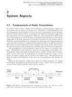
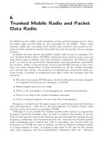
of a wide area [5]. Figure 12.1 shows MBS in relationship to other systems
with differing levels of mobility support for their terminals and transmission
rates. It can be seen that MBS combines the wide-ranging service spectrum of
broadband ISDN with the mobility of mobile radio networks whilst offering the
12.1 European Research in Broadband Systems 619
9.6 2 155
kbit / s Mbit / s
B-ISDN
MBS
UMTS
ISDN
GSM
20
Wireless LANs
DECT-
RLL
MBS-RLL
Medium
Fast
Movable
Fixed
Available bit rate
Terminal mobility
Figure 12.1: MBS and other data networks
services of wideband and narrowband systems such as UMTS, W-LAN, GSM,
DECT and their derivatives for Radio in the Local Loop (RLL) applications.
Owing to the flexibility of MBS and the availability of the services of B-
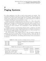
ISDN, a variety of different applications are possible. These are indicated
(with no claim to completeness) according to the data rates required and the
mobility of their users in Figure 12.2.
The author and his research group were responsible for designing the radio
and network protocols for MBS, which, although they were not implemented
in the demonstrator system, were developed as part of the project and were
incorporated into a number of successor projects in the ACTS programme,
where they were developed further (see Section 12.1.2). For example, the
MBS project as one of the first proposed an ATM-based radio interface for
mobile use and specified it as part of the system [29, 30, 36].
12.1.2 Wireless Broadband Communications in the ACTS
Programme
As the successor to RACE II, the ACTS research programme [3] of the Eu-
ropean Union was conducting field trials and demonstrations to monitor the
developed systems for real applications.
Along with the development of UMTS, promising attributes of MBS have
been developed further in the following ACTS projects.
12.1.2.1 MEDIAN
MEDIAN (Wireless Broadband CPN/LAN ( Customer Premises Network) for
Professional and Residential Multimedia Applications) develops transmission
620 12 Wireless Broadband Systems and Wireless ATM
2
8 34 155
Movable Slow mobile Fast mobile
City Guidance
Alarm Detection
Teleconsulting
CAD Interconnection
Special needs
(e.g., health)
Required Datarate, [Mbit/s]
User mobility
HDTV Contribution
Cordless HDTV
Studios
Pictorial data for
travel
Public transport
travel advice
Electronic Newspaper
Traffic Advice
Emergency Services
Audio/Visual Library
HD Video Phone
Surveillance
of Property
Freight Management
Interconnection of
Mobile LANs
Interactive
"Quasi-Real-Time"
Services
Access to
Banking Services
Figure 12.2: MBS applications and services
technology at 60 GHz for wireless networks at data rates of up to 155 Mbit/s
for multimedia, voice and video applications.
The goal is to develop a demonstration system for multimedia applications,
including research into modulation, channel coding, channel access methods
and cooperation with ATM fixed networks at high data rates. MEDIAN
provided B-ISDN access to mobile users through transparent transmission of
the ATM cells of B-ISDN over the radio interface.
12.1.2.2 Magic WAND
WAND (Wireless ATM Network Demonstrator) extended the use of ATM
technology to mobile users, and examined realistic user environments. The
field of application covered Internet services over ATM in indoor areas with a
20 Mbit/s transmission rate at 5 GHz. The project realized an indoor wireless
ATM demonstration network.
The emphasis was on modelling the radio channel and developing channel
access protocols, as well as new control and signalling functions to be sub-
mitted to ETSI for possible adoption in a later standard for wireless ATM
systems.
12.1 European Research in Broadband Systems 621
12.1.2.3 SAMBA
SAMBA (System for Advanced Multimedia Broadband Applications) aimed to
expand the ATM fixed network using a cellular radio access network to pro-
vide mobile users with access to broadband multimedia applications. Mobile
ATM terminals have been shown to be able to access services comparable
to those used by terminals in the ATM fixed network. Therefore, besides the
development of the system elements, the main priorities of SAMBA were inte-
gration of ATM fixed network and mobile support. A demonstration system at
40 GHz has been created and demonstrated at the EXPO’98 in Lisbon which
provided transparent ATM links with transmission rates of up to 34 Mbit/s
for all ATM categories of service.
In contrast to other ACTS broadband projects, the time-critical ATM ser-
vices CBR (Constant Bit Rat) and VBR (Variable Bit Rate) were also sup-
ported and appropriate provisions made for radio protocols so that the radio
channel offered a quality of service comparable to a fibre-optic transmission
path (within the framework of ATM quality of service requirements).
The SAMBA project also developed a technology, not yet provided by the
ATM Forum, for call handover between different ATM fixed network access
points. The author and his research group were responsible for the imple-
mentation of the protocols of the radio interface and of the ATM network
protocols, using their experience from MBS (see Section 12.1.1) [25, 27].
12.1.2.4 AWACS
The AWACS (ATM Wireless Access Communication System) project further
developed a system based on the NTT/AWA system and developed a demon-
strator to support terminals with limited mobility and provide public access
to the ATM fixed network. The system operates in the 19 GHz range and
provides users with user data rates of up to 34 Mbit/s.
In addition to developing the demonstrator, AWACS carried out extensive
research in the areas of channel and source coding, intelligent antennas, op-
timization of LLC protocols, 40 GHz transmission technology and mobility
management.
12.1.2.5 AMUSE
AMUSE (Advanced Multimedia Services for Residential Users) specified and
developed a demonstrator for advanced multimedia services to link residential
customers to an ATM infrastructure. The services were offered under real
conditions through the use of different technologies such as HFC (Hybrid Fibre
Coax), ADSL (Asymmetrical Digital Subscriber Line), FTTC/FTTB (Fibre
to the Curb/Building) and WLL (Wireless Local Loop).
A possibility has been explored for setting up end-to-end links to different
access networks. Moreover, the individual local field tests have been linked
over the European ATM network.
622 12 Wireless Broadband Systems and Wireless ATM
The project was set up in two phases: services such as Video on Demand
(VoD), News on Demand (NoD) and high-speed Internet access were devel-
oped in the first phase; other services were offered in the second phase.
12.1.3 ATMmobil
This 1996–2000 programme of the German Ministry of Research and Technol-
ogy is involved in the development of concepts and the corresponding demon-
strators for four forms of wireless ATM systems.
The concept ATM-RLL (Radio in the Local Loop) promotes using ATM
point-to-multipoint line-of-sight radio at 26/40 GHz to bridge the last few
miles in a local loop area.
The second concept (W-ATM LAN) is examining the wireless connection
of mobile computers to support multimedia applications at 5 and 19 GHz [8].
The third concept (cellular W-ATM) links mobile terminals with an ATM
radio interface over a cellular network at 5 GHz to an ATM broadband network
access point [4].
The fourth concept (Integrated Broadband Mobile System, IBMS) involves
the development of wireless transmission technology for indoors and outdoors.
Along with infrared as the medium for indoor purposes, millimetre waves at
5, 17, 40 and 60 GHz are being used. Adaptive antennas, single-carrier trans-
mission technology, radio interface, radio resources and mobility management
are the focus of research [12].
Similarly to UMTS for mobile radio systems with multiplex transmission
rates of up to 2 Mbit/s at the radio interface, the integrated individual con-
cepts mentioned above are being pursued within the framework of ATMmobil.
The author propoded and headed the ATMmobil project, and members of his
research group participated in the implementation work of the first, second
and third concept mentioned above and were also involved in the ETSI-BRAN
standardization (see Section 12.1.5).
12.1.4 The Role of the ATM Forum in the Standardization
of Wireless ATM Systems
Although the ATM Forum is not an official standards body, it is playing an
important role in the quasi-standardization of certain forms of the ATM fixed
network through its association with industry and its products. In June 1996
the ATM Forum became involved in WLAN standardization. The WLAN
group originally wanted to focus its attention on mobility support by ATM
fixed networks, a project that was supposed to run until the first quarter
of 1999 [28]. There are now indications that the radio interface will also
be addressed. Based on the experience of 1998, the anticipated market for
wireless ATM systems is already so large that the standardization of the radio
interface for worldwide use will not be left up to Europe (ETSI) only.
12.2 Services in Broadband ISDN 623
✂✁☎✄✝✆✝✞✂✟✡✠☞☛ ✂✁☎✄✝✆✝✞✂✟✡✠☞☛ ✂✁☎✄✝✆✝✞✂✟✡✠☞☛ ✂✁☎✄✝✆✝✞✂✟✡✠☞☛
✌✎✍✑✏✡✒✔✓ ✌✎✍✑✏✡✒✖✕ ✌✎✍✑✏✡✒✖✗ ✌✎✍✑✏✡✒✖✘
✙✝✚✑✛✢✜✤✣✖✥✦✚✑✧✩★
✪✢✫ ✬✤✭✯✮ ✭✱✰✩✰✳✲✵✴✷✶
✸✱✹✻✺✽✼✖✾
✫ ✿☎❀❁✰
✙✝✚✑✛✢✜✤✣✖✥✦✚✑✧✩★
✸✱✹✻✺✽✼✖✾
✫ ✿☎❀❁✰
✪❂✫ ✬✤✭✑✮ ✭✻✰✩✰❃✴✝❄
✼
✼
✴✝❅
✪✢✫ ✬✤✭✯✮ ✭✱✰✩✰✳✲✵✴✷✶ ✪❂✫ ✬✤✭✑✮ ✭✻✰✩✰❃✴✝❄
✼
✼
✴✝❅
✪✢✫ ✬✤✭✯✮ ✭✱✰✩✰✳✲✻✲
✜❆✲❈❇✻❉✩❊✯✮✩✲✵❇✱❇✯❋❈★
✼
✴✝❅
✪❂✫ ✬●✭✯✮ ✭✻✰✩✰✳❍ ❅■✶
✜❏❍☎❑❈✿❁✭✯✬✤❉✩❇✑❑✻❑✵✭✱❉✩✿☎★
✼
✴✝❅
✪✢✫ ✬✤✭✯✮ ✭✱✰✩✰✳✲✻✲ ✪❂✫ ✬●✭✯✮ ✭✻✰✩✰✳❍ ❅■✶
✙✝✚✑✛✢✜❆▲❈▼✖✥✳✚◆✧✩★
▲❈✣
✹✱✺✽✼✖✾
✫ ✿❁❀❁✰
✙✝✚✑✛✢✜✤✣✖✥✦✚✑✧✩★
✸✱✹✻✺✽✼✖✾
✫ ✿☎❀❁✰
✴❖❄
✼◗
❇✯✬❏✫ ✭✯❑❈✿☎✭✱❘✔✚✂❍☎✙✝❙✝❚✂✲✵✴✷✶◆✰
Mobile Wireless Networks Stationary Wireless Networks
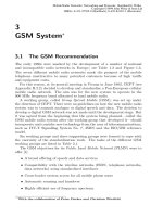
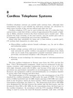
Figure 12.3: The four different types of HIPERLAN
12.1.5 The ETSI Contribution to W-ATM Standardization
The standardization group ETSI RES 10 (Radio Equipment and Systems,
RES), now ETSI BRAN (Broadband Radio Access Networks), is currently de-
veloping a family of standards referred to as HIPERLAN (High-Performance
Radio Local Area Network) for wireless broadband communication at 5 and
17 GHz. There are four different types of HIPERLAN:
HIPERLAN Type 1 is a standard for wireless communication between com-
puter systems at 5 GHz in close proximity to one another (see Chap-
ter 13).
HIPERLAN Type 2 refers to a wireless access system at 5 GHz to ATM fixed
networks with a multiplex bit rate of 25 Mbit/s for W-ATM LANs.
HIPERLAN Type 3 is also referred to as HIPERACCESS. It is an application
in HIPERLAN Type 2 technology at 5 GHz for outdoor distances of up
to 1 km (W-ATM RLL).
HIPERLAN Type 4 at 17 GHz is also referred to as HIPERLINK. It will
offer rates of up to 155 Mbit/s for short distances for the connection of
W-ATM systems.
The ETSI BRAN group is standardizing the radio interface [10] (see Fig-
ure 12.3). The status as of September 1998 can be found in [17].
Table 12.1 presents a comparison of the key features of all four systems.
12.2 Services in Broadband ISDN
Multiplex data rates of up to 155 Mbit/s on the wireless user connection are
necessary for the integration of wireless broadband applications in B-ISDN.
These kinds of applications require services for continuous interactive data
624 12 Wireless Broadband Systems and Wireless ATM
Table 12.1: Parameters of the ETSI BRAN HIPERLANs
HIPERLAN Type 1 Type 2 Type 3 Type 4
Wireless LAN ATM Local loop Point-
to-point
Carrier freq. 5 5 5 17
[GHz]
Network top. Decentral Central PTP PTP
Antennas Omni Omni Lobe Directional
Cell type Pico Pico Cigar Like Radio relay
Area of applic. Ind./Outd. Ind./Outd. Outd. Ind./Outd.
Operator Private Private/Public Private/Public Private
Mobility Port./Move. Port./Move. Stationary Stationary
Backbone LAN B-ISDN, ATM ATM network B-ISDN
Data rate 20 24 48 155
[MBit/s]
Comm. range 50–100 50–100 5000 50–500
[m]
Product [Year] 1998 2000 After 2000 After 2000
as well as for bursty-type interactive data. Along with voice transmission,
applications with continuous bit streams include video conferencing in which
real-time requirements must also be strictly maintained. Interactive services
are characterized by a wide fluctuation in the requirements for bit rates. Thus
a short information request to a database can result in a very long response
(counted in bit time) requiring a high transmission rate. A distinction is made
between the following:
• Interactive services
– Telefony – Video telephony – Broadband video conferencing
• Inquiry services
– Access to databases
– Radio, TV, HDTV,
Video-on-Demand
– Electronic newspaper
– Videopost
• Data communications
– LAN links
– File transfer
– CAM links
– High-resolution
video transmission
Synchronous transmission methods (Synchronous Time-Division Multiplex-
ing, STDM) have difficulty coping with the varying requirements of broadband
services. Although an oversizing of the transmission capacity of synchronous
channels reduces waiting times, it results in a poor utilization of capacity in
the transmission medium. ATM technology (Asynchronous Transfer Mode) is
better suited to dealing with the demands of broadband services.
12.2 Services in Broadband ISDN 625
Σ
Connection A
Connection B
Connection C
Connection A
Connection B
Connection C
Empty Cells
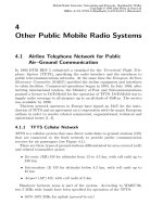
Cell stream behind multiplexer
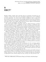
Figure 12.4: Statistical multiplexing of cells to a medium
12.2.1 ATM as a Transmission Technology in B-ISDN
Asynchronous Transfer Mode (ATM) is the connection-oriented packet-
switching method used in B-ISDN. ATM combines the advantages of connec-
tion and packet-oriented switching—specifically the statistical multiplexing of
data from different connections to one medium and the message switching of
packets in the network nodes between the communicating terminals. The data
streams to be transmitted are divided into short blocks of a fixed length, re-
ferred to as ATM cells. The cells of different connections are transmitted with
time interleaving over a physical channel. Depending on their data rates, the
connections are dynamically allocated varying amounts of transmission ca-
pacity, with some of them transmitting a large number of cells per time unit
and others only very few. The cells in each connection are transmitted in the
order of their arrival.
The ATM multiplexer adds empty cells to the multiplex data stream if
none of the connections requires transmission capacity and a synchronous
transmission method is being used (see Figure 12.4).
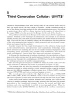
12.2.2 Structure of an ATM Cell
An ATM cell comprises 53 bytes, consisting of a 5-byte long header field and
a 48-byte long information field containing data of the higher ATM protocol-
stack layers and user data. The switching of the cells is connection-oriented.
All cells in a virtual connection take the same transmission path, which was
established when virtual channels were set up on different switching sections in
the network during call setup. The cells are controlled through the network on
the basis of the routing information stored in the cell header (see Figure 12.5).
VCI (Virtual Channel Identifier ), 2 bytes An identification of the virtual
channel differentiates between the different concurrent logical channels
and their cells. The virtual channel number is always only assigned to
one switching section.
VPI (Virtual Path Identifier), 8 or 12 bits A channel group is identified by
the parameter VPI. A differentiation can be made between a large num-
626 12 Wireless Broadband Systems and Wireless ATM
✂✁☎✄✝✆✞ ✠✟✞✡✞✟✞☛✌☞ ✍✎✁✑✏ ✒✔✓✕✄✝✒✞✡✔✖✗☛✌✒✞✏
✘✝✙
✄✝✆
✘
✟✞✚✞✛✜✟✞☛
✙
☛✢☛✌✒✞☛✑✄✝✒✞✡✔✖✣☛✌✒✞✏ ✤✝✤✝✥ ✆✞✤✝✟✔✖ ✓✦✒✞☛✌✧✩★✌✤✝✒✞✛✞✟✪✥ ✡✔✖✗✟✞☛ ✫✣✚✔✍☎✟
✬✂✭
✥ ✆
✬
☞ ☛ ✖✗✮✞✚✞✏
✭
✚✔✖✗✯✦✥ ✛✞✟✞✡✔✖✗☞ ✫✗☞ ✟✞☛
✄✝✰
✭
✆✪✄✝✟✞✏ ✏✩✰✞✒✔✱✩✱
✭
☛✌☞ ✒✜☛✢☞ ✖ ✲
✭✜✳
✆
✭
✚✔✲☎✏ ✒✞✚✞✛
✳
✲☎✴✞✟
✵
✤✝✥ ✆
✵
✱☎✟✞☛✌★✢✤✝✟✔✖ ✓✦✒✞☛✌✧✂✥ ✡✔✖✣✟✞☛ ✫✗✚✔✍✶✟
✬
✄✝✥ ✆
✬
☞ ☛ ✖✗✮✞✚✞✏✩✄✝✯✞✚✞✡✞✡✞✟✞✏✩✥ ✛✞✟✞✡✔✖✣☞ ✫✣☞ ✟✞☛
✷✹✸✂✺
✻
✺✽✼
✻
✷✾✼
✻
✷✾✼
✻
✷✾✼
✿❁❀❂✷
❃❅❄
✷
✷✹✸✂✺
✻
✺✽✼
❃✾❄
✷
✺❇❆
✻
✷✾✼
✻
✷✾✼
✻
✷✾✼
✻
✺✽✼
✺❇❆
✻
✺✽✼
❈✽❉
✼ ❊●❋■❍❏❍✹❍✾✼
❈✽❉
✼ ❊●❋■❍❏❑✹❍✾✼
▲
✲✩✖✗✟
▼
◆
❖
◗
Figure 12.5: Header of an ATM cell
ber of groups in the same direction, each containing several virtual chan-
nels. The cells of channels in the same group can be processed especially
quickly by the switch-fabric of an ATM switch and then forwarded;
cross-connects are used for this purpose.
PT (Payload Type), 3 bits This parameter describes the type of information
field and provides a differentiation between user and signalling infor-
mation. The signalling information is required, for example, to update
the routing tables managed in the switching centres. The switching
centre carries out updates by evaluating the header field as well as the
information field of the ATM cell. User data being transmitted in the
information field of an ATM cell is not taken into account in the switch-
ing.
HEC (Header Error Control), 1 byte Because the header of an ATM cell con-
tains data that is vital to the transport of the cells, it is protected by a
checksum. This permits the detection of transmission errors.
CLP (Cell Loss Priority), 1 bit This parameter identifies cells with a lower
priority, which are discarded in the ATM switching centre when there is
an overflow in the queue. The bit is also used by multiplex and switching
nodes for flow control and traffic shaping.
12.2.3 ATM Switching Technology
As with other packet-switched methods, ATM cells are switched on the ba-
sis of the routing information contained in the cell header. The complete
originating and target addresses are sent only during connection setup, so
that the routing information can be kept as short as possible, thus increasing
throughput. Identification of the logical channels is assigned for the differ-
ent sections of a connection (VCI, VPI). During connection setup, the ATM
switching centres enter relationships between input and output identification
(line + logical channel identification) into their routing tables using incoming
control information.
12.2 Services in Broadband ISDN 627
VCI 1
VCI 2
VPI 1
VPI 2
VPI 3
VPI 4
VPI 5
VCI 3
VCI 4
VCI 5
VCI 6
VCI 3
VCI 4
VCI 5
VCI 6
VCI 1
VCI 2
VCI 1
VCI 2
VCI 4
VCI 3
VCI 1
VCI 2
VCI 2
VCI 1
VPI 1
VPI 4
VPI 2
VPI 3
VPI 5
VP switch
VP switch
VC switch
1 2
✁
3
✂
4
✄
VPI 6
Figure 12.6: Virtual path switching und virtual channel switching; VCI=Virtual
Channel Identifier, VPI=Virtual Path Identifier
The switching of the cells is based on the information in these tables and
takes place as follows. Switching control derives the logical channel identifi-
cation (VCI, VPI) from the incoming cells. The identification VPI, VCI of the
next connection section is obtained through the relationship of the incoming
and outgoing pairs (VCI, VPI) in its routing table, and entered into the cell
header, and the cell is then switched through to the appropriate exit of the
switching network.
Figure 12.6 shows the switching elements used in the switching centres. A
distinction is made between VP switches and VC switches. The VP switch
only evaluates the VPI values of the cells, so that the cells can be switched
quickly. The entries of the VCI fields remain unchanged. The VCI identities
are changed only if transmission has occurred through a VC switch.
12.2.4 ATM Reference Model
According to the recommendations of the OSI reference model, an ATM ref-
erence model with four layers can also be specified (see Figure 12.7). These
layers include the physical layer, the ATM layer, the ATM adaptation layer
(AAL) and a layer that represents the functions of the higher layers. Since
the physical layer corresponds to layer 1 of the ISO/OSI reference model and
the ATM layer corresponds to layer 3 (network), the data link layer has not
been taken into account for the ATM reference model. This is because ATM
networks typically use fibre links that guarantee a very low bit-error ratio
(BER) and therefore do not need any error control in layer 2.
Furthermore, three different planes are defined: the user plane, the con-
trol plane and the management plane. The management plane comprises the
functions for plane management as well as the functions for layer manage-
ment. Plane management is responsible for management of the entire system,
whereas layer management controls the individual layers.
628 12 Wireless Broadband Systems and Wireless ATM
Physical Layer
ATM Layer
Higher LayersHigher Layers
Control Plane User Plane
Layer Management
Plane Management
ATM Adaptation Layer
Management Plane
Figure 12.7: The ATM reference model
The services, protocols and interfaces of the physical layer depend on the
transmission medium used, and contain all the functions required for the bit-
by-bit transmission of information. The tasks of the ATM layer include:
• Multiplexing and demultiplexing cells of different connections
• Control of VCI and VPI-oriented functions
• Generation or evaluation of cell header information
• Generic flow control at the user-to-network (UNI) interface
• Establishment, routing, operation and release of connections
The ATM adaptation layer adapts the higher ranking layers to the ATM
layer. It carries out the necessary segmentation of data streams into cells on
the transmitting side and their reassembly into messages on the receiving side,
and ensures safe transmission. The AAL layer is divided into two sublayers:
1. The Segmentation-and-reassembly (SAR) sublayer for mapping protocol
data units of the higher layers to the ATM cells and the reverse.
2. The Convergence sublayer (CS), which compensates for the undesirable
effects caused by the different cell transit times of different services.
For example, the digital sample values used for voice transmission are con-
solidated over a certain period of time to enable the complete utilization of
the capacity of an ATM cell. The receiver generates a continuous data stream
again from the arriving ATM cells.
The different cell transit times through the network are offset by the ATM
adaptation layer in the receiver through the addition of a constant time delay
before the output.
12.2 Services in Broadband ISDN 629
Table 12.2: Classes of AAL Services
Class 1 2 3 4
Time rel. Continuous Continuous Non-cont. Non-cont.
Bit rate Constant Variable Variable Variable
Connect. Conn.-orient. Conn.-orient. Conn.-orient. Conn.less
Examples Emulation of
sync. circuit
switching (voice)
Variable bit
rate (video)
Conn.-orient.
data trans.
Conn.less
data trans.
12.2.5 ATM Classes of Service
The number of protocols required for the ATM adaptation layer has been kept
to a minimum through the classification of services into four different groups
according to the following parameters: time relationship between source and
sink, bit rate and type of connection (see Table 12.2). Time-continuous ser-
vices with constant or variable bit rates are differentiated according to those
that are connection-oriented and those that are connectionless.
In accordance with the class of service, control data is also added to the
user information. This is used to allow the restoration of user information
that is divided among several cells. The control data is generated by the SAR
sublayer when the data is divided into cells. In the receiver the corresponding
SAR sublayer must join the data together in the correct sequence according
to the control data.
For identification of the sequence of the individual ATM cells, each message
contained in a cell is assigned a sequence number to enable the receiver to
detect the loss of any cells. Whereas the sequence number is available with
all the classes of service, additional backup data and different segment types
are being planned only for some of the classes. Owing to the varying control
data part, the user data part is 44–48 bytes.
In its specification Traffic Management (V 4.0) [13] the ATM Forum dif-
ferentiates between different classes of service that represent different appli-
cations. The specified quality of service parameters for the following classes
of service are listed in Table 12.3:
Unspecified bit rate No quality-of-service parameters are specified for the
UBR class of service. No guarantees are provided for this class, which
means that it only benefits from a best-effort service.
Available bit rate The ABR class of service is particularly suitable for appli-
cations that are not real-time-oriented and also have no requirements
in terms of transmission rate. Only the cell-loss rate is defined as a
parameter for the quality of service.
Constant bit rate The CBR class of service is planned for real-time-oriented
services with constant bit rates that have a stringent requirement for
630 12 Wireless Broadband Systems and Wireless ATM
Table 12.3: Classes of service and their quality of service parameters
ATM Layer Service Classes
Attribute CBR VBR(RT) VBR(NRT) ABR UBR
CLR × × × × —
CTD × × × — —
CDV × × — — —
CBR Constant Bit Rate VBR Variable Bit Rate UBR Unspecified Bit Rate
RT Real-Time NRT Non-Real-Time ABR Available Bit Rate
× Specified — Unspecified
cell-loss ratio (CLR), cell-transfer delay (CTD) and cell-delay variance
(CDV).
Non-real-time variable bit rate The VBR class of service is a compromise
between the VBR and ABR classes of service. This is used for appli-
cations that require more quality-of-service guarantees than the ABR
class but attach no importance to the assurance of a specific variance in
cell transmission times (CDV).
Real-time variable bit rate Real-time-oriented applications that place a
stringent demand on delays and their variance as well as on cell loss
ratios require a real-time VBR service.
12.2.6 Functions and Protocols of the AAL
Because transmission errors cannot be completely prevented even with fibre-
optic technology, an end-to-end error correction procedure dependent on type
of service is provided in the AAL layer.
The AAL protocols type 1 and type 2 are used for the real-time-oriented
CBR and VBR services. They supply their protocol data units (PDU) with
sequence numbers and check sums to aid in the detection of lost or incorrectly
inserted ATM cells. An FEC procedure can be used as an option to correct
bit errors [19]. If the bit-error ratio in the ATM layer exceeds the correction
capabilities of the code used—something that may particularly occur from
time to time on a radio transmission path—the quality of service requested
by the user cannot be guaranteed by this procedure.
An ARQ protocol based on the functions for detection of bit errors and cell
loss in the lower AAL sublayers (Common Part Convergence Sublayer, CPCS
and Segmentation and Reassembly, SAR) is provided in the highest sublayer
of the AAL (Service-Specific Convergence Sublayer, SSCS) in AAL protocols
type 3/4 and type 5 [14]. According to [15], these ARQ protocols can be
executed efficiently with a packet-loss probability of 10
−3
. If the packet-loss
probability for packets 1 kbyte in length is to be maintained then the bit-
error probability 10
−7
cannot be exceeded. The bit-error probability of a
12.3 Architecture of the ATM Radio Interface 631
BSC
WT1
WT2
WT3
TRX
TRX
BSC
TRX
RAS 1
RAS 2
RAS: Radio Access System WT: Wireless Terminal
ATM Radio Interface
ATM Mobility
Enhanced
Switch
ATM
Switch
ATM Network
Figure 12.8: Architecture of a cellular ATM mobile radio network
radio transmission path protected by an FEC procedure usually lies above
that limit, and is therefore too high for an ARQ procedure to be carried out
efficiently in the AAL.
12.3 Architecture of the ATM Radio Interface
Figure 12.8 illustrates the schematic structure of a cellular ATM mobile radio
system [9, 32]. The access points to the ATM fixed network are located be-
tween the Radio Access System (RAS) and the ATM fixed network. Each ac-
cess network contains one or more transmit and receive facilities (transceiver,
TRX) as well as a base station controller (BSC) that carries out the protocols
of the base station. The UNI interface is usually provided between the RAS
and the ATM network.
This radio networks offer wireless ATM access from moving or mobile wire-
less terminals (WT) in selected areas, e.g., in buildings, outdoors or in the
vicinity of buildings.
12.3.1 The Radio Access System as a Distributed ATM
Multiplexer
Wireless local area networks (W-LAN) are a typical application for cellular
ATM mobile radio networks. With limited operating time (because of battery-
based power supply) and reduced data rates (because of radio transmission),
it is desirable to provide wireless terminals in W-LANs access to the same
services available to ATM terminals linked to a fixed network. In particular,
it should be possible for all ATM applications to be used without any need
for modification, i.e., in wireless as well as in wired terminals based on the
same AAL services.