Tài liệu Điện thoại di động mạng lưới Radio P13 doc
Bạn đang xem bản rút gọn của tài liệu. Xem và tải ngay bản đầy đủ của tài liệu tại đây (1.08 MB, 60 trang )
13
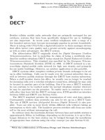
Wireless Local Area Networks
∗
Since the introduction of lightweight portable computers (laptops, notebooks),
a great deal of attention has been focused on the development of wireless
computer networks (Wireless Local Area Network, WLAN).
Thanks to standardization in the field of local area networks, it is com-
paratively easy to find systems that will still be upgradable even in a few
years’ time. Around 70 % of all computers connected to networks are compli-
ant with the IEEE 802.3 (Ethernet) and IEEE 802.5 (Token Ring) standards.
Connection is normally over a permanent wireline link. The problems that
can occur are the surfacing of mechanical defects (corrosion) after a few years
and violations of rules on radiated interference. It is difficult to adapt these
networks to cope with changing office conditions. Mobile network nodes are
not possible.
The obvious approach is to leave out the cable entirely. This idea is almost
as old as the concept of the so-called ALOHA system, which used radio to
connect terminals to their processing computers. The newer wireless LANs
work with the most up-to-date radio technology. Data is encrypted and ex-
tensive error-protection mechanisms are available. Integrity of data is also
guaranteed.
Just like wireline LANs, wireless LANs can be divided into different archi-
tectures and performance categories. Many companies offer products for wire-
less point-to-point connections, but only very few build LANs for multipoint
communication. Today wireless networks use spread-spectrum, narrowband
microwave or infrared signals for transmission (see Table 13.1). Because of
legal regulations, networks using spread-spectrum and narrowband microwave
cannot be operated in most countries unless special authorization has been
given.
Until now, wireless LANs have only had a very small share of the market.
This is partly due to the higher costs per network node, but no doubt also
because of the late standardization in this area. In spite of this, suppliers are
projecting a growth in wireless networks over the next few years. Standards
such as IEEE 802.11 or HIPERLAN/1 discussed below will help to increase
user acceptance of wireless LANs.
∗
With the collaboration of Christian Plenge and Andreas Hettich
Mobile Radio Networks: Networking and Protocols. Bernhard H. Walke
Copyright©1999 John Wiley & Sons Ltd
ISBNs: 0-471-97595-8 (Hardback); 0-470-84193-1 (Electronic)
656 13 Wireless Local Area Networks
Table 13.1: Characteristics of different transmission techniques
Spread spectrum Microwave Infrared
Frequency [GHz] 1–6 18.825–19.205 30 000
Range [m] 30–250 10–50 25
Power [W] <1 0.025 —
1
2
3
4
5
6
7 Application Layer
Presentation Layer
Transport Layer
Network Layer
Data Link Control Layer
Physical Layer
Session Layer
2b
2a
1
LLC
Logical Link Control
MAC
Media Access Control
Physical Layer
Higher Layers
Figure 13.1: The IEEE 802/ISO 8802 standard
13.1 Standards
The diversity of LAN systems in terms of cabling, transmission techniques,
transmission speeds, access procedures and variations thereof necessitated
standardization in order to facilitate their acceptance and enable different
LANs to work together.
Committee 802 of the Institute of Electrical and Electronics Engineers
(IEEE) in the early 1980s had developed a standard for Local Area Networks
(LANs) with speeds of up to 20 Mbit/s that offers security on the commu-
nications side for manufacturers as well as for users and has largely been
accepted.
The standard mainly restricts itself to the lower two layers of the ISO/OSI
reference model (see Figure 13.1). A separation is made between Logical Link
Control (LLC) and Medium-Access Control (MAC). The LLC layer upwardly
offers all systems a standard interface for establishing logical connections. The
MAC sublayer supports protocols such as token ring, token bus, CSMA/CD
(Ethernet).
In Western Europe the standards for wireless radio LANs are specified by
ETSI. The technical group RES 10 (Radio Equipment and Systems) at ETSI
has developed HIPERLAN/1, the European standard for wireless LANs [3].
13.2 Technical Characteristics of HIPERLAN/1 657
Table 13.2: Mid-frequencies of HIPERLAN/1
Channel No. Mid-frequency [MHz] Channel No. Mid-frequency [MHz]
0 5 176.4680 3 5 247.0562
1 5 199.9974 4 5 270.5856
2 5 223.5268
The frequency bands at 5.2 GHz and 17.1 GHz are being reserved throughout
Europe for this WLAN.
HIPERLAN Type 1 (HIPERLAN/1) describes a wireless LAN for com-
puter–computer/terminal communication. ETSI BRAN (Broadband Radio
Access Network, combining RES 10 and TM 4) also has workgroups that are
developing specifications for wireless ATM systems (Asynchronous Transfer
Mode) under the designation of HIPERLAN Type 2 (Wireless-ATM LAN),
HIPERACCESS (Wireless-ATM Remote Access) and HIPERLINK (Wireless-
ATM Interconnect). Results of their efforts are expected in 1998/99 (see
Section 12.1.5).
In parallel to the European HIPERLAN/1, the IEEE in the USA has spec-
ified 802.11 as an additional standard for WLANs [5].
Both standards are equipped with an IEEE 802.2 or ISO 8802 compat-
ible interface [6], allowing them to replace the wired transmission systems
described above. Because of the restriction of the radio medium (e.g., ra-
dio range), both standards must contain functions for the management and
maintenance of the radio network that far exceed the normal tasks of the
MAC sublayer. These are described along with the technical characteristics
of HIPERLAN/1 and IEEE 802.11 in the following sections.
13.2 Technical Characteristics of HIPERLAN/1
HIPERLAN/1 can be used as a universally accepted broadband and flexible
ad hoc LAN (see Section 13.3.1) and as such can be connected to other LANs.
Up to five frequency channels in the 5.15–5.30 GHz range are being provided
for HIPERLAN/1; see Table 13.2.
One channel provides a bit rate of 23.5294 Mbit/s for user and control
data. The data rate available to the user is reduced to 10–20 Mbit/s because
of the overhead added by the protocols of the different sublayers and the
channel-access procedure. At maximum 1 W transmitter power the range of
a HIPERLAN/1 node should be around 50 m indoors.
Three transmit and receive classes with varying power and sensitivity are
specified in the standard. A GMSK modulation method with a bandwidth
time product of 0.3 is used on the radio channel.
658 13 Wireless Local Area Networks
Synchronous applications as well as those with real-time requirements are
supported. The transmission time is not a critical factor with asynchronous
traffic, e.g., with electronic mail or file transfer.
The standard contains mechanisms for encryption of sensitive data before
it is sent.
HIPERLAN/1 terminals have to be small so they can be used in portable
computers. Plans are underway to make them available the size of a PCM-
CIA card (Personal Computer Memory Card Interface Association) with the
dimensions 85×54×10.5 mm (excluding antenna system).
Since HIPERLAN/1 systems support applications for battery-operated sys-
tems, they must offer low power consumption of a few hundred mW. HIPER-
LAN/1 offers an energy-saving mode.
HIPERLAN/1 networks should support the mobility of terminals. HIPER-
LAN/1 stations are therefore designed to be able to exchange information with
other stations at up to a speed of 10 m/s, which corresponds to 36 km/h, or
up to a rotational speed of 360➦/s.
13.3 Network Environments for HIPERLAN/1
The ETR 069 technical report [4] produced by the ETSI RES 10 commit-
tee defined the services and possibilities planned for HIPERLAN/1. Some of
the applications that will benefit from new solutions and an overview of the
HIPERLAN/1 network topologies are presented in the following [2]. HIPER-
LAN/1 appears without the “/1” below.
13.3.1 HIPERLAN Applications
Wireless offices A WLAN is a better option than a fixed network in listed
buildings or in environments where constructional changes are so fre-
quent that cabling cannot be installed, e.g., film and photographic stu-
dios. Furthermore, it should be possible, for example, to use portable
computers in different locations and connect them easily to a network.
Ad hoc networks Ad hoc networks are radio networks without any kind of
permanent communications infrastructure. A group of users can form its
own closed complex. This means that at conferences, conventions, and
large functions, or in the event of accidents or catastrophes, computers
can communicate with each other without having been cabled together
beforehand. Each user carries his part of the network with him in the
form of his computer with a radio-LAN connection.
Medicine Within a radio-LAN, doctors would be able to have direct and
interactive access to remote data such as X-rays when visiting their
patients. This would make the work of doctors easier and produce better
and faster diagnosis for patients.
13.3 Network Environments for HIPERLAN/1 659
CN
CN
CN
CN
CN
CN
CN
CN
...
...
B 1
B 2
B n-1
B n
A n-1
A n
A 2
A 1
Figure 13.2: Independent HIPERLANs
Industrial applications More and more work in industry is being automated.
In many cases the controlling computers are in a central facility man-
aging a large number of machines that are restricted to use in their
locations. A wireless connection to the network would allow these ma-
chines (e.g., industrial robots or unmanned vehicles) more freedom of
movement and the possibility of being used with more flexibility. Main-
tenance personnel would use laptops to retrieve the data needed for
diagnostic purposes.
13.3.2 Network Topologies
A HIPERLAN is not organized centrally, and instead has a completely dis-
tributed architecture with a dynamic allocation of network and network node
identifiers. Each station (node) is differentiated from the other stations by
a unique node identifier (NID). A number of stations are combined into a
network with a shared HIPERLAN identifier (HID). This network forms a
HIPERLAN.
In contrast to a wireline network, HIPERLANs using the same radio chan-
nel cannot be separated from one another. Overlapping can occur. Another
problem with radio channels is the range restriction. Mobile HIPERLAN
nodes and unfavourable propagation characteristics can cause the fragmenta-
tion of a network.
The following network topologies exist as a result of the channel character-
istics and the applications presented:
Independent HIPERLANs Two HIPERLANs, A and B, are considered to be
independent of each other if no member from HIPERLAN A is located
in the transmission range of a member from network B (see Figure 13.2).
Even if the same frequencies are used for transmission in both networks,
it is assumed that subnetworks A and B do not share the communica-
tion medium and therefore also do not cause any interference in each
other’s network. HIPERLAN A could be an ad hoc network set up for
660 13 Wireless Local Area Networks
CN
CN
CN
CN
CN
CN
CNCN
......
A n
B 1
B 2
B n
A 1
A 2
A n-1 B n-1
Figure 13.3: Overlapping HIPERLANs
a conference of company X, and HIPERLAN B an LAN used in the
factory of company Y.
Overlapping HIPERLANs If the radio range of some of the stations in net-
work A should overlap with some of the stations in network B then
these members share the communications medium and its transmission
capacity in the area where the overlapping occurs (see Figure 13.3).
An overlapping of networks produces two effects:
• The senders in the different HIPERLANs use the same frequency
band, thereby increasing the occurrences of interference. As a re-
sult, optimal use of the frequency band is no longer possible because
not all the stations are able to receive from each other (hidden sta-
tions) and therefore can cause interference.
• A station receives data packets from several HIPERLANs with dif-
ferent HIDs. All received data packets are evaluated, and only
those with their own HIDs are accepted. As a result, there is a
decrease in the maximum possible data transmission capacity and
consequently also the data transmission rate in this area.
These effects can be reduced if several frequency channels are introduced.
With HIPERLAN, up to five frequency channels in the 5.15–5.30 GHz
range are provided.
Multihop networks In addition to their original role as transmitting and re-
ceiving stations for their own terminals, some stations in a multihop
network also perform the function of relay stations. This allows data
to be transmitted over larger distances despite the restricted reachable
range of the radio medium. In Figure 13.4 the relay stations (forwarders)
2, 4 and 6 are forwarding the traffic of node 1 to destination 7.
Interworking Since most HIPERLAN applications already exist, it must be
possible for HIPERLANs to be connected to the usual fixed networks
13.4 HIPERLAN Reference Model 661
CN
CN CN
CN
CN
CN CN
A 7A 6A 3
A 4
A 5
A 2A 1
Figure 13.4: Communication in a multihop radio network
CN
CN CN
CN
CN
CN
CN
CN
CN
CN
CN
CN
CN
CN
CN
CN
CN
...
CN
A n-1
A n
A 2
A 1
...
B1
B 2
B n
B n-1
Figure 13.5: Connection to fixed network
(see Figure 13.5). This affects the network layer, and is not part of the
HIPERLAN/1 standard.
13.4 HIPERLAN Reference Model
The HIPERLAN reference model defines the components needed to install a
private radio subnetwork. It is based on the ISO/OSI reference model and
consists of the Medium-Access Control (MAC) sublayer, the Channel-Access
Control (CAC) sublayer and the physical layer; see Figure 13.6.
The organizational part of access is described in the MAC sublayer, access
to the radio channel takes place in the CAC sublayer. HIPERLAN provides
an ISO-8802 standard interface.
In accordance with the OSI service user/service provider model, each layer
provides services for the layer above it. These services are offered at the
662 13 Wireless Local Area Networks
Application Layer
Presentation Layer
Session Layer
Transport Layer
Network Layer
Data Link Layer
Physical Layer
Medium-Access Control
Sublayer
Physical Layer
Channel-Access Control
Higher Layer Protocols
Sublayer
Figure 13.6: ISO/OSI and HIPERLAN reference models
HCPDU
HIPERLAN CAC Sublayer
HC-Entity HC Entity
HCSAP HCSAP HIPERLAN CAC Service
HMPDU
HIPERLAN MAC Sublayer
HM-Entity HM Entity
MSAP MSAP HIPERLAN MAC Service
HIPERLAN Physical Layer
Figure 13.7: Service model for MAC and CAC sublayers
service access points between the layers, and are controlled by exchange of
service primitives (SP).
The individual sublayers are described in more detail in the following sec-
tions. Figure 13.7 shows the HIPERLAN service model.
13.5 HIPERLAN-MAC Sublayer
13.5.1 Tasks of the MAC Sublayer
The MAC sublayer provides the following functions to ensure smooth and
reliable HIPERLAN operation.
13.5.1.1 MAC Address Mapping
Because HIPERLAN stations share the radio channel, an overlapping of neigh-
bouring HIPERLANs can occur that causes the radio ranges of a number of
wireless networks to overlap in the same radio channel (see Figure 13.3).
13.5 HIPERLAN-MAC Sublayer 663
A restricted radio range, the mobility of the stations and unfavourable
propagation conditions can cause the fragmentation of a HIPERLAN (see
Figure 13.2), although A and B are separate subnetworks of the same HIPER-
LAN.
The standard defines internal address structures. A HIPERLAN address
consists of a HIPERLAN name (HID) and a station identification (NID). The
HID is used by the MAC protocol to differentiate between the MAC commu-
nication of the individual HIPERLANs. If there is a dynamic allocation of
the HID because of the possible overlapping of cells, it is less likely that mixed
communication will occur. The MAC protocol reserves the use of special HIDs
for communication between the stations of neighbouring HIPERLANs.
It is easier for a user to identify his network using a name rather than the
numerical HID. The name is also used by the lookup function for establishing
which HIPERLANs are operating in the area.
Since no clear guidelines and no administrative coordination exist for
HIPERLAN identification, it is possible for a MAC communication to take
place from non-distinguishable LANs. This situation is very unlikely, because
of the MAC identification scheme used.
The address mapping function converts IEEE-MAC addressing into HI-
PERLAN addressing.
13.5.1.2 Communication Security
A radio channel can be listened for in a neighbouring area. An encryption
algorithm with the appropriate cryptographic management is therefore pro-
vided in the MAC sublayer. This protects confidential data from unauthorized
eavesdropping, and also guarantees communication security for the radio net-
work.
The HIPERLAN encryption scheme provides for a common set of keys, one
of which is used in the encryption operation. Each key has a number that is
transmitted with the encrypted data to the receiver. In addition, a common
initialization vector for encryption and decryption is required and if necessary
transmitted.
The level of transmission security increases with the frequency of the change
of key and initialization vectors.
13.5.1.3 Addressing of Service Access Points
For compatibility with the ISO-MAC service definition the MAC service (HM
service) uses 48-bit LAN-MAC addresses for identification of MAC service
access points (MSAP) (see Figure 13.7). The standard recognizes separate
addresses for individual MAC service access points and group addresses for
contacting several MSAPs.
An HM entity is linked to a single MSAP, through which it offers MAC
services. It is also connected to a single HIPERLAN-CAC Service Access
Point (HCSAP), over which it uses the HIPERLAN-CAC services.
664 13 Wireless Local Area Networks
CN CN
CN CN
CN
CN
CN
CN
CN
CN
A 8
A 5A 4 A 6 A 7
A 9 A 10
A 1 A 2 A 3
Figure 13.8: Broadcast transmission
CNCN
CN
CN
CN CN
CN
CN
CN
CN
A 9 A 10A 8
A 7A 6A 5A 4
A 1 A 2 A 3
Figure 13.9: Unicast transmission
A single 48-bit LAN-MAC address is used as an MSAP address for ad-
dressing the service access point, the HM entity and the users of HIPERLAN-
MAC services. An address of the same length is used to identify a group of
MSAPs and the users associated with it.
13.5.1.4 Forwarding
The MAC protocol incorporates a multihop relaying facility that enables the
transmission of data beyond the boundaries of a station’s sending area—in
other words over several stations. An HM entity is either a forwarder or a
non-forwarder. Only forwarders carry out the forwarding of MSDUs when re-
quired. Point-to-point (unicast) as well as broadcast transmission (broadcast,
multicast) is possible for the transmission of packets.
Broadcast relaying is used to relay information to all HM entities or when
the transmission route is not known. Each station that recognizes a route to
the destination station forwards the data packet accordingly. To avoid data
packets from being routed by several stations at the same time, the protocol
ensures that only a limited number of stations can forward data. Figure 13.8
shows a broadcast transmission being sent by station 4.
It is more efficient to forward packets that are addressed to a particular
receiver if a unicast transmission is used (see Figure 13.9). A packet is then
routed to its destination through successive hops in accordance with an (op-
timal) route. Broadcast relaying must be used if the route is not known, as
explained above.
Each HM entity collects and manages routing information in its Routing
Information Base (RIB). This information is continuously updated. The data
in the RIB becomes obsolete and is discarded once it has passed its validity
period. Because of this constant updating of routing information, it is even
possible to specify quasi-optimal paths for the forwarding of packets in con-
tinuously changing HIPERLANs.
13.5 HIPERLAN-MAC Sublayer 665
HMS Provider
HIPERLAN-MAC Service MSAPMSAP
HMS User HMS User
Figure 13.10: HIPERLAN-MAC service model
13.5.1.5 Power Conservation Mechanisms
The power conservation function of the MAC protocol provides a power-saving
mechanism ensuring that battery-operated systems use a minimal amount of
power. The power-saving function is an optional function. It recognizes two
types of stations:
• The power-saving terminal (P-saver) defines time periods when it is
activated. These are the only times it sends and receives data.
• The P-supporter only transmits data to its power-saving neighbour when
the latter is activated.
13.5.2 MAC Services
As a service provider (HMS provider), the MAC sublayer provides its services
(HIPERLAN-MAC services, HMS) to the LLC sublayer above it at the MSAP.
This makes the LLC layer a HIPERLAN-MAC service user (HMS user) of
the services offered by the MAC sublayer (see Figure 13.10).
The following is defined for the transmission of MAC service data units
(MSDU):
• An MSDU is transmitted from the source MSAP to an individual des-
tination MSAP or to a group of destination service access points in a
single request to the MSDU transfer service. A connectionless service is
provided, i.e., the transfer takes place without the need for a connection
to be established explicitly and then later cleared.
• Each MSDU transmission is independent of all others.
• MSDUs are transmitted without any restriction to their content, format
or coding; MSDUs are never interpreted from the standpoint of their
structure or their content.
• An HMS user can indicate the quality of service desired (HIPERLAN-
MAC Quality of Service, HMQoS) using user priority and the MSDU
lifetime. Other means for influencing the HMS service provider are not
planned.
• The HMS provider can carry out the following actions:
666 13 Wireless Local Area Networks
Table 13.3: Range of values for quality of service parameters
Parameter
Allowable range of values
Default value
User priority 0 . . . 1 1
MSDU lifetime 0 . . . 32767 500
Residual lifetime 0 . . . 32767 —
– Discard MSDUs
– Duplicate MSDUs
– Change sequence of MSDUs
The HMS service provider notifies the HMS user through an HMQoS error
report that it was not possible to meet the desired quality of service for one
of the previous invocations of the MSDU transfer function.
HMS users can use the HIPERLAN lookup service to determine which
HIPERLANs are in their area.
13.5.2.1 MSAP Addresses
According to Section 13.5.1.3, there are two types of MSAP addresses:
• Individual MSAP addresses for the identification of an individual MSAP.
• Group MSAP addresses that address a group of MAC service access
points.
Individual MSAP addresses are allowed to be used as source and destination
address, but a group MSAP address can only be used to address a destination.
13.5.2.2 Quality of Service Parameters
When an MSDU is being transferred to User Data Acceptance (see Sec-
tion 13.5.3.4), a MAC service user can indicate the quality of service pa-
rameters (see Table 13.3):
User priority (UP) The UP indicates the importance of an MDSU. The user
priority controls the quality of service of time-critical services.
Lifetime of data This specifies the maximum lifetime of an MSDU that is
allowed to elapse between transmission and reception.
Residual lifetime This indicates how much time is still remaining from the
lifetime.
13.5 HIPERLAN-MAC Sublayer 667
Table 13.4: HMS primitives and their parameters
Task Service Primitive Parameter
Data
trans-
fer
MSDU transfer HM Unitdata req Source Address, Destina-
tion Address, MSDU, User
Priority, MSDU Lifetime
HM Unitdata ind Source Address, Destina-
tion Address, MSDU, User
Priority, MSDU Lifetime,
Residual MSDU Lifetime
Control HMQoS failure
report
HM Qosfailure ind Destination Address, User
Priority, MSDU Lifetime
HIPERLAN
lookup
HM Lookup req —
HM Lookup conf HIPERLAN Information
13.5.2.3 MAC Service Primitives
The HIPERLAN-MAC service primitives derived from the ISO/OSI stan-
dard represent the possible interactions between HMS user and HMS service
provider. The service primitives at the HIPERLAN-MAC service access point
and their parameters are listed in Table 13.4.
In addition to the quality of service parameters, the following parameters
are also used:
Source Address (SA) The individual sending address of the MSAP.
Destination Address (DA) Address of an individual MSAP or a group of
MSAPs to which a packet is directed.
MAC Service Data Unit (MSDU) Data that is transported without modifi-
cation by the HM service provider between HMS users. The size of the
packets is between zero and a value specified by the HMS provider.
HIPERLAN Information Information about other HIPERLANs in the vicin-
ity of an HMS user.
13.5.2.4 Description of Service Primitives in MAC Sublayer
MSDU Transmission If a data packet is ready for transmission, the MAC
sublayer is notified through an HM Unitdata Request message from the LLC
sublayer. All the information required for transmission to an MSAP or to a
group of MSAPs is supplied at the same time. The packet is regarded as being
independent of the previous or the following packets, and is transmitted in
connectionless mode. The receiver is not able to control the rate at which the
sender sends the packets. Figure 13.11 shows the primitives for a successful
transfer.
668 13 Wireless Local Area Networks
✂✁☎✄✝✆✟✞✝✠ ✡☞☛✝✌✍✡☞✌✍✄✏✎✒✑✝✓✍✔✍✑✝✕✖✡
✗✙✘ ✚✜✛✣✢ ✤✦✥✒✧★✛✪✩
✤✦✥✒✧★✛✪✩
✗✫✘ ✚✜✛✭✬
✂✁☎✄✝✆✂✞✍✠ ✡☞☛✝✌✍✡☞✌✍✄✏✮ ✞✍☛✍✠ ✯✖✌✝✡☞✠ ✰✍✞
N
N+1 +1N
✤✍✥✱✧★✛✟✩
Figure 13.11: Sequence of primitives in successful data transfer
✂✁ ✄✆☎✞✝ ✟✡✠☞☛✌☎✎✍
✟✡✠☞☛✌☎✎✍
✂✁ ✄✏☎✒✑
✓✕✔✗✖✡✘✕✙✡✚ ✛✢✜✡✣✡✛✤✣✥✖✧✦✩★✡✪✡✫✥★✡✬✭✛
✓✕✔✗✖✡✮✰✯✡✬✭✱✤✣✡✚ ✲ ✫✡✳✏★✥✖✧✴ ✙✡✜✥✚ ✵✶✣✥✛✤✚ ✯✥✙
+1
✟✡✠✧☛✌☎✷✍
N
N
N +1
Figure 13.12: Sequence of primitives in a detected failed data transfer
The LLC sublayer does not receive an acknowledgement indicating whether
the data packet has been successfully transmitted within the lifetime of the
MSDU.
HMQoS Error Report If an MSDU cannot be transmitted with the quality
of service prescribed by the user until the lifetime of the data is eliminated, the
MAC notifies the LLC sublayer through sending an HM Qosfailure Indication
that the transmission has failed. The MAC sublayer then discards the MSDU.
The error report gives the HMS user the chance to repeat the transmission
with adjusted quality of service parameters; see Figure 13.12.
13.5.3 HIPERLAN-MAC Protocol
Figure 13.13 presents an overview of the elements of the MAC sublayer, which
will be discussed in detail below.
User Data
Transfer
Function
Conservation
Function
Power
Routing
Information
Exchange
Function
Lookup
HIPERLAN
Function
HIPERLAN-MAC Service
HMPDU Transfer Function
HIPERLAN-CAC Service
HIPERLAN-
MAC
Sublayer
Figure 13.13: Structure of HIPERLAN-MAC sublayer
13.5 HIPERLAN-MAC Sublayer 669
The MAC protocol, which is a prerequisite for the services offered by
the HIPERLAN Channel-Access Control sublayer and introduced in Sec-
tion 13.6.2, is used in the MAC sublayer for communication between HM
entities. For the communication, HIPERLAN-MAC protocol data units (HM-
PDU) transmitted over an HC connection are exchanged between the HM
entities. For detection of the PDUs already received, each packet is assigned
a sequence number from the range 0–65 535.
Initiated by the HMS user—in other words spontaneously (for manage-
ment)—HMPDUs are created within the MAC sublayer. All HMPDUs are
collected in a queue, where they remain until they are transmitted or, because
of the expiration of their lifetime, are discarded.
The HIPERLAN-MAC protocol provides for service data units (HMSDU)
with maximum size 2385-byte length.
13.5.3.1 HIPERLAN Lookup Function
The lookup function is used to establish the communications environment of
a HIPERLAN. The following subfunctions are supported for this purpose:
Find A HIPERLAN known by its name can be found if the HIPERLAN
identifier (HID) associated with this name is established.
Create For the HIPERLAN name indicated, an HID that is not being used in
the current communications environment is selected for creating a new
HIPERLAN.
Destroy A HIPERLAN is implicitly destroyed if there is no user using its
HID.
Join A user implicitly joins a HIPERLAN by calling up its HID and the en-
cryption and decryption key used and sending his subsequent data pack-
ets using this HID.
Leave A user implicitly leaves a HIPERLAN when he no longer uses its HID
in his data packets and evaluates packets with this HID.
The lookup function is invoked after receipt of an HM Lookup Request ser-
vice primitive. It generates an LR-HMPDU addressed to all HIPERLAN
neighbours. A timer (T
lrr
) is started, and all responses from neighbouring
stations must arrive before it runs out (see Table 13.16).
All receivers of the LR-HMPDU create an LC-HMPDU addressed to the
sender of the LR-HMPDU. The HIPERLAN name and the HID of the HIPER-
LAN to which the station belongs are entered in this packet.
The information of all LC-HMPDUs which arrive at the HM entity before
the timer runs out is filed in a table. An HM Lookup Confirm service primitive
is used for forwarding this data to the HMS user making the inquiry. LC-
HMPDUs that arrive after the T
lrr
timer runs out are discarded.
670 13 Wireless Local Area Networks
13.5.3.2 Routing Information Exchange Function
The Routing Information Exchange Function enables HM entities to establish
a routing information base (RIB). The RIB contains lists in which neighbour-
ing relationships between two HM entities and information about individual
HM entities are administered. A differentiation is made between the following
data records:
• A neighbour tuple (N-tuple) with the MSAP address of a neighbour
and the neighbouring relationship to this station. All N-tuples together
form a neighbour table (N-table). N-tuples that contain neighbouring
forwarders are combined into a multipoint relay table (MRT). Whenever
there is a change to this list, the allocated sequence number (MRSC-
SN) is increased.
• Source multipoint relay tuples (SMR tuples) contain the MSAP address
and the MRSC-SN of a neighbour that is using this station as a for-
warder. All SMR tuples are combined into a source multipoint relay
table (SMR table).
• A topology tuple (T-tuple) contains the MSAP address of an HM entity
in the network, the corresponding MRSC-SN and the MSAP address of
the last hop on the route to this station. The corresponding list is the
topology table (T-table).
• The routing tuple (R-tuple) indicates to an HM entity the MSAP address
of the next station on the route to the HM entity and the total number
of hops required. All R-tuples together form a routing table (R-table).
The forwarder administers all the lists mentioned above for all known sta-
tions in the HIPERLAN; a non-forwarder only needs the SMR table.
The Routing Information Exchange Function allows an exchange of infor-
mation that enables communication beyond the boundaries of the radio area.
The procedures presented in the following sections enable stations to ascertain
their immediate neighbourhood and the configuration of the HIPERLAN.
Hello Procedure The Hello procedure is called up at regular intervals (T
hr
)
by the MAC sublayer for creating the neighbour table, the multipoint relay
table and the source multipoint relay table; see Table 13.16. In this connection
all N-tuples are entered in an H-MPDU, which is then sent to all neighbours.
The sequence number of the user’s own multipoint relay table along with the
station type (forwarder/non-forwarder) is also transmitted.
HM entities that receive an H-HMPDU adapt their MRT and N and SMR
tables according to the data contained in the information field. If an N-tuple
does not yet exist for the sender, one is produced. If the sender uses this
HM entity as a forwarder then an SMR tuple is created. A timer with T
hr
is
started for all data records that have been produced or changed, and when it
runs out, the expired N-tuples or SMR tuples are discarded (aging).
13.5 HIPERLAN-MAC Sublayer 671
Topology Control The topology control procedure allows the exchange of
information for the topology of the HIPERLAN. A TC-HMPDU is created by
an HM entity at fixed times (every T
tcr
) and whenever there has been a change
to the SMR table. It contains a list of the SMR tuples and corresponding
sequence number. The packet is sent to all HM entities, and should also be
forwarded by them. A timer with T
tcr
is started for all the list elements and
the appropriate tuple is destroyed after the timer has run out.
The receiver of a TC-HMPDU creates a T-tuple for each of the SMR tuples
contained in it or restores T-tuples that already exist. Because of the existing
T-tuples, the routing table is recalculated after any changes to the T-table.
If the maximum number of hops has not yet been reached and an R-tuple,
in other words a path, exists for the creator of the TC-HMPDU, the TC-
HMPDU is then forwarded with an increased hop timer.
Multipoint Relay Determination The MRT, in other words the subset of the
N-table that contains the forwarders important to this station is recalculated
at regular intervals (every T
hr
). If the MRT has changed, the corresponding
sequence number is increased and the topology control procedure is invoked.
13.5.3.3 Power Conservation Function
To save power, an HM entity (P-saver) is allowed to participate in the com-
munication process only at set times. The Power Conservation Function
provides the means for notifying other stations of the active and inactive peri-
ods. Certain stations serve as P-supporters whereby they delay the messages
for particular HM entities (unicast traffic). The supported stations must be
entered on the P-saver list administered by the P-supporter.
Wake Pattern Declaration Before a station initiates its power-saving oper-
ations, it sends a Wake Pattern Declaration packet (WPD-HMPDU). On the
packet it enters the time of the last wake state, the time interval between two
wake states and the duration of the state. This packet is transmitted to all
neighbouring stations.
After a P-supporter has received the packet, it adds the station with the
necessary parameters to the list of supported P-savers; in other words, it
adjusts the values. Each entry only has the lifetime T
wp
, and is then discarded.
Deferred Multicast Pattern Declaration (DMPD) To allow the deferred
reception also of broadcast traffic, the P-supporters define time intervals by
which they delay all received broadcast messages, thereby also allowing the
deferred reception of broadcast traffic. P-savers can participate through an
appropriate selection of their wake states.
For coordination of the broadcast traffic the P-supporter transmits a
ZDMPD-HMPDU at fixed intervals and before every deferred transmission.
672 13 Wireless Local Area Networks
It contains the time since the last transmission window, the time interval be-
tween two areas, and the duration of the state. This packet is sent to all
neighbouring stations.
After receipt of the DMPD packet, P-savers who are using the transmitting
times of the sender in order to receive multicast traffic adjust the duration
and the time for their next active state according to the values supplied.
A P-saver can also define additional wake states in order to participate in
the broadcast traffic. This involves a new entry in the corresponding list. The
validity of the entry expires after the time T
dmp
.
13.5.3.4 User Data Transfer Function
The User Data Transfer Function undertakes the transmission of data be-
tween two HMS users on the basis of the specified quality of service parameters
and in accordance with the existing routing information.
The MSDU is normally transferred from the HMS user to the HM entity.
Packed in a DT-HMPDU, the packet is passed from HM entity to HM entity
until it has reached its destination or the preset parameters (HMQoS) can no
longer be maintained. The destination HM entity forwards the MSDU to its
HMS users.
User Data Acceptance After an HM Unitdata Request has been made by
an HMS user, the User Data Acceptance function must decide whether it can
carry out the transmission with the quality of service requested. It either
accepts the MSDU or returns an error message. The criteria for the decision
could be average channel delays or other parameters which are not established
in the standard.
A DT-HMPDU is produced from the accepted MSDU and the quality-of-
service parameters (lifetime and user priority). The type of the DT-HMPDU
is determined through the destination address using the alias resolution pro-
cedure. Four different types are possible, DT0 (default type) to DT3, which
differ in the number of address fields they contain. The additional fields
contain alias addresses for MSAPs which are required for routing the DT-
HMPDUs (see also alias resolution). Parameters and timers for the PDUs
can be found in Section 13.8.
The routing function is called to forward the next HM entity on the route
to its destination.
HMQoS Error Report After the lifetime of one of these HMS users has
expired, the corresponding packet is discarded. The HMS user then receives
the appropriate error report.
User Data Delivery This function delivers received packets that are directed
to this HMS user. The MSDU is obtained from the DT-HMPDU and delivered
13.5 HIPERLAN-MAC Sublayer 673
Table 13.5: Selection of DT-HMPDU on basis of alias addresses
Alias address known for
HMPDU type Number and type
SA DA generated of address fields
— — DT0 2 (SA, DA)
× — DT1 3 (SA, ASA, DA)
— × DT2 3 (SA, DA, ADA)
× × DT3 4 (SA, ASA, DA, ADA)
with details about the quality of service achieved to the HMS user in an
HM Unitdata Indication primitive over the MAC service access point.
Alias Resolution The alias resolution function resolves the mapping that
may occur between alias addresses and MSAP addresses. This function is
necessary for routing DT-HMPDUs, generates DT-HMPDUs of the corre-
sponding type (DT0 to DT3) and sets the corresponding address fields.
Alias resolution is initiated by the user data acceptance function and the
forwarding function before the routing procedure determines the path of a
packet.
The alias table is searched for alias addresses for the source (SA) and
destination (DA) addresses. The alias source address (ASA) and the alias
destination address (ADA) are used to create new DT-HMPDUs with appro-
priately set address fields. Table 13.5 shows which DT-HMPDU is selected
depending on the alias address.
The alias learn function is invoked after each receipt of a DT-HMPDU
of the type DT1, DT2 or DT3 (these are the only ones that contain alias
addresses) for compiling and updating the alias tables. This function enters
alias combinations that are not yet known into its tables. All elements of the
alias table are subject to aging. They are discarded after expiration of the
time T
ah
.
Routing Based on the routing tuples, the routing function establishes the
address of the next HCSAP in order to reach the next HM entity as well
as the number of hops remaining on the path to the destination HM en-
tity. This function is invoked by the user data acceptance function after an
HM Unitdata Request and by the forwarding function. If no routing informa-
tion is available for the destination, the address of a neighbouring forwarder
is selected. If this also is not known, the reserved address for all adjacent
stations is used.
Forwarding If a DT-HMPDU that is not addressed to this HM entity is re-
ceived, the packet must be forwarded by a forwarder. The forwarding function
only accepts packets from a unicast transmission when the number of hops
674 13 Wireless Local Area Networks
Table 13.6: Mapping quality of service parameters to channel-access priority
Channel-access priority
NRML High UP Normal UP
NRML < 10 ms 0 1
10 ms ≤ NRML < 20 ms 1 2
20 ms ≤ NRML < 40 ms 2 3
40 ms ≤ NRML < 80 ms 3 4
80 ms ≤ NRML 4 4
does not exceed the maximum value and the last sender is entered in the
SMR table. The routing function is used to calculate the next hop and the
remaining number of hops for the packet.
13.5.3.5 HMPDU Transfer Function
The HMPDU transfer function sends MAC protocol data units between HM
entities. At the start of transmission, the data packet with the highest channel-
access priority is determined by the HMPDU transfer function to enable the
respective service to be provided with the quality of service requested.
The normalized residual MSDU lifetime, NRML is calculated from the resid-
ual lifetime of the HMPDUs and the number of hops still required to reach
the receiver.
NRML =
residual lif etime
number of hops
(13.1)
Channel-access priority is then generated from the NRML and the user pri-
ority UP as per Table 13.6 and is updated during each transmitting cycle.
HMPDU Selection This function selects the next packet to be transmitted
from the HMPDU queue according to the following rules:
• Select HMPDU(s) with the highest channel-access priority.
• From these select the one(s) with the lowest NRML.
• And then select any one of them.
Data where the residual lifetime has expired is not transmitted.
DT-HMPDU Encryption The content of the DT-HMPDU can be encrypted
through the selection of a key from the existing set for the coding of data
before transmission by the HMPDU transmission function while an HCSDU
(HIPERLAN-CAM service data unit) is being generated. The number of the
key used and the initialization vector are entered in the PDU.
13.6 HIPERLAN-CAC Sublayer 675
Taking the key number and the initialization vector, the receiver of a coded
DT-HMPDU can then decrypt the packet.
Checksums All PDUs are provided with a CRC32 checksum for the detection
of transmission errors.
HMPDU Transmission An HM entity can forward an HMPDU to the CAC
service provider for transmission whenever an HC Sync Indication primitive
exists or anytime after an HC Free Indication primitive (see Section 13.6.2.3).
This involves selecting the packet with the greatest penetration, per the pro-
cedure described above. Through an HC Unitdata Request primitive, the HM-
PDU is transferred with the necessary parameters to the CAC sublayer at the
HIPERLAN-CAC Service Access Point (HCSAP). Without any changes, the
HMPDU becomes the HCSDU. The end of the transmission is indicated by
HC Status Indication.
Upon receipt of a HC Data Indication primitive, the receiving HM entity
must accept the HCSDU received as an HMPDU and process it according to
its type or its destination.
13.6 HIPERLAN-CAC Sublayer
13.6.1 Tasks of CAC Sublayer
Channel-access takes place in the Channel-Access Control (CAC) sublayer
through a Channel-Access Mechanism (CAM). It is here that it is decided
during different phases which station has access to the radio channel to enable
it to send asynchronous or time-critical traffic over the physical layer to the
receiver. The CAC sublayer contains the functions described below.
13.6.1.1 Selection of HIPERLAN Radio Channel
Although the CAC protocol for multiple radio channel operation is defined,
channel selection is not specified in the standard.
13.6.1.2 Channel-Access Procedure NPMA
The MAC protocol expects the CAC sublayer with the CAM to provide a
hierarchical independent channel-access mechanism for the support of time-
critical traffic.
An expanded Non-Preemptive Priority Multiple-Access procedure (NPMA)
is used for HIPERLAN. This ensures that traffic with high priority is not
interrupted by traffic with a lower priority.
The NPMA procedure works in channel-access cycles on the radio channel.
An access cycle follows the preceding cycle or runs any time a channel is
considered to be available. Each transmission attempt is carried out according
676 13 Wireless Local Area Networks
✂✁☎✄✝✆✟✞✡✠☞☛✌✞✡✞✡☛✎✍✝✆
✏✒✑✔✓ ✕✟✑✔✓ ✖✗✓ ✘✚✙✛✖✗✓ ✕✝✜
✏✣✢✤✙✦✥★✧
✩
✕✟✜✤✖✪✧✟✜✤✖✗✓ ✕✝✜
✏✣✢✫✙✛✥★✧
✬
✍✝✆✦✭✯✮✟✆✦✭✯☛✌✍✝✆✱✰✲✮✝✞✡✍✝✳✎✴✦✭☎☛✎✍✟✆✵✶✁✷☛✎✍✝✁✷☛ ✭✹✸✺✰✲✮✝✞✡✍✝✳✌✴✦✭✯☛✌✍✝✆
✻✶✑✎✙✟✜✤✥✽✼✾✓ ✥★✥✽✓ ✕✟✜
✏✣✢✫✙✛✥★✧
Figure 13.14: Schematic sequence of an NPMA channel-access cycle
✂✁☎✄✝✆✟✞ ☎✠✡✞✝☛✌☞☎✍✎✆✟✏✒✑✓✁✔✆✝✁✕✄✌✖✘✗✚✙✜✛ ✢✣✖ ✒✁✔✄✝✆✤✞
✒✁☎✄✦✥✒✧★✖✩✗ ✒✁✔✄✪✥✂✧★✖✘✗
✒✁✔✄✪✞✌✗✚✫✬✙✜✛ ✭✮✖✘✗
Figure 13.15: HIPERLAN-CAC service model
to access priority, and is synchronized with the access cycles currently running
in the channel.
NPMA channel-access takes place in three phases as shown in Figure 13.14:
priority phase, contention phase and transmission phase.
During the priority phase, all stations that do not currently have the highest
priority are singled out. The access procedure is not interruptible, i.e, only
those stations that are ready at the beginning of the cycle are allowed to
attempt transmission. Otherwise they have to wait for the next cycle.
The priority phase is followed by the contention phase, during which only
those stations with sufficiently high priority participate. The procedure en-
sures that each station statistically has the same chance for a channel. HIPER-
LAN uses a two-tier contention phase.
All stations that were not eliminated then send their data packets. A
collision will occur if too many stations start to send at the same time.
13.6.2 CAC Services
As a HIPERLAN-CAC service provider (HCS provider) the CAC sublayer
provides its services (HIPERLAN-CAC services HCS) to the MAC sublayer
above it at the CAC service access point. In this case the MAC sublayer
is a HIPERLAN-CAC user (HCS user) of the services offered by the CAC
sublayer. A model illustrating this relationship is shown in Figure 13.15.
The following is defined for the transmission of HIPERLAN-CAC service
data units (HCSDUs):
• An HCSDU is transmitted from the source HCSAP to an individual
destination HCSAP or to a group of destination service access points in
a single request of the HCSDU transfer service. The MAC service user
can identify himself and submit one or more destination HCSAPs. The
13.6 HIPERLAN-CAC Sublayer 677
Table 13.7: Possible values for channel-access priority
Parameter Range of values Default value
Channel-access priority 0 . . . 4 4
service is a connectionless one, i.e., the transfer does not require that an
explicit connection be set up and then terminated again later.
• Each HCSDU transmission is independent of all the other ones.
• Activation of the HCSDU transfer service is controlled by the HC
provider according to the NPMA channel-access procedure.
• Each activation of the HCSDU transfer service is followed by an indica-
tion of whether or not the transmission was successful.
• An HCS user can provide the desired channel-access priority for the
transmission. Aside from these parameters the user has no influence on
the means used by the HCS service provider for the transmission.
• HCSDUs are transmitted without any restrictions in terms of content,
format or coding; HCSDUs are never interpreted from the standpoint of
their structure or content.
13.6.2.1 HCSAP Addresses
A HIPERLAN-CAC entity (HC entity) offers its services to a single HCS user
over a HIPERLAN-CAC service access point (HCSAP).
The result is that each HC entity is linked exactly to an HM entity. For
practical reasons the same individual 48-bit LAN-MAC address as for the
MSAP is used in addressing the HCSAP, the HC entity and the HCS user.
Similarly, the MSAP group address is used in the identification of a group
of HCSAPs and their service users.
13.6.2.2 HC Quality-of-Service Parameters
The only quality-of-service parameter known to the CAC service is channel-
access priority. This priority, which is defined in the NPMA, indicates the
relative importance of the CAC service data unit during access to a shared
channel (see Table 13.7). Numerically smaller values indicate a higher channel-
access priority.
13.6.2.3 HIPERLAN-CAC Service Primitives
Table 13.8 presents an overview of the service primitives that are possible at
the CAC service access point. The parameters required for transmission are
listed in the last column for each primitive.
678 13 Wireless Local Area Networks
Table 13.8: HCS primitives and their parameters
Function Service Primitive Parameter
Data
transfer
HCSDU
transfer
HC Unitdata Request (Source Address, Destination
Address HCSDU, HIPERLAN
Identifier, Channel Access Pri-
ority
HC Unitdata Indication (Source Address, Destination
Address HCSDU, HIPERLAN
Identifier)
Control Transfer
control
HC Sync Indication
HC Free Indication
HC Status Indication
—
—
(Transfer Status)
Table 13.9: Transmission status
Parameter Value Significance
Transfer Transfer Successful The HCSDU transmission was successful.
status Transfer Unsuccessful The HCSDU transmission was unsuccess-
ful. This status is also used when the HCS
provider is no longer prepared to carry out
an HCSDU transmission.
The following parameters are used in addition to channel-access priority:
Source address Individual address of the HCSAP sender.
Destination address Address of an individual HCSAP or a group of HCSAPs
to whom a packet is directed.
CAC service data unit Data not requiring modification by the HC service
provider that is transported between HCS users.
HIPERLAN identifier HID of destination HIPERLAN.
Transfer status Table 13.9 shows the possible status for the acknowledgement
of transmission by the HC Status Indication primitive.
13.6.2.4 Description of CAC Sublayer Service Primitives
Activation of the HCSDU transfer function by an HCS user is basically co-
ordinated by the transfer control function of the sublayer. This function is
used to notify the MAC sublayer when the CAC sublayer is ready to accept
an HCSDU to commence a channel-access cycle.
The HC service provider differentiates between two types of HCSDU trans-
fer. In a synchronized HCSDU transfer the transmissions directly follow each
13.6 HIPERLAN-CAC Sublayer 679
Layer N+1
Site B
Layer
t
t
HC_Unitdata_Indication
HC_Unitdata_Request
Site A
HC_Sync_Indication
HC_Status_indication
N +1NLayer
SYNC
SYNC
Figure 13.16: Sequence of primitives with
successful transmission over a synchronized
channel
Layer N+1 Layer N+1Layer N
t
t
SYNC
SYNC
Site BSite A
HC_Sync_Indication
HC_Unitdata_request
HC_Status_Indication
Figure 13.17: Sequence of primitives
with unsuccessful transmission over a
synchronized channel
other. In this situation channel-access may only commence directly after
transmission of the current packet has ended. This is necessary to ensure that
the NPMA channel-access procedure is functioning correctly. If a channel has
not been used for a longer period of time, transmission can begin immediately
after the HCSDU request. There is no synchronization with other transfers.
Every successful or unsuccessful transmission is acknowledged by the CAC
sublayer.
Synchronized HCSDU Transfer If there is only synchronized traffic al-
lowed, the CAC sublayer notifies the MAC sublayer accordingly through an
HC Sync Indication when the new channel-access cycle (t
SYNC
) begins. This
signals to the HCS user that the CAC sublayer can accept data for the fol-
lowing access cycle on the radio channel.
If the MAC sublayer has HCSDUs available for transmission, it must, as
soon as it receives the HC Unitdata Indication message, immediately create
an HC Unitdata Request primitive with the packet being sent to initiate the
HCSDU transfer. The HCSDU transfer function is not allowed to be invoked
at any other time. Figure 13.16 illustrates the sequence of primitives for a
successful transmission for synchronized access of the channel.
Owing to the channel-access mechanism, it is possible that an HCSDU
could not be transmitted because another station seized the channel or because
a collision occurred. This results in a negative acknowledgement of the transfer
request (see Figure 13.17).
HCSDU Transfer with Idle Channel Channel usage is not always so high
that the CAC sublayer has to synchronize itself. If the radio channel is Idle
for a longer period of time, the HCS provider notifies the MAC sublayer
accordingly through HC Free Indication. The CAC sublayer thereby indicates
that the HCS user can invoke the HCSDU transfer function at any time until
further notice. If there is a change to the channel status, the HCS user is
notified through an HC Status Indication.