Tài liệu Cutting Tools P12 pdf
Bạn đang xem bản rút gọn của tài liệu. Xem và tải ngay bản đầy đủ của tài liệu tại đây (214.81 KB, 10 trang )
www.toolingandproduction.com
Chapter 12/Tooling & Production
1
CHAPTER 12
Milling Cutters
and Operations
Metal Removal
Cutting-Tool Materials
Metal Removal Methods
Machinability of Metals
Single Point Machining
Turning Tools and Operations
Turning Methods and Machines
Grooving and Threading
Shaping and Planing
Hole Making Processes
Drills and Drilling Operations
Drilling Methods and Machines
Boring Operations and Machines
Reaming and Tapping
Multi Point Machining
Milling Cutters and Operations
Milling Methods and Machines
Broaches and Broaching
Saws and Sawing
Abrasive Processes
Grinding Wheels and Operations
Grinding Methods and Machines
Lapping and Honing
George Schneider, Jr. CMfgE
Professor Emeritus
Engineering Technology
Lawrence Technological University
Former Chairman
Detroit Chapter ONE
Society of Manufacturing Engineers
Former President
International Excutive Board
Society of Carbide & Tool Engineers
Lawrence Tech.- www.ltu.edu
Prentice Hall- www.prenhall.com
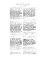
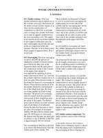
12.1 Introduction
The two basic cutting tool types used in the metal working industry are of the
single point and multi-point design, although they may differ in appearance and
in their methods of application. Fundamentally, they are similar in that the
action of metal cutting is the same regardless of the type of operation. By
grouping a number of single point tools in a circular holder, the familiar milling
cutter is created.
Milling is a process of generating machined surfaces by progressively remov-
ing a predetermined amount of material or stock from the workpiece witch is
advanced at a relatively slow rate of movement or feed to a milling cutter rotating
at a comparatively high speed. The characteristic feature of the milling process is
that each milling cutter tooth removes its share of the stock in the form of small
individual chips. A typical face milling operation is shown in Figure 12.1.
12.2 Types of Milling Cutters
The variety of milling cutters available for all types of milling machines helps
make milling a very versatile machining process. Cutters are made in a large
range of sizes and of several different cutting tool materials. Milling cutters are
made from High Speed Steel (HSS), others are carbide tipped and many are
replaceable or indexable inserts. The three basic milling operations are shown in
Figure 12.2. Peripheral and end milling cutters will be discussed below. Face
FIGURE 12.1: A typical milling operation; the on-edge insert design is being used.
(Courtesy Ingersoll Cutting Tool Co.)
Chap. 12: Milling Cutters & Operations
2
Tooling & Production/Chapter 12
www.toolingandproduction.com
milling cutters are usually indexable
and will be discussed later in this
chapter.
A high speed steel (HSS) shell
end milling cutter is shown in Fig-
ure 12.3 and other common HSS
cutters are shown in Figure 12.4
and briefly described below:
12.2.1 Periphery Milling
Cutters
Periphery milling cutters are usu-
ally arbor mounted to perform
various operations.
Light Duty Plain Mill: This
cutter is a general purpose cutter
for peripheral milling operations.
Narrow cutters have straight teeth,
while wide ones have helical teeth
(Fig. 12.4c).
Heavy Duty Plain Mill: A
heavy duty plain mill is similar to
the light duty mill except that it is
used for higher rates of metal removal.
To aid it in this function, the teeth are
more widely spaced and the helix angle
is increased to about 45
degrees.
Side Milling Cutter:
The side milling cutter
has a cutting edge on the
sides as well as on the
periphery. This allows the
cutter to mill slots (Fig.
12.4b).
Half-Side Milling Cut-
ter: This tool is the same
as the one previously de-
scribed except that cutting
edges are provided on a
single side. It is used for
milling shoulders. Two cutters of this
type are often mounted on a single
arbor for straddle milling.
Stagger-tooth Side Mill: This cut-
ter is the same as the side milling
cutter except that the teeth are stag-
gered so that every other tooth cuts on
a given side of the slot. This allows
deep, heavy-duty cuts to be taken
(12.4a).
Angle Cutters: On angle cutters,
the peripheral cutting edges lie on a
cone rather than on a cylinder. A
single or double angle may be provided
(Fig. 12.4d and Fig. 12.4e).
Shell End Mill: The shell end mill
has peripheral cutting edges plus face
cutting edges on one end. It has a hole
through it for a bolt to secure it to the
spindle (Fig. 12.3).
Form Mill: A form mill is a periph-
eral cutter whose edge is shaped to
produce a special configuration on the
surface. One example of his class of
tool is the gear tooth cutter. The exact
contour of the cutting edge of a form
mill is reproduced on the surface of the
workpiece (Fig.12.4f, Fig.12.4g, and
Fig.12.4h).
12.2.2 End Milling Cutters
End mills can be used on vertical and
horizontal milling machines for a vari-
ety of facing, slotting, and profiling
operations. Solid end mills are made
from high speed steel or sintered car-
bide. Other types, such as shell end
mills and fly cutters, consist of cutting
tools that are bolted or otherwise fas-
tened to adapters.
Solid End Mills: Solid end mills
have two, three, four, or more flutes
and cutting edges on the end and the
periphery. Two flute end mills can be
fed directly along their longitudinal
axis into solid material because the
cutting faces on the end meet. Three
Arbor
End mill
Spindle
Shan
k
Spindle
Milling
cutter
(a) (b) (c)
FIGURE 12.2: The three basic milling operations: (a) milling, (b) face milling, (c) end milling
FIGURE 12.3: High-speed steel (HSS) shell
end milling cutter. (Courtesy Morse Cutting
Tools)
(a) (b) (c) (d)
(e)(f)(g)(h)
FIGURE 12.4: Common HSS milling cutters: (a) staggered-tooth cutter, (b) side
milling cutter, (c) plain milling cutter, (d) single-angle milling cutter, (e) double-
angle milling cutter, (f) convex milling cutter, (g) concave milling cutter, (h) corner
rounded milling cutter.
www.toolingandproduction.com
Chapter 12/Tooling & Production
3
Chap. 12: Milling Cutters & Operations
and four fluted cutters with one
end cutting edge that extends past
the center of the cutter can also be
fed directly into solid material.
Solid end mills are double or
single ended, with straight or ta-
pered shanks. The end mill can be
of the stub type, with short cut-
ting flutes, or of the extra long
type for reaching into deep cavi-
ties. On end mills designed for
effective cutting of aluminum,
the helix angle is increased for
improved shearing action and
chip removal, and the flutes may
be polished. Various single and
double-ended end mills are
shown in Figure 12.5a. Various
tapered end mills are shown in
Figure 12.5b.
Special End Mills: Ball end
mills (Fig. 12.6a) are available
in diameters ranging from 1/32
to 2 1/2 inches in single and
double ended types. Single pur-
pose end mills such as Woodruff
key-seat cutters, corner rounding
cutters, and dovetail cutters
(Fig.12.6b) are used
on both vertical and
horizontal milling
machines. They are
usually made of high
speed steel and may
have straight or ta-
pered shanks.
12.3 Milling
Cutter
Nomenclature
As far as metal
cutting action is
concerned, the per-
tinent angles on
the tooth are those
that define the con-
figuration of the
cutting edge, the
orientation of the tooth face, and the
relief to prevent rubbing on the land.
The terms defined below and illus-
trated in Figures 12.7a and 12.7b are
important and fundamental to milling
cutter configuration.
Outside Diameter: The outside di-
ameter of a milling cutter is the diam-
eter of a circle passing through the
peripheral cutting edges. It is the
dimension used in conjunction with the
spindle speed to find the cutting speed
(SFPM).
Root Diameter: This diameter is
measured on a circle passing through
the bottom of the fillets of the teeth.
Tooth: The tooth is the part of the
cutter starting at the body and ending
with the peripheral cutting edge. Re-
placeable teeth are also called inserts.
Tooth Face: The tooth face is the
surface of the tooth between the fillet
and the cutting edge, where the chip
slides during its formation.
Land: The area behind the cutting
edge on the tooth that is relieved to
avoid interference is called the land.
Flute: The flute is the space pro-
vided for chip flow between the teeth.
Gash Angle: The gash angle is
measured between the tooth face and
the back of the tooth immediately
ahead.
Fillet: The fillet is the radius at the
bottom of the flute, provided to allow
chip flow and chip curling.
The terms defined above apply pri-
marily to milling cutters, particularly
to plain milling cutters. In defining
the configuration of the teeth on the
cutter, the following terms are impor-
tant.
Peripheral Cutting Edge: The cut-
ting edge aligned principally in the
direction of the cutter axis is called the
peripheral cutting edge. In peripheral
milling, it is this edge that removes the
metal.
FIGURE 12.5a: Various single- and double-
ended HSS end mills. (Courtesy The Weldon
Tool Co.)
FIGURE 12.5b: Various tapered HSS end mills.
(Courtesy The Weldon Tool Co.)
(a)
(b)
FIGURE 12.6: (a) Ball-nose end-milling cutters are
available in diameter ranging from 1/32 to 2 ½
inches. (Courtesy The Weldon Tool Co.) (b) HSS
dovetail cutters can be used on both vertical and
horizontal milling machines. (Courtesy Morse
Cutting Tools)
Tooth
Tooth face
Gash angle
Land
Flute
Fillet
O
utside diam
eter
Root diameter
Radial
rake angle
Peripheral
cutting edge
Secondary clearance
Primary clearance
(a)
(b)
Relief
FIGURE 12.7: Milling cutter configuration: (a) plain milling cutter
nomenclature; (b) plain milling cutter tooth geometry.
Chap. 12: Milling Cutters & Operations
4
Tooling & Production/Chapter 12
www.toolingandproduction.com
Face Cutting Edge: The face cut-
ting edge is the metal removing edge
aligned primarily in a radial direction.
In side milling and face milling, this
edge actually forms the new surface,
although the peripheral cutting edge
may still be removing most of the
metal. It corresponds to the end cut-
ting edge on single point tools.
Relief Angle: This angle is mea-
sured between the land and a tangent
to the cutting edge at the periphery.
Clearance Angle: The clearance
angle is provided to make room for
chips, thus forming the flute. Nor-
mally two clearance angles are pro-
vided to maintain the strength of the
tooth and still provide sufficient chip
space.
Radial Rake Angle: The radial
rake angle is the angle between the
tooth face and a cutter radius, mea-
sured in a plane normal to the cutter
axis.
Axial Rake Angle: The axial rake
angle is measured between the periph-
eral cutting edge and the axis of the
cutter, when looking radially at the
point of intersection.
Blade Setting Angle: When a slot
is provided in the cutter body for a
blade, the angle between the base of the
slot and the cutter axis is called the
blade setting angle.
12.4 Indexable Milling Cutters
The three basic types of milling opera-
tions were introduced earlier. Figure
12.8 shows a variety of indexable mill-
ing cutters used in all three of the basic
types of milling operations (Fig. 12.2).
There are a variety of clamping sys-
tems for indexable inserts in milling
cutter bodies. The examples shown
cover the most popular methods now in
use:
12.4.1 Wedge
Clamping
Milling inserts have
been clamped using
wedges for many years
in the cutting tool in-
dustry. This principle
is generally applied in
one of the following
ways: either the wedge
is designed and ori-
ented to support the in-
sert as it is clamped, or
the wedge clamps on
the cutting face of the
insert, forcing the insert
against the milling
body. When the wedge
is used to support the insert, the wedge
must absorb all of the force generated
during the cut. This is why wedge
clamping on the cutting face of the
insert is preferred, since this method
transfers the loads generated by the cut
through the insert and into the cutter
body. Both of the wedges clamping
methods are shown in Figure 12.9.
The wedge clamp system however,
has two distinct disadvantages. First,
the wedge covers almost half of the
insert cutting face, thus obstructing
normal chip flow while producing pre-
mature cutter body wear, and secondly,
high clamping forces causing clamp-
ing element and cutter body deforma-
tion can and often will result. The
excessive clamping forces can cause
enough cutter body distortion that in
some cases when loading inserts into a
milling body, the last insert slot will
have narrowed to a point where the last
insert will not fit into the body. When
this occurs, several of the other inserts
already loaded in the milling cutter are
removed an reset. Wedge clamping
can be used to clamp individual inserts
(Fig. 12.10a) or indexable and replace-
able milling cutter cartridges as shown
in Figure 25.10b.
12.4.2 Screw Clamping
This method of clamping is used in
conjunction with an insert that has a
pressed countersink or counterbore. A
torque screw is often used to eccentri-
cally mount and force the insert
against the insert pocket walls. This
clamping action is a result of either
offsetting the centerline of the screw
toward the back walls of the insert
FIGURE 12.8: A variety of indexable
milling cutters. (Courtesy Ingersoll
Cutting Tool Co.)
Insert
Support and
clamping
wedge
Clamping
wedge
FIGURE 12.9: Two methods of wedge clamping indexable
milling cutter inserts.
(a)
(b)
FIGURE 12.10: (a) Face milling cutter with wedge clamped indexable inserts.
(Courtesy Iscar Metals, Inc.) (b) Face milling cutters with indexable inserts and
wedge clamped milling cartridges. (Courtesy Greenleaf Corp.)
www.toolingandproduction.com
Chapter 12/Tooling & Production
5
Chap. 12: Milling Cutters & Operations
pocket, or by drilling and tapping the
mounting hole at a slight angle,
thereby bending the screw to attain the
same type of clamping action.
The Screw clamping method for
indexable inserts is shown in Figure
12.11.
Screw clamping is excellent for
small diameter end mills where space
is at a premium. It also provides an
open unhampered path for chips to
flow free of wedges or any other ob-
structive hardware. Screw clamping
produces lower clamping forces than
those attained with the wedge clamp-
ing system. However, when the cutting
edge temperature rises significantly,
the insert frequently expands and
causes
an unde-
sirable
retight-
ening ef-
fect, in-
creasing
the torque required to unlock the insert
screw. The screw clamping method can
be used on indexable ball milling cut-
ters (Fig. 12.12a) or on indexable in-
sert slotting and face milling cutters as
shown in Figure 12.12b.
12.5 Milling Cutter
Geometry
There are three industry standard mill-
ing cutter geometries: double negative,
double positive, and positive/negative.
Each cutter geometry type has certain
advantages and disadvantages that
must be considered when selecting the
right milling cutter for the job. Posi-
tive rake and negative rake milling
cutter geometries are shown in Figure
12.13.
Double Negative Geometry: A
double negative milling cutter uses
only negative inserts held in a negative
pocket. This provides cutting edge
strength for roughing and severe inter-
rupted cuts. When choosing a cutter
geometry it is important to remember
that a negative insert tends to push the
cutter away, exerting considerable
force against the workpiece. This
could be a problem when machining
flimsy or lightly held workpieces, or
when using light machines. However,
this tendency to push the work down,
or push the cutter away from the
workpiece may be benefi-
cial in some cases because
the force tends to ‘load’
the system, which often re-
duces chatter.
Double Positive Geom-
etry: Double positive cut-
ters use positive inserts
held in positive pockets.
This is to provide the
proper clearance for cut-
ting. Double positive cut-
ter geometry provides for
low force cutting, but the
inserts contact the
workpiece at their weakest
point, the cutting edge. In
positive rake milling, the
cutting forces tend to lift the
workpiece or pull the cutter
into the work. The greatest
advantage of double posi-
Insert
Insert
screw
FIGURE 12.11: Screw clamping method for
indexable inserts.
FIGURE 12.12: (a) Indexable-insert ball-nosed milling cutters using the screw clamping method.
(Courtesy Ingersoll Cutting Tool Co.) (b) Slotting cutters and face milling with screw-on-type
indexable inserts. (Courtesy Duramet Corp.)
(b)
(a)
Lead angle or corner angle or
peripheral cutting edge angle
Face or end
cutting edge
angle
Effective diameter
Side View
2-45°
Axial relief angle
Chamfer
or radius
Axial rake
angle (positive)
FCEA
2-4°
Effective diameter
Side View
Lead angle
2-4°
Axial relief angle
Chamfer 45°
Axial rake
angle (negative)
Wedge lock
Radial rake
angle (positive)
Bottom View
Peripheral or
radial relief angle
Wedge lock
Radial rake
angle (positive)
Bottom View
Peripheral
relief angle
FIGURE 12.13: Positive-rake and negative-rake face milling cutter
nomenclature.