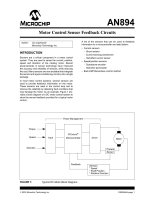
Motor control sensor feedback circuits
Bạn đang xem bản rút gọn của tài liệu. Xem và tải ngay bản đầy đủ của tài liệu tại đây (429.13 KB, 18 trang )
2003 Microchip Technology Inc. DS00894A-page 1
M
AN894
INTRODUCTION
Sensors are a critical component in a motor control
system. They are used to sense the current, position,
speed and direction of the rotating motor. Recent
advancements in sensor technology have improved
the accuracy and reliability of sensors, while reducing
the cost. Many sensors are now available that integrate
the sensor and signal-conditioning circuitry into a single
package.
In most motor control systems, several sensors are
used to provide feedback information on the motor.
These sensors are used in the control loop and to
improve the reliability by detecting fault conditions that
may damage the motor. As an example, Figure 1 pro-
vides a block diagram of a DC motor control system to
show the sensor feedback provided for a typical motor
control.
A list of the sensors that can be used to feedback
information to a microcontroller are listed below:
• Current sensors
- Shunt resistor
- Current-sensing transformer
- Hall effect current sensor
• Speed/position sensors
- Quadrature encoder
- Hall efect tachometer
• Back EMF/Sensorless control method
FIGURE 1: Typical DC Motor Block Diagram.
Author: Jim Lepkowski
Microchip Technology Inc.
Power Management
Input
Microcontroller
Driver
Motor
Feedback
Torque
Speed
Direction
Current
Sensor
Sensors
* Speed
* Shaft Position
* Rotation Direction
PICmicro
®
Motor Control Sensor Feedback Circuits
AN894
DS00894A-page 2 2003 Microchip Technology Inc.
CURRENT SENSORS
The three most popular current sensors in motor
control applications are:
• Shunt resistors
• Hall effect sensors
• Current transformers
Shunt resistors are popular current sensors because
they provide an accurate measurement at a low cost.
Hall effect current sensors are widely used because
they provide a non-intrusive measurement and are
available in a small IC package that combines the
sensor and signal-conditioning circuit. Current-sensing
transformers are also a popular sensor technology,
especially in high-current or AC line-monitoring
applications. A summary of the advantages and
disadvantages of each of the current sensors is
provided in Table 1.
Figure 2 shows an example of an AC motor powered by
a three-phase inverter bridge circuit. This example
shows that the composite current of all three Insulated
Gate Bipolar Transistor (IGBT) circuit legs can be
measured with a single shunt resistor, or that the
current in each individual leg can be determined with
three shunt resistors. Figure 2 shows a system that
uses shunt resistors. However, Hall effect and current-
sensing transformers can also be used to provide the
current measurement.
TABLE 1: COMPARISON OF CURRENT SENSING METHODS
FIGURE 2: AC Motor Current Measurement.
Current Sensing Method Shunt Resistor Hall Effect Current Sensing Transformer
Accuracy Good Good Medium
Accuracy vs.Temperature Good Poor Good
Cost Low High Medium
Isolation No Yes Yes
High Current-Measuring
Capability
Poor Good Good
DC Offset Problem Yes No No
Saturation/Hysteresis
Problem
No Yes Yes
Power Consumption High Low Low
Intrusive Measurement Yes No No
AC/DC Measurements Both Both Only AC
AC
Motor
V
DC
R
SENSE
V
OUT
R
SENSE_A
V
OUT_A
R
SENSE_B
V
OUT_B
R
SENSE_C
V
OUT_C
Current Measurement with
a Single Shunt Resistor
Current Measurement with
Three Shunt Resistors
I
A
I
B
I
C
I = I
A
+ I
B
+ I
C
AC
Motor
V
DC
I
A
I
B
I
C
2003 Microchip Technology Inc. DS00894A-page 3
AN894
Shunt Resistors
Shunt resistors are a popular current-sensing sensor
because of their low cost and good accuracy. The
voltage drop across a known low value resistor is
monitored in order to determine the current flowing
through the load. If the resistor is small in magnitude,
the voltage drop will be small and the measurement will
not have a major effect on the motor circuit. The power
dissipation of the resistance makes current shunts
impractical for measurements of more than
approximately 20 amperes.
The selection criteria of a shunt current resistor
requires the evaluation of several trade-offs, including:
• Increasing R
SENSE
increases the V
SENSE
voltage,
which makes the voltage offset (V
OS
) and input
bias current offset (I
OS
) amplifier errors less
significant.
• A large R
SENSE
value causes a voltage loss and a
reduction in the power efficiency due to the I
2
x R
loss of the resistor.
•A large R
SENSE
value will cause a voltage offset to
the load in a low-side measurement that may
impact the EMI characteristics and noise
sensitivity of the system.
• Special-purpose, low inductance resistors are
required if the current has a high-frequency
content.
• The power rating of R
SENSE
must be evaluated
because the I
2
x R power dissipation can produce
self heating and a change in the nominal
resistance of the shunt.
Special-purpose, shunt current measurement resistors
are available from a number of vendors. If standard
resistors are used, it is recommended that metal-film
resistors be used rather than wire-wound resistors that
have a relatively large inductance.
A shunt resistor can also be created from the trace
resistance on a PCB, as shown in Figure 3. PCB shunt
resistors offer a low cost alternative to discrete resis-
tors. However, their accuracy over a wide temperature
range is poor when compared to a discrete resistor.
The temperature coefficient of a copper PCB trace
shunt resistor is equal to approximately +0.39%/°C.
Further details on PCB trace resistors are given in ref-
erence (2).
.
FIGURE 3: PCB Shunt Resistor.
L
w
t
Trace resistance is based on:
* Length (L)
* Thickness (t)
* Width (w)
* Resistivity (ρ)
Example: What is the resistance of the PCB shunt resistor
Given: 1 oz Cu PCB
w = 50 mils (0.050 in)
L = 1 inch
L / w = number of squares ()
= 1 in / 0.050 in
= 20 squares
R ≈ (L / w) x R
≈ (20 squares) x 0.50 mΩ/
≈ 10 mΩ
R
PCB
* 1 oz. Copper (Cu) is defined to be a layer
with 1 oz. of Cu per square foot.
t ≈ 1.37 mil./oz. Copper
ρ ≈ 0.68 µΩ-inch
⇔
PCB Trace Resistor
using the parameters listed below?
P = I
2
x R
I = 5 ampere
= (5A)
2
x (0.010Ω)
= 0.25 Watt
R
≈ (0.50 mΩ / ) x [(1 oz. Cu) / (# oz. Cu)]
AN894
DS00894A-page 4 2003 Microchip Technology Inc.
High-Side vs. Low-Side Current Shunt
Measurements
SYSTEM INTEGRATION ISSUES
Shunt resistors can provide either a high-side or low-
side measurement of the current through the load, as
shown in Figure 4. A high-side monitor has the resistor
connected in series with the power source, while the
low-side monitor locates the resistor between the load
and the ground current return path. Both approaches
pose a trade-off to the designer. The attributes of the
two methods, along with the typical monitor circuits, will
be shown in the following sections. Reference (3)
provides more details on high-side and low-side
shunts.
High-side current measurements are the preferred
method from a system-integration standpoint because
they are less intrusive than low-side measurements.
The trade-off with the high-side measurement is that
the circuitry is more complex than the low-side method.
High-side resistive shunt measurements will not have a
significant impact on the system if the sensing resistor
is small and the resulting voltage drop across the shunt
is small compared to the supply voltage. In contrast,
low-side monitoring disrupts the ground path of the
load, which can cause noise and EMI problems in the
system.
Low-side current measurements are often chosen
because low voltage op amps can be used to sense the
voltage across the shunt resistor. Note that low-side
monitoring is not possible in some applications
because the ground connection is made via the
mechanical mounting of the motor on the chassis or
metal frame. For systems powered via a single wire
connection, it may not be practical to insert a shunt
resistor between the device and the chassis that
functions as the ground wire.
FIGURE 4: High-Side and Low-Side Resistive Current Shunts.
Measurement
Circuit
R
SENSE
I
LOAD
Measurement
Circuit
R
SENSE
I
LOAD
High-Side Current Measurement Low-Side Current Measurement
V
SENSE
V
SENSE
I
LOAD
= V
SENSE
/ R
SENSE
I
LOAD
= V
SENSE
/ R
SENSE
V
S
V
S
Load
+
-
Load
+
-
2003 Microchip Technology Inc. DS00894A-page 5
AN894
HIGH-SIDE CURRENT SHUNT
MEASUREMENTS
High-side current measurements can be implemented
with a differential amplifier circuit that produces an
output voltage that is proportional to V
SENSE
or the
current flowing through the load. Figure 5 provides an
example of a high-side shunt circuit. The differential
amplifier circuit can be implemented with an op amp
and discrete resistors or with an integrated IC device.
Integrated differential amplifier ICs are available from a
number of semiconductor vendors and offer a
convenient solution because the amplifier and well-
matched resistors are combined in a single device.
The attributes of high-side monitoring are listed below:
Advantages:
• Less intrusive than low-side monitors and will not
affect the EMI characteristics of the system.
• Can detect overcurrent faults that can occur by
short circuits or inadvertent ground paths that can
increase the load current to a dangerous level.
• A differential amplifier circuit will filter undesirable
noise via the common-mode-rejection-ratio
(CMRR) of the amplifier.
• A resistive network can be used to reduce the
voltage at the amplifier’s input terminals. For
example, if R
IN
= R*, the input voltage will be
reduced in half and the amplifier will be biased at
V
S
/2. Note that the amplifier gain will be equal to
one and that a second amplifier may be needed to
increase the sensor’s output voltage.
Disadvantages:
•The V
SENSE
voltage is approximately equal to the
supply voltage, which may be beyond the
maximum input voltage range of the operational
amplifier.
• A differential amplifier’s CMRR will be degraded
by mismatches in the amplifier resistors.
• The input impedance of the differential circuit is
relatively low and is asymmetrical. The input
impedance at the amplifier’s non-inverting input is
equal to R
IN
+ R*, while the impedance at the
inverting terminal is equal to R
IN
.
• May require rail-to-rail-input op amps because of
the high voltage level of the input signal.
The high-side shunt circuit requires a high-voltage
amplifier that can withstand a high common mode
voltage. In addition, the key amplifier specifications are
a high CMRR and a low V
OS
because of the relatively
small magnitude of V
SENSE
. High voltage op amps and
integrated differential amplifier ICs are available for
systems that have a maximum voltage of
approximately 60V. For voltage requirements beyond
60V, a current mirror circuit can be used to sense the
current. A current mirror can be implemented with
readily available, high-voltage transistors. References
(1) and (5) provide examples of high-voltage, high-side
current monitor circuits.
Table 2 provides a list of the recommended Microchip
op amps that can be used in a high-side circuit.
FIGURE 5: High-Side Resistive Current Measurement Circuit.
TABLE 2: RECOMMENDED MICROCHIP OP AMPS FOR HIGH-SIDE CURRENT SHUNTS
Product Operating Voltage CMRR (Typ.) V
OS
(Max.) Features
TC7652 6.5 to 16V 140 dB 10 µV • Low Noise
• Chopper Stabilized
TC913A 6.5 to 16V 116 dB 15 µV • Auto-zeroed Op Amp
TC913B 6.5 to 16V 110 dB 30 µV • Auto-zeroed Op Amp
R
SENSE
I
LOAD
ADC
PICmicro
®
V
OUT
= V
SENSE
x (R*/R
IN
)
V
OUT
R*
R*
R
IN
V
SENSE
= (I
LOAD
x R
SENSE
) x (R*/R
IN
)
V
S
R
IN
+
-
Load
Micro-
controller
AN894
DS00894A-page 6 2003 Microchip Technology Inc.
LOW-SIDE CURRENT MEASUREMENT
Low-side current measurements offer the advantage
that the circuitry can be implemented with a low voltage
op amp because the measurement is referenced to
ground. The low-side measurement circuit can use a
non-inverting amplifier, as shown in Figure 6.
The low-side current monitor can also be implemented
with a differential amplifier. The advantages of
differential amplification are limited because R
SENSE
is
connected to ground and the common mode voltage is
very small. Note that integrated IC low-side monitors
that combine the op amp and resistors are not readily
available because of the simplicity of the circuit that can
be implemented with a few discrete resistors and low
voltage op amp.
The attributes of low-side monitoring are:
Advantages
•V
SENSE
is referenced to ground. Therefore, a low
voltage amplifier can be used.
• A non-inverting amplifier can be used and the
input impedance of the circuit will be equal to the
large input impedance of the amplifier.
Disadvantages
• The low-side resistor disrupts the ground path
and the added resistance to the grounding system
produces an offset voltage which can cause EMI
noise problems.
• Low-side current monitors are unable to detect a
fault where the load is accidently connected to
ground via an alternative ground path.
Table 3 provides a list of the recommended Microchip
op amps that can be used in a low-side circuit. The key
op amp specifications for selecting a low-side amplifier
are rail-to-rail input and a low offset voltage (V
OS
).
FIGURE 6: Low-Side Resistive Current Measurement Circuit.
TABLE 3: RECOMMENDED MICROCHIP OP AMPS FOR LOW-SIDE CURRENT SHUNTS
Product Operating Voltage CMRR (Typ.) V
OS
(Max.) Features
TC913A 6.5 to 16V 116 dB 15 µV • Auto-zeroed Op Amp
TC913B 6.5 to 16V 110 dB 30 µV • Auto-zeroed Op Amp
MCP606 2.5 to 5.5V 91 dB 250 µV • Rail-to-Rail Output
• Low Operating Current
MCP616 2.3 to 5.5V 100 dB 150 µV • Rail-to-Rail Output
• Low Operating Current
+
-
R
SENSE
I
LOAD
ADC
PICmicro
®
V
OUT
V
SENSE
V
S
R
1
R
2
Microcontroller
V
OUT
= (V
SENSE
) x (1 + R
2
/R
1
)
= (I
LOAD
x R
SENSE
) x (1 + R
2
/R
1
)
Load
2003 Microchip Technology Inc. DS00894A-page 7
AN894
SHUNT OFFSET ADJUSTMENT CIRCUIT
The circuit shown in Figure 7 can be used to provide an
offset to the amplification of the V
SENSE
signal.
Resistor R
1
is used to prevent the offset voltage
provided by resistors R
4
and R
5
from changing the
value of V
SENSE
. The offset can be used to center the
amplifier’s output to the midpoint of the voltage supply
(V
DD
/2). The V
SENSE
signal is typically only 10 to
100 mV above ground and the offset often is needed if
the amplifier is connected to an ADC.
FIGURE 7: Shunt Offset Adjustment
Circuit.
Providing an offset to the shunt resistor circuit can also
improve the linearity of the amplification, especially if
standard op amps are used. The linearity, accuracy
and power consumption of a standard single power
supply op amp is typically degraded when the output
signal is at, or near, the power supply rails. Thus, the
offset circuit can be used to avoid this problem. The
preferred op amps to use in a shunt circuit have a small
offset voltage (V
OS
) and a rail-to-rail, input-output
specification.
NOISE REDUCTION TECHNIQUES
The combination of a differential amplifier with a high
CMRR and discrete RC filters can be used to minimize
the effect of EMI noise. The effect of EMI on a
measurement typically results in poor DC performance
and a large DC offset at the output of the op amp.
Figure 8 provides an example of a circuit that can be
used in a motor application to reduce noise.
The addition of the common mode filters formed by the
RC combinations of R
1
C
1
and R
2
C
2
are used to reduce
the noise that is imposed on the two input lines of the
amplifier. Discrete RC networks lower the voltage level
of the noise signal by functioning as a low pass filter.
However, an EMI filter, such as a TVS zener diode, is
required to ensure that the input noise is clamped to a
safe voltage level that will not damage the amplifier.
The common mode resistors and capacitors should be
matched as close as possible. The resistors should
have a tolerance of 1% or better, while the capacitors
should have a tolerance of 5% or better. Capacitor C
3
is used to add a RC differential filter that compensates
for any mismatch of R
1
C
1
and R
2
C
2
. Any difference in
the RC combinations will result in a degradation of the
amplifier’s CMRR. The differential filter formed by R
1
C
3
and R
2
C
3
will attenuate the differential signal at the
amplifier caused by the tolerances of the common
mode filters.
FIGURE 8: RC Noise Reduction Circuit.
V
DD
V
OUT
V
SENSE
R
1
R
SENSE
I
LOAD
V
DD
R
4
R
5
V
OUT
= [(V
SENSE
(1 + (R
3
/R
2
)) + ((R
5
/ (R
4
+R
5
)V
DD
)]
Amplifier Gain = (1 + (R
3
/ R
2
))
R
2
R
3
Load
V
S
R
SENSE
<< R
1
V
OUT
R
1
R
2
R
SENSE
I
LOAD
C
1
C
2
C
3
R
1
= R
2
C
1
= C
2
C
3
>> C
1
and C
3
>> C
2
Common Mode Filter
f
-3dB
= 1 / (2π R
1
C
1
)
= 1 / (2π R
2
C
2
)
Differential Mode Filter
f
-3dB
=1/ [2π (R
1
+R
2
) (((C
1
x C
2
)/(C
1
+C
2
)) + C
3
)]
Load
V
S
R
4
R
3
R
SENSE
<< R
1
and R
2
AN894
DS00894A-page 8 2003 Microchip Technology Inc.
Figure 9 provides an example of a shunt amplifier
circuit that combines the filtering of the shunt current
signal with an offset adjustment. The RC components
R
1
C
1
, R
2
C
2
and C
3
are used to provide EMI and ESD
protection to the amplifier. The RC feedback networks
of R
7
C
5
and R
6
C
4
are selected to provide a low pass
filter response to the differential amplifier.
A trade-off with discrete filter networks is that the
frequency response of the filter is dependent on the
source and load impedance. The filter equations shown
are only an approximation. A more detailed analysis or
SPICE simulation may be required to accurately model
the filter response of the circuit.
FIGURE 9: Combining the Offset and
Noise Reduction Circuit.
Integrated EMI filters can be used to simplify the circuit
shown in Figure 9 and reduce the number of discrete
components. Integrated Passive Device (IPD) EMI
filters that consist of resistors and transient
suppression (TVS) zener diodes are available from a
number of IC venders. IPD filters integrate the discrete
components in a small IC package, while providing
transient voltage protection.
TVS devices offer the advantage that the input signal is
clamped to a safe value that is equal to the breakdown
voltage of a zener diode. The zener diode functions as
a capacitor when the voltage is below the breakdown
voltage. Thus, the IPD filter is equivalent to a RC filter
when the input voltage is small. Further details on IPD
EMI filters and ESD protection devices are provided in
reference (8).
Hall Effect Current Sensors
Hall effect sensors are a current-measuring sensor that
can be easily integrated into an embedded application.
Several vendors offer devices that combine the
magnetic sensor and conditioning circuit in a small IC
package. These IC sensors typically produce an
analog output voltage that can be input directly into the
microcontroller’s ADC. The main disadvantages of Hall
effect current sensors are that they are expensive and
their accuracy varies with temperature.
The Hall effect is based on the principle that a voltage
(V
H
) is created when current (I
C
) flows in a direction
perpendicular to a magnetic field (B), as shown in
Figure 10. Hall effect current sensors are available in
either an open-loop or closed-loop implementation.
The closed-loop Hall effect sensors offer the advantage
that their output linearity is better than an open-loop
sensor over a wider current measurement range.
Further details on Hall effect sensors are available in
references (4), (7) and (12).
FIGURE 10: Hall Effect Principle.
The Hall effect current sensor can be placed on the
PCB directly over the current trace that will be
monitored. The sensor functions by measuring the
magnetic flux that is created by the current flowing
through the trace. Figure 11 provides an example of a
PCB mounted Hall effect sensor that measures the
current through a wire placed on the top of the IC. Hall
effect current sensors are also available in a package
that is mounted on the PCB, with the current-carrying
wire passing through a hole in the sensor.
FIGURE 11: Hall Effect Current Sensor.
V
OUT
R
1
R
2
R
SENSE
I
LOAD
C
1
C
2
C
3
R
1
= R
2
= R
IN*
R
IN
>> R
IN*
C
1
= C
2
V
DD
V
DD
R
7
R
6
C
5
DC Amplifier Gain = -R
F
/ (R
IN*
+ R
IN
)
Amplifier Feedback Low Pass Filter
R
5
V
OUT
= [((I
LOAD
x R
SENSE
) x (R
F
/(R
IN
+ R
IN*
))
+ ((R
6
/(R
5
+R
6
)V
DD
)]
C
3
>> C
1
and C
3
>> C
2
f
-3dB
@ 1 / (2π R
F
C
F
)
R
3
R
4
C
4
C
4
= C
5
= C
F
EMI Filter
R
3
= R
4
= R
IN
R
7
= R
5
ll R
6
= R
F
Load
V
S
R
SENSE
<< R
1
and R
2
I
C
I
C
V
H-
V
H+
B
I
I
Printed Circuit Board
2003 Microchip Technology Inc. DS00894A-page 9
AN894
Current-Sensing Transformers
Current-sensing transformers offer an alternative to
shunt resistors and Hall effect sensors to measure cur-
rent. These sensors use the principle of a transformer,
where the ratio of the primary current to the secondary
current is a function of the turns ratio. The main advan-
tage of current transformers is that they provide gal-
vanic isolation and can be used in high-current
applications. The main disadvantage of current trans-
formers is that an AC input signal is required to prevent
the transformer from saturating.
Figure 12 provides schematics of a single turn and a
multi-turn primary current-sensing transformers. The
single-turn primary transformer offers the advantage
that the measurement is non-intrusive and the current-
carrying wire can be passed directly through a hole in
the transformer. The multi-turn transformer offers the
advantages of improved magnetic coupling, since
many turns of the primary wire can be provided.
FIGURE 12: Current-Sensing Transformers.
N
p
N
s
R
t
I
p
I
s
+
-
V
OUT
I
s
= I
p
/ N where N = turns ratio
V
OUT
= I
s
x R
t
N
p
N
s
R
t
I
p
I
s
+
-
V
OUT
Single-Turn Primary
1
2
Multi-Turn Primary
B
A
1
2
3
4
A
B
I
p
1
2
2
1
4
3
AN894
DS00894A-page 10 2003 Microchip Technology Inc.
BACK EMF CONTROL METHOD
The back electro-magnetic-force (EMF) or sensorless
motor control method obtains the speed and position of
the motor directly from the voltage at the motor
windings. This method is typically used in brushless DC
motors to provide commutation. The back EMF control
method eliminates the requirement for relatively expen-
sive sensors, such as Hall effect devices. The back
EMF voltage produces a sine or trapezoidal waveform
that is sensed at the motor’s winding and typically is
converted into a digital square wave by a zero-crossing
comparator circuit. The comparator signal is inputted to
the microcontroller, which calculates the commutation
sequence and motor position from the phase
relationship of the square wave representation of the
back EMF signals.
The back EMF is created when the motor’s armature
turns, which creates a electrical kickback or EMF that
is sensed as a voltage through a resistor. The
amplitude of the EMF signal increases with the speed
of the armature rotation. A limitation of the back EMF
method is that the amplitude of the signal is very small
at low shaft RPMs.
The zero-crossing circuit can be constructed from
either discrete comparator ICs or comparators that are
located inside the PICmicro
®
microcontroller. Figure 13
provides a block diagram of a sensorless control for a
Brushless Direct Current (BLDC) motor that uses
discrete comparator circuits.
FIGURE 13: Block Diagram of a Sensorless BLDC Motor Control.
3-Phase
Inverter Bridge
PIC18FXX31
PWM5
PWM4
PWM3
PWM2
PWM1
PWM0
A
C
B
V
REF_A
BACK EMF
ZERO-CROSSING
COMPARATOR CIRCUITS
V
DC
V
DC
V
DC
V
DC
BEMF
A
BEMF
B
BEMF
C
V
REF_B
V
REF_C
2003 Microchip Technology Inc. DS00894A-page 11
AN894
SELECTING A COMPARATOR
A comparator is designed to provide a logic-level
output signal that indicates whether the voltage at the
non-inverting input is larger or smaller than the voltage
at the inverting input. Figures 14 and 15 show the cir-
cuit topology and design equations for a non-inverting
and inverting comparator, respectively. The non-invert-
ing circuit’s output is in phase with the sinewave input,
while the inverting circuit that has an output 180° out of
phase from the input signal. Reference (6) provides
further details on the comparator voltage transition and
hysteresis equations.
For example, the output voltage of a single voltage
supply, non-inverting comparator will be analyzed. The
output will be the same for a push-pull or an open-drain
output device that is connected to voltage V
DD
through
a pull-up resistor. If the voltage at the non-inverting (+)
terminal is larger than the voltage at the inverting (-)
terminal, the output will be equal to approximately V
DD
.
In contrast, if the voltage at the (+) terminal is less than
the voltage at the (-) terminal, the output will be equal
to approximately V
SS
or ground.
Though op amps can be used as a comparator, the
designer must consider the trade-offs of using an
amplifier in a non-linear mode. Op amps are designed
to linearly amplify a small signal and use negative
feedback to function in the linear region. By contrast,
comparators are designed to function in the non-linear
region and use positive feedback to force the output to
have a fast transition to the saturation region where the
output is at either the high or low power supply rail.
Though op amps can function as a comparator by
using positive feedback, the switching speed of the cir-
cuit is typically poor. The propagation delay of an op
amp comparator is large in comparison with a typical
comparator. In addition, the current consumption of an
op amp comparator usually is much larger than a
standard comparator.
Table 4 provides a list of recommended Microchip
comparators. A key specification for motor control
applications is the propagation delay of the comparator.
TABLE 4: RECOMMENDED MICROCHIP COMPARATORS
Product
Operating
Voltage
I
Q
(Typ.)
Propagation Delay
(typ.)
Features
TC1025 1.8 to 5.5V 8 µA 4 µs • Rail-to-rail input and output
TC1027
TC1028
1.8 to 5.5V
1.8 to 5.5V
18 µA
10 µA
4µs
4µs
• On-board V
REF
• Shutdown pin (TC1028)
TC1031 1.8 to 5.5V 6 µA 4 µs • Prog. Hysteresis
• Shutdown pin
• On-board V
REF
TC1037
TC1038
TC1039
1.8 to 5.5V
1.8 to 5.5V
1.8 to 5.5V
4µA
4µA
6µA
4µs
4µs
4µs
• Shutdown pin (TC1038)
• On-board V
REF
(TC1039)
TC1040
TC1041
1.8 to 5.5V
1.8 to 5.5V
10 µA
10 µA
4µs
4µs
• On-board V
REF
• Prog. Hysteresis (TC1041)
MCP6541/2/3/4 1.6 to 5.5V 0.6 µA
per comparator
4µs • Low I
Q
• Push-pull output
MCP6546/7/8/9 1.6 to 5.5V 0.6 µA
per comparator
4µs • Low I
Q
• Open-drain output
AN894
DS00894A-page 12 2003 Microchip Technology Inc.
FIGURE 14: Single Supply Non-Inverting Comparator Circuit.
FIGURE 15: Single-Supply Inverting Comparator Circuit.
V
DD
V
DD
V
PULL-UP
V
OUT
V
IN
V
OH
V
OL
V
TL
V
TH
V
IN
V
OUT
V
REF
R
2
R
3
R
4
R
PULL-UP
Design Procedure:
1. Select V
REF
, the “zero-crossing” voltage
Hysteresis Plot
From
Motor Windings
2. Select V
HYS
to be equal to 10 to 100 mV
3. Select R
3
>> R
1
Note: R
PULL-UP
is required for open drain outputs,
but is not required for push-pull output comparators.
Assume: V
OH
= V
DD
, V
OL
= 0, R
3
>> R
1
and R
3
>> R
PULL-UP
V
REF
V
DD
R
4
R
2
R
4
+
×=
V
TL
R
1
R
3
+()V
REF
R
1
V
DD
×()–
R
3
≅
V
TH
R
1
R
3
+()V
REF
R
3
≅
V
HYS
V
TH
V
TL
–=
V
HYS
R
1
R
3
V
DD
×≅
V
M
R
1A
R
1B
V
IN
R
1B
R
1A
R
1B
+
V
M
×= R
1
R
1A
R
1B
||
=
V
DD
V
DD
V
PULL-UP
V
OUT
V
IN
V
OH
V
OL
V
TL
V
TH
V
IN
V
OUT
R
1
R
2
R
3
R
PULL-UP
Design Procedure:
1. Select V
REF
, the “zero-crossing” voltage
Hysteresis Plot
V
REF
2. Select V
HYS
to be equal to 10 to 100 mV
Assume: V
OH
= V
DD
, V
OL
= 0, R
3
>> R
1
ll R
2
and R
3
>>R
PULL-UP
Note: R
PULL-UP
is required for open drain outputs,
but is not required for push-pull output
3. Select R
3
>> R
1
ll R
2
From
Motor Windings
V
REF
V
DD
R
1
R
1
R
2
+
×≅
V
TL
R
1
R
1
R
2
+
V
DD
×≅
V
TH
R
1
R
1
R
2
+
V
DD
×
R
1
R
2
||
()V
DD
×
R
3
+≅
V
HYS
R
1
R
2
||
()V
DD
×
R
3
≅
V
HYS
V
TH
V
TL
–=
V
IN
R
1B
R
1A
R
1B
+
V
M
×= R
1
R
1A
R
1B
||
=
V
M
R
1A
R
1B
comparators.
2003 Microchip Technology Inc. DS00894A-page 13
AN894
COMPARATOR REFERENCE VOLTAGE
In single supply comparators, a reference voltage must
be created. The circuits create V
REF
by using a resistor
voltage divider. The offset voltage of V
REF
enables the
circuit to function as a zero-crossing detector without
requiring a dual voltage power supply. The back EMF
voltage produces a sine or trapazoidal waveform that
swings above and below power ground. The back EMF
voltage can be sensed as a sine or trapazoidal wave-
form offset by a DC voltage if the comparator circuit is
either referenced to center point of the motor windings,
or if a resistor network is used. The resistor network
can either pull-up the floating signal to V
DD
or pull-
down the signal to ground. Further details on the back
EMF comparator circuit used in a brushless DC motor
controller are provided in reference (11).
HYSTERESIS
Hysteresis can be used to provide noise reduction and
prevent oscillation when the comparator switches
output states. A comparator provides hysteresis by
feeding back a small fraction of the output signal to the
positive input terminal. This additional voltage provides
for a polarity sensitive offset voltage, which either
increases or decreases the threshold value of the
switching voltage. Hysteresis produces two different
switching points that result in a transition voltage that is
dependent on whether the input voltage is rising or
falling in amplitude.
Frequency-dependent hysteresis can be provided by
placing a capacitor in the positive feedback network, as
shown in Figure 16. The capacitor adds an additional
pole that changes the amount of hysteresis as a
function of frequency. At frequencies below f
p
, the
hysteresis will be a constant voltage determined by
resistors R
1
and R
3
. However, at frequencies above the
pole f
p
, the hysteresis will be increased as a function of
the frequency, as shown in the equations provided in
Figure 16.
FIGURE 16: Frequency Dependent Hysteresis for a Comparator.
V
DD
V
DD
V
IN
V
REF
R
1
R
2
R
3
R
4
V
OUT
C
3
High Frequency Pole @ f
p
= 1 / (2π R
3
C
3
)
Z
3
= R
3
ll C
3
= R
3
/ (sR
3
C
3
+1) where s = jω = j2πf
V
HYS
≅ [(R
1
/ Z
3
) x V
DD
]
≅ [(R
1
x (sR
3
C
3
+1)) / R
3
)] x V
DD
AN894
DS00894A-page 14 2003 Microchip Technology Inc.
QUADRATURE ENCODER
A quadrature encoder can be used to provide the
speed, direction and shaft position of a rotating motor.
A simplified block diagram of an optical quadrature
encoder is shown in Figure 17. The typical quadrature
encoder is packaged inside the motor assembly and
provides three logic-level signals that can be directly
connected to the microcontroller.
Motor speed is determined by the frequency of the
Channel A and B signals. Note that the counts-per-rev-
olution (CPR) depends on the location of the encoder
and whether motor-gearing is used. The phase
relationship between Channel A and B can be used to
determine if the motor is turning in either a forward or
reverse direction. The Index signal provides the
position of the motor and, typically, a single pulse is
generated for every 360 degrees of shaft rotation.
The quadrature encoder’s speed and direction
information can be determined either with discrete
logic, a quadrature encoder logic IC or a PICmicro
®
microcontroller. Vendors, such as LSI Computer
Systems, offer an IC that converts the three encoder
signals to a signal that represents the velocity, position
and distance that the motor has moved. Alternatively,
the encoder information can be obtained from the
hardware registers and software logic inside a
PICmicro microcontroller. For example, the
PIC18FXX31 dsPIC
®
MCUs have a Quadrature
Encoder Interface logic integrated into the processor.
FIGURE 17: Quadrature Encoder.
Motor
Quadrature
Encoder
Channel A
Channel B
V
DD
Motor (+)
Motor (-)
Channel A
Channel B
Forward Direction
Change
Reverse
0V
V
DD
0V
V
DD
Index
Index
Lens
Signal
Processing
Circuitry
Channel A
Index
Ground
V
DD
Codewheel
LED
Photodiode
Simplified Block Diagram of a Quadrature Encoder
Channel B
2003 Microchip Technology Inc. DS00894A-page 15
AN894
HALL EFFECT TACHOMETERS
Hall effect sensors can be used to sense the speed and
position of a rotating motor. Further information on Hall
effect tachometer sensors are provided in references
(4) and (12). These sensors are based on using the
Hall element to sense the change influx in the air gap
between a magnet and a notch in a rotating shaft or a
passing ferrous gear tooth. The main advantage of Hall
effect tachometers is that they are a non-contact
sensor that is not limited by mechanical wear. Hall
effect tachometers that integrate the sensor and
sensor-conditioning circuit in a small IC package are
available from a number of vendors. The circuitry inside
the sensor typically consists of a comparator or Schmitt
trigger to provide a digital output signal that can be
directly connected to the microcontroller.
An example of a Hall effect rotary interrupt switch is
provided in Figure 18. A notch is placed in the rotating
shaft that provides a magnetic field to the sensor when
the notch is positioned directly in-line with the magnet
and the Hall effect sensor, turning the switch “ON”.
When the solid portion of the disk is between the Hall
effect sensor and the magnet, the magnetic field is
interrupted and the switch is in the “OFF” position.
Hall effect tachometers can also be used as a
geartooth sensor. A Hall effect geartooth sensor,
shown in Figure 19, senses the variation in the flux in
the air gap between the passing ferrous geartooth and
the magnet. Geartooth sensors typically provide a
digital output that can be directly connected to the I/O
port of the microcontroller. In addition to detecting the
speed of the rotation, some Hall effect tachometers
also detect the direction of the turning gears.
FIGURE 18: Hall Effect Rotary Interrupt Switch Tachometer.
FIGURE 19: Hall Effect Geartooth Tachometer.
Magnet
Refer to Reference 12 for additional information
Refer to Reference 12 for additional information
Hall Effect
Sensor
AN894
DS00894A-page 16 2003 Microchip Technology Inc.
CONCLUSION
Feedback sensors serve a critical role in a motor
control system. These sensors provide information on
the current, position, speed and direction of a rotating
motor. In addition, the sensors improve the reliability of
the motor by detecting fault conditions that may
damage the motor.
The four major feedback sensors discussed in this
document are: current sensors, back EMF or
sensorless control, quadrature encoders and Hall effect
tachometers. Each of these sensors offer advantages
and disadvantages that the designer must evaluate in
order to provide a stable, reliable and cost-effective
control system.
Further details on motor control circuits and sensors
are provided in several books, including “Motor Control
Electronics” (10). In addition, please review Microchip’s
web site (www.microchip.com) for reference designs
and applications notes on motor control systems.
References (9) and (11) are just two of the many
documents available that demonstrate how Microchip’s
PICmicro microntrollers and analog products can be
used in a motor control system.
BIBLIOGRAPHY
1. Bell, Bob and Hill, Jim, “Circuit Senses High-
Side Current”, EDN, March 1, 2001.
2. Blake, Kumen, “Analog PCB Layout
Techniques”, 2002 Microchip Master
Conference, Microchip Technology Inc., 2002.
3. Farley, Mike, “High-Side ICs Simplify Current
Measurements”, Power Electronics Technology,
September 2003.
4. Gilbert, Joe and Dewey, Ray, “Application Note
27702A, Linear Hall-Effect Sensors, Allegro
Microcsystems, Worcester, MA, 2002.
5. Klein, William, “Circuit Measures Small Currents
Referenced to High Voltage Rails”, Electronic
Design, January 7, 2002.
6. Moghimi, Reza, “Curing Comparator Instability
with Hysteresis”, Analog Dialogue 34-7, Analog
Devices, Norwood, MA, 2000.
7. Law, Lou, “Measuring Current with IMC Hall
Effect Technology”, Sensors, November 2003.
8. Lepkowski, Jim, “AND8027 - Zener Diode
Based Integrated Passive Device Filters, An
Alternative to Traditional I/O EMI Filter Devices”,
ON Semiconductor, Phoenix, AZ, 2001.
9. Parekh, Rakesh, “AN889 - VF Control of 3-
Phase Induction Motors using PIC16F7X7
Microcontrollers”, Microchip Technology Inc.,
2003.
10. Valentine, Richard, editor, “Motor Control Elec-
tronics Handbook”, McGraw-Hill, Boston, 1998.
11. Yedamale, Padmaraja, “AN885 - Brushless DC
(BLDC) Motor Fundamentals”, Microchip
Technology Inc., Chandler, AZ, 2003.
12. “Hall Applications Guide”, Melexis
Microelectronics, Concord, N.H., 1997.
2003 Microchip Technology Inc. DS00894A-page 17
Information contained in this publication regarding device
applications and the like is intended through suggestion only
and may be superseded by updates. It is your responsibility to
ensure that your application meets with your specifications.
No representation or warranty is given and no liability is
assumed by Microchip Technology Incorporated with respect
to the accuracy or use of such information, or infringement of
patents or other intellectual property rights arising from such
use or otherwise. Use of Microchip’s products as critical
components in life support systems is not authorized except
with express written approval by Microchip. No licenses are
conveyed, implicitly or otherwise, under any intellectual
property rights.
Trademarks
The Microchip name and logo, the Microchip logo, Accuron,
dsPIC, K
EE
L
OQ
, MPLAB, PIC, PICmicro, PICSTART,
PRO MATE and PowerSmart are registered trademarks of
Microchip Technology Incorporated in the U.S.A. and other
countries.
AmpLab, FilterLab, microID, MXDEV, MXLAB, PICMASTER,
SEEVAL, SmartShunt and The Embedded Control Solutions
Company are registered trademarks of Microchip Technology
Incorporated in the U.S.A.
Application Maestro, dsPICDEM, dsPICDEM.net,
dsPICworks, ECAN, ECONOMONITOR, FanSense,
FlexROM, fuzzyLAB, In-Circuit Serial Programming, ICSP,
ICEPIC, microPort, Migratable Memory, MPASM, MPLIB,
MPLINK, MPSIM, PICkit, PICDEM, PICDEM.net, PICtail,
PowerCal, PowerInfo, PowerMate, PowerTool, rfLAB, rfPIC,
Select Mode, SmartSensor, SmartTel and Total Endurance
are trademarks of Microchip Technology Incorporated in the
U.S.A. and other countries.
Serialized Quick Turn Programming (SQTP) is a service mark
of Microchip Technology Incorporated in the U.S.A.
All other trademarks mentioned herein are property of their
respective companies.
© 2003, Microchip Technology Incorporated, Printed in the
U.S.A., All Rights Reserved.
Printed on recycled paper.
Note the following details of the code protection feature on Microchip devices:
• Microchip products meet the specification contained in their particular Microchip Data Sheet.
• Microchip believes that its family of products is one of the most secure families of its kind on the market today, when used in the
intended manner and under normal conditions.
• There are dishonest and possibly illegal methods used to breach the code protection feature. All of these methods, to our
knowledge, require using the Microchip products in a manner outside the operating specifications contained in Microchip's Data
Sheets. Most likely, the person doing so is engaged in theft of intellectual property.
• Microchip is willing to work with the customer who is concerned about the integrity of their code.
• Neither Microchip nor any other semiconductor manufacturer can guarantee the security of their code. Code protection does not
mean that we are guaranteeing the product as “unbreakable.”
Code protection is constantly evolving. We at Microchip are committed to continuously improving the code protection features of our
products. Attempts to break microchip’s code protection feature may be a violation of the Digital Millennium Copyright Act. If such acts
allow unauthorized access to your software or other copyrighted work, you may have a right to sue for relief under that Act.
Microchip received ISO/TS-16949:2002 quality system certification for
its worldwide headquarters, design and wafer fabrication facilities in
Chandler and Tempe, Arizona and Mountain View, California in October
2003 . The Company’s quality system processes and procedures are
for its PICmicro
®
8-bit MCUs, K
EE
L
OQ
®
code hopping devices, Serial
EEPROMs, microperipherals, non-volatile memory and analog
products. In addition, Microchip’s quality system for the design and
manufacture of development systems is ISO 9001:2000 certified.
DS00894A-page 18 2003 Microchip Technology Inc.
M
AMERICAS
Corporate Office
2355 West Chandler Blvd.
Chandler, AZ 85224-6199
Tel: 480-792-7200
Fax: 480-792-7277
Technical Support: 480-792-7627
Web Address:
Atlanta
3780 Mansell Road, Suite 130
Alpharetta, GA 30022
Tel: 770-640-0034
Fax: 770-640-0307
Boston
2 Lan Drive, Suite 120
Westford, MA 01886
Tel: 978-692-3848
Fax: 978-692-3821
Chicago
333 Pierce Road, Suite 180
Itasca, IL 60143
Tel: 630-285-0071
Fax: 630-285-0075
Dallas
4570 Westgrove Drive, Suite 160
Addison, TX 75001
Tel: 972-818-7423
Fax: 972-818-2924
Detroit
Tri-Atria Office Building
32255 Northwestern Highway, Suite 190
Farmington Hills, MI 48334
Tel: 248-538-2250
Fax: 248-538-2260
Kokomo
2767 S. Albright Road
Kokomo, IN 46902
Tel: 765-864-8360
Fax: 765-864-8387
Los Angeles
18201 Von Karman, Suite 1090
Irvine, CA 92612
Tel: 949-263-1888
Fax: 949-263-1338
Phoenix
2355 West Chandler Blvd.
Chandler, AZ 85224-6199
Tel: 480-792-7966
Fax: 480-792-4338
San Jose
1300 Terra Bella Avenue
Mountain View, CA 94043
Tel: 650-215-1444
Toronto
6285 Northam Drive, Suite 108
Mississauga, Ontario L4V 1X5, Canada
Tel: 905-673-0699
Fax: 905-673-6509
ASIA/PACIFIC
Australia
Suite 22, 41 Rawson Street
Epping 2121, NSW
Australia
Tel: 61-2-9868-6733
Fax: 61-2-9868-6755
China - Beijing
Unit 706B
Wan Tai Bei Hai Bldg.
No. 6 Chaoyangmen Bei Str.
Beijing, 100027, China
Tel: 86-10-85282100
Fax: 86-10-85282104
China - Chengdu
Rm. 2401-2402, 24th Floor,
Ming Xing Financial Tower
No. 88 TIDU Street
Chengdu 610016, China
Tel: 86-28-86766200
Fax: 86-28-86766599
China - Fuzhou
Unit 28F, World Trade Plaza
No. 71 Wusi Road
Fuzhou 350001, China
Tel: 86-591-7503506
Fax: 86-591-7503521
China - Hong Kong SAR
Unit 901-6, Tower 2, Metroplaza
223 Hing Fong Road
Kwai Fong, N.T., Hong Kong
Tel: 852-2401-1200
Fax: 852-2401-3431
China - Shanghai
Room 701, Bldg. B
Far East International Plaza
No. 317 Xian Xia Road
Shanghai, 200051
Tel: 86-21-6275-5700
Fax: 86-21-6275-5060
China - Shenzhen
Rm. 1812, 18/F, Building A, United Plaza
No. 5022 Binhe Road, Futian District
Shenzhen 518033, China
Tel: 86-755-82901380
Fax: 86-755-8295-1393
China - Shunde
Room 401, Hongjian Building
No. 2 Fengxiangnan Road, Ronggui Town
Shunde City, Guangdong 528303, China
Tel: 86-765-8395507 Fax: 86-765-8395571
China - Qingdao
Rm. B505A, Fullhope Plaza,
No. 12 Hong Kong Central Rd.
Qingdao 266071, China
Tel: 86-532-5027355 Fax: 86-532-5027205
India
Divyasree Chambers
1 Floor, Wing A (A3/A4)
No. 11, O’Shaugnessey Road
Bangalore, 560 025, India
Tel: 91-80-2290061 Fax: 91-80-2290062
Japan
Benex S-1 6F
3-18-20, Shinyokohama
Kohoku-Ku, Yokohama-shi
Kanagawa, 222-0033, Japan
Tel: 81-45-471- 6166 Fax: 81-45-471-6122
Korea
168-1, Youngbo Bldg. 3 Floor
Samsung-Dong, Kangnam-Ku
Seoul, Korea 135-882
Tel: 82-2-554-7200 Fax: 82-2-558-5932 or
82-2-558-5934
Singapore
200 Middle Road
#07-02 Prime Centre
Singapore, 188980
Tel: 65-6334-8870 Fax: 65-6334-8850
Taiwan
Kaohsiung Branch
30F - 1 No. 8
Min Chuan 2nd Road
Kaohsiung 806, Taiwan
Tel: 886-7-536-4818
Fax: 886-7-536-4803
Taiwan
Taiwan Branch
11F-3, No. 207
Tung Hua North Road
Taipei, 105, Taiwan
Tel: 886-2-2717-7175 Fax: 886-2-2545-0139
EUROPE
Austria
Durisolstrasse 2
A-4600 Wels
Austria
Tel: 43-7242-2244-399
Fax: 43-7242-2244-393
Denmark
Regus Business Centre
Lautrup hoj 1-3
Ballerup DK-2750 Denmark
Tel: 45-4420-9895 Fax: 45-4420-9910
France
Parc d’Activite du Moulin de Massy
43 Rue du Saule Trapu
Batiment A - ler Etage
91300 Massy, France
Tel: 33-1-69-53-63-20
Fax: 33-1-69-30-90-79
Germany
Steinheilstrasse 10
D-85737 Ismaning, Germany
Tel: 49-89-627-144-0
Fax: 49-89-627-144-44
Italy
Via Quasimodo, 12
20025 Legnano (MI)
Milan, Italy
Tel: 39-0331-742611
Fax: 39-0331-466781
Netherlands
P. A. De Biesbosch 14
NL-5152 SC Drunen, Netherlands
Tel: 31-416-690399
Fax: 31-416-690340
United Kingdom
505 Eskdale Road
Winnersh Triangle
Wokingham
Berkshire, England RG41 5TU
Tel: 44-118-921-5869
Fax: 44-118-921-5820
11/24/03
W
ORLDWIDE
S
ALES
AND
S
ERVICE