Options Aiding Construction of Parts-I
Bạn đang xem bản rút gọn của tài liệu. Xem và tải ngay bản đầy đủ của tài liệu tại đây (558.64 KB, 43 trang )
Chapter
5
Options Aiding
Construction of Parts-I
After completing this chapter you will be able to:
• Create holes using the HOLE dialog box.
• Create Round, Chamfer, and Rib.
• Edit features.
• Redefine, Reroute, and Reorder features.
• Suppress and delete features.
• Modify features.
• Dynamically modify a feature.
• Use Selections dialog box.
Learning Objectives
5-2 Pro/ENGINEER for Designers
© CADCIM T© CADCIM T
© CADCIM T© CADCIM T
© CADCIM T
echnologies, USAechnologies, USA
echnologies, USAechnologies, USA
echnologies, USA
. F. F
. F. F
. F
or online training, contact online training, contact
or online training, contact online training, contact
or online training, contact
OPTIONS AIDING CONSTRUCTION OF PARTS
This chapter deals with the options provided in Pro/ENGINEER that help in creating a model
and editing it once the solid model is completed. In this chapter you will learn to create
different types of holes that are required in most of the engineering drawings. In previous
chapters you have learned to create holes using extrude cut but in this chapter you will create
holes using the Hole dialog box. Using the Hole dialog box, it becomes easy to create holes as
well as to modify them.
In this chapter you will also learn to create rounds, chamfers, and ribs. All the options that are
discussed in this chapter increases the efficiency in creating a design using Pro/ENGINEER.
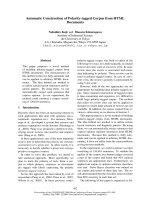
The HOLE dialog box
In Pro/ENGINEER holes are created using the HOLE dialog box. The HOLE dialog box is
displayed when you choose Insert > Hole from the menu bar or PART > Feature > Create >
Solid > Hole from the Menu Manager. You can create three types of holes using the HOLE
dialog box. The first type is a straight hole, the second is a sketched hole, and the third is a
standard hole.
Straight hole
Straight holes are the holes that have a circular cross-section having a constant diameter
throughout the depth. They start at the placement plane and terminate at the user-defined
depth or at the specified end surface. The HOLE dialog box with Straight hole radio button
selected is shown in Figure 5-1. The different options available in this dialog box are discussed
next.
Hole Dimension area
The Hole Dimension area has all the options that define the dimensions for the hole.
The options in this area are discussed next.
Diameter. The Diameter edit box is used to enter the diameter value for the hole to
be created.
Depth One. The Depth One option is used to specify the depth of the hole in one
direction. The direction for this depth is shown by a single red colored arrow that is
displayed on the plane selected for placing the hole. By default the Variable option is
selected in this drop-down list. The other options in this drop-down list are shown in
Figure 5-2. These options are similar to those discussed in the SPEC TO menu in
Chapter 3.
Depth Two. The Depth Two option is used to specify the depth of the hole in the
direction opposite to that of Depth One. This means the hole can be created on both
sides of the sketching or the placement plane. The direction for this depth is shown
by a yellow colored double arrow on the plane selected for placing the hole. By default,
the None option is selected in this drop-down list. The other options in this list are
shown in Figure 5-3.
Options Aiding Construction of Parts-I 5-3
© CADCIM T© CADCIM T
© CADCIM T© CADCIM T
© CADCIM T
echnologies, USAechnologies, USA
echnologies, USAechnologies, USA
echnologies, USA
. F. F
. F. F
. F
or engineering seror engineering ser
or engineering seror engineering ser
or engineering ser
vices, contact , contact
vices, contact , contact
vices, contact
Figure 5-1 HOLE dialog box with the Straight hole option
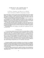
Figure 5-3 Depth Two drop-down listFigure 5-2 Depth One drop-down list
Depth Value. The Depth Value edit box is used to enter the depth value for the hole.
This edit box is displayed only when you choose the Variable option from the Depth
One drop-down list or the Depth Two drop-down list.
5-4 Pro/ENGINEER for Designers
© CADCIM T© CADCIM T
© CADCIM T© CADCIM T
© CADCIM T
echnologies, USAechnologies, USA
echnologies, USAechnologies, USA
echnologies, USA
. F. F
. F. F
. F
or online training, contact online training, contact
or online training, contact online training, contact
or online training, contact
Figure 5-5 Linear dimensioning of hole
Figure 5-6 Radial dimensioning of hole
Figure 5-4 Placement
Type drop-down list
Hole Placement area
In the Hole Placement area of the HOLE dialog box all the parameters that will define
the placement of a hole are specified. The options in this area are discussed next.
Primary Reference. The Primary Reference option is used to select a reference with
respect to which the hole will be placed. The primary reference can be a plane, a
cylinder, a cone, an axis, or a point. The primary reference selected is used to specify
the location of hole placement. When you choose the arrow button adjacent to this
option, the GET SELECT menu is displayed. You can use the Query Select option
from the GET SELECT menu to make a selection on the model.
Placement Type. The Placement Type drop-down list is
shown in Figure 5-4. The options in this drop-down list
are discussed next.
Linear. When you select this option, you are prompted
to specify the distances from two linear references.
Generally, these linear references are the edges of
the planar surface on the model, any two planar
surfaces or axes, or a combination of any of these.
Figure 5-5 shows the linear hole on a plane.
Radial. This option is used to create a hole that can be referenced to an axis.
When you select this option, you are prompted to select an axial reference and an
angular reference to place the hole. The distance from the axis is entered in the
Distance edit box and angle is entered in the Angle edit box that is displayed
when you select the axis and the plane for the angular reference. This option is
usually used to create holes on flanges. Figure 5-6 shows a radial hole on a plane.
Diameter. This option creates a diametrically placed hole. When you select this
option, you are prompted to select an axial reference and an angular reference to
place the hole. Figure 5-7 shows a diameter hole on a plane.
Options Aiding Construction of Parts-I 5-5
© CADCIM T© CADCIM T
© CADCIM T© CADCIM T
© CADCIM T
echnologies, USAechnologies, USA
echnologies, USAechnologies, USA
echnologies, USA
. F. F
. F. F
. F
or engineering seror engineering ser
or engineering seror engineering ser
or engineering ser
vices, contact , contact
vices, contact , contact
vices, contact
Figure 5-8 Coaxial holeFigure 5-7 Diameter dimensioning of hole
Coaxial. This option creates a hole coaxially. When you select this option, you
are prompted to select an axis. No dimensions are required to place a coaxial
hole. Figure 5-8 shows a coaxial hole on a plane.
Sketched hole
The Sketched option allows you to sketch the cross-section for the hole that is revolved about
a center axis. This option is used to draw custom shapes for the hole. When you choose this
radio button in the HOLE dialog box, the system opens a new window with the sketcher
environment. The cross-section for the hole is sketched using the normal sketcher options
available. While drawing the sketch, a center line must be drawn that acts as the axis of
revolution for the section of hole. The sketched holes can be a blind or a through hole
depending upon the dimensions of the section sketch.
When you complete the sketch for the hole and choose the Continue with the current section.
button, the window is closed and you are returned to the HOLE dialog box. You will be
prompted to select the placement type for the sketched hole. The placement options are the
same as discussed earlier.
Standard Hole
The holes created using the Standard Hole option are based on industry standard fastener
tables. The Standard Hole option allows you to create two types of holes, Tapped holes and
Clearance holes. In the Tapped holes, the cosmetic thread is included in the hole, whereas in
the Clearance holes, the cosmetic threads are not included.
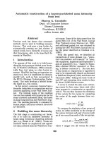
Figure 5-9 shows the HOLE dialog box with the Tapped Hole radio button and Add
Counterbore check box selected. In the Hole Dimension area of the HOLE dialog box, the
Tip: Remember that while placing any hole using the HOLE dialog box, you have to
define two steps. First is the placement plane on which the hole feature will be created
and the second is the dimensional references for all holes other than the Co-axial and
On Point hole.
5-6 Pro/ENGINEER for Designers
© CADCIM T© CADCIM T
© CADCIM T© CADCIM T
© CADCIM T
echnologies, USAechnologies, USA
echnologies, USAechnologies, USA
echnologies, USA
. F. F
. F. F
. F
or online training, contact online training, contact
or online training, contact online training, contact
or online training, contact
Figure 5-9 The HOLE dialog box with Standard Hole option
preview of the sketch for the cross-section of the counterbore hole is displayed with various
dimensions. A counterbore hole is a stepped hole and has two diameters, a larger one and a
smaller one. The larger diameter is called counter diameter and the smaller diameter is called
drill diameter. In the preview of the sketch, the dimensions can be edited as required.
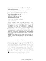
Figure 5-10 shows the HOLE dialog box with the Clearance radio button and Add
Countersink check box selected. In the Hole Dimension area of the HOLE dialog box, the
preview of the sketch for the cross-section of the countersink hole is displayed with various
dimensions. A countersink hole has two diameters but the transition between the bigger
diameter and the smaller diameter is in the form of a tapered cone. In the preview of the
sketch, the dimensions can be edited as required.
Preview the Hole
The Preview feature geometry button is used to preview the hole created using
Options Aiding Construction of Parts-I 5-7
© CADCIM T© CADCIM T
© CADCIM T© CADCIM T
© CADCIM T
echnologies, USAechnologies, USA
echnologies, USAechnologies, USA
echnologies, USA
. F. F
. F. F
. F
or engineering seror engineering ser
or engineering seror engineering ser
or engineering ser
vices, contact , contact
vices, contact , contact
vices, contact
Figure 5-10 The HOLE dialog box with Standard Hole option
the HOLE dialog box before confirming its creation. This button is provide at the bottom of
the HOLE dialog box. Changes and modifications in the hole parameters can be made easily
once the hole is previewed. While previewing the hole, it is recommended to use the Model
Display toolbar to change the model display.
Repeating the Hole feature
The Build feature and repeat the same feature type creation. button is used to
confirm the hole feature creation and at the same time invoke the HOLE dialog
box again to create the next hole feature. This button is generally used when
you want to create more than one hole.
Note
The holes created using the HOLE dialog box are parametric in nature and hence can be
modified at anytime using the Model Tree. The method of modification using the Model Tree is
discussed later in this chapter.
5-8 Pro/ENGINEER for Designers
© CADCIM T© CADCIM T
© CADCIM T© CADCIM T
© CADCIM T
echnologies, USAechnologies, USA
echnologies, USAechnologies, USA
echnologies, USA
. F. F
. F. F
. F
or online training, contact online training, contact
or online training, contact online training, contact
or online training, contact
Figure 5-11 ROUND
TYPE menu
Figure 5-12 RND
SET ATTR menu
ROUNDS
The Round option in the Insert menu creates a fillet or smooth rounded
transition with either a circular or a conic profile between two adjacent
surfaces. This option can be invoked from the menu bar or from the
Menu Manager. The Round option can either add or remove material,
depending on the edge references selected. There are two types of
rounds, as shown in Figure 5-11, that can be created in Pro/ENGINEER.
The ROUND TYPE menu is displayed when you choose PART >
Feature > Create > Solid > Round from the Menu Manager or Insert
> Round from the menu bar.
Simple and Advanced Rounds
In Pro/ENGINEER, you can create two different types of rounds, simple and advanced. The
type of round you create depends on your need to customize the default round geometry
created. Both types of rounds need placement references.
After you specify placement references and the radius of the round, the system generates the
default round geometry by using some default attributes like the round shape, cross section,
and so on. You can preview the round using the Preview button from the ROUND dialog box.
A simple round uses a circular cross-section and rolling shapes.
An advanced round allows you to define round sets between which the
default transitions are created. These transitions can be modified later.
The options that are available to define the type of round and that help
to select the geometric references are shown in Figure 5-12. These options
are available in the RND SET ATTR (ROUND SET ATTRIBUTE)
menu that is displayed when you choose Simple from the ROUND
TYPE menu.
The options used to specify the type of round are discussed next.
Constant
The Constant option with the Edge Chain option is selected by default
when the RND SET ATTR menu is displayed. This option creates a
round by assigning the same radius value to every selected edge or
surface. Figure 5-13 shows the constant round. This option is used when
the selected edge require the same radii throughout.
Variable
The Variable option allows you to specify different radii at the end points of the selected edge
Tip: Rounds and chamfers are used in components to reduce the stress concentration
at the sharp corners. Hence, they reduce the chances of failure of a
component under a specified load condition
Options Aiding Construction of Parts-I 5-9
© CADCIM T© CADCIM T
© CADCIM T© CADCIM T
© CADCIM T
echnologies, USAechnologies, USA
echnologies, USAechnologies, USA
echnologies, USA
. F. F
. F. F
. F
or engineering seror engineering ser
or engineering seror engineering ser
or engineering ser
vices, contact , contact
vices, contact , contact
vices, contact
Figure 5-15 Full round using Edge Pair option
Figure 5-14 Variable radius round using Surf-
Surf option
Figure 5-13 Constant radius round using Edge
Chain option
or optionally at additional points along the selected edge. Additional points can be defined
along the edge. But for this purpose, these points should be datum points and should lie
along the selected edge. Figure 5-14 shows the variable round. This option is used when the
selected edge(s) require variation in radius along it.
Full Round
The Full Round option creates a complete
round between two selected edges or two
planar or non planar surfaces. Figure 5-15
shows the round created using the Full
Round option between the edge on the upper
and the lower face of the base of the model.
The following options are used to specify the
references. These options are available in the
RND SET ATTR menu.
Thru Curve
When you use the Thru Curve option the
round is created between two surfaces in
which one of the tangent edges follows a
curve.
Edge Chain
The Edge Chain option allows you to select a chain of edges using the options from the
CHAIN menu. This option is not available when you choose the Full Round type of round.
The CHAIN menu is displayed when you choose Done from the RND SET ATTR menu. You
can use the Query Select option from the GET SELECT menu to select edge(s). The round is
created on the selected edge that joins the two surfaces. Figure 5-13 shows the round created
using this option.
5-10 Pro/ENGINEER for Designers
© CADCIM T© CADCIM T
© CADCIM T© CADCIM T
© CADCIM T
echnologies, USAechnologies, USA
echnologies, USAechnologies, USA
echnologies, USA
. F. F
. F. F
. F
or online training, contact online training, contact
or online training, contact online training, contact
or online training, contact
CHAIN menu
The CHAIN menu is displayed when you choose Edge
Chain option from the RND SET ATTR menu and choose
Done. The CHAIN menu is displayed with the GET
SELECT menu as shown in Figure 5-16. The options
available in the CHAIN menu are discussed next.
One by One. The One by One option allows you to
select individual edges or curves, one at a time. The
Query Select option can be used to select the edges or
curves. When you select the edges or curves, they are
highlighted in blue one by one. After selecting all the
edges or curves confirm the selection by choosing Done
Sel from the GET SELECT submenu. All the selected
edges will change to cyan.
Tangent Chain. The Tangent Chain option is used to
select all the edges tangent to the selected edge.
Instead of using the One by One option, you can use
this option to select all the edges that are tangent to
the selected edge.
Surf Chain. The Surf Chain option allows you to select the
chain of edges of the selected surface. When you select a
surface on the model, the CHAIN OPT submenu is displayed
as shown in Figure 5-17. This menu has two options.
Select All. When you choose this option, the system
selects all the edges of the selected surface.
From-To. When you choose this option, the system
displays green colored points called vertices on the selected
surface edges. The system prompts you to select from and
to points to specify a loop. The selected loop is highlighted
in blue.
To select the loop for making the round, the CHOOSE
submenu is displayed as shown in Figure 5-18.
Intent Chain. The Intent Chain option is used to select all the tangent or non-tangent
edges that form a chain with the selected edge.
Unselect. The Unselect option is used to unselect the selections made using the
other options from the CHAIN menu.
Surf-Surf
The Surf-Surf option is used to create a fillet between two planar or non-planar surfaces by
Figure 5-18 CHOOSE
menu
Figure 5-17 CHAIN
OPT submenu
Figure 5-16 CHAIN menu
with the GET SELECT menu
Options Aiding Construction of Parts-I 5-11
© CADCIM T© CADCIM T
© CADCIM T© CADCIM T
© CADCIM T
echnologies, USAechnologies, USA
echnologies, USAechnologies, USA
echnologies, USA
. F. F
. F. F
. F
or engineering seror engineering ser
or engineering seror engineering ser
or engineering ser
vices, contact , contact
vices, contact , contact
vices, contact
Figure 5-19 Different types of chamfers
defining the radius of the fillet. When you select the Surf-Surf option and choose Done from
the RND SET ATTR menu, you are prompted to select the first surface for round or fillet.
After selecting the first surface you are prompted to select the second surface. Specify the
radius of fillet in the Message Input Window and the round is created between the two
selected surfaces and is tangent to the selected surfaces. Figure 5-14 shows the round created
using this option.
Edge-Surf
The Edge-Surf option creates a round by defining a chain of edges and surface. The round
created is tangent to the selected surface only and not to the edges. This option is not
available when you choose the Thru Curve type of round.
Edge Pair
The Edge Pair option is available only when you choose to create the Full Round type of
round. This option is used when you have to create a semicircular fillet between two surfaces
by selecting its edges. Figure 5-15 shows the round created using this option.
Note
You can create advanced rounds using the different options in the same way as simple rounds are
created. For advanced rounds you need to define the round sets.
CHAMFERS
Chamfers are used to bevel the selected edges
and corners with the help of some specified
parameters. The Chamfer option can be
invoked from the menu bar or from the Menu
Manager. Pro/ENGINEER creates two type
of chamfers. The first is the Edge chamfer
and the second is the Corner chamfer.
When you choose Insert > Chamfer from
the menu bar or PART > Feature > Create
> Solid > Chamfer from the Menu Manager,
you have two options. These options are Edge
and Corner. Figure 5-19 shows the two types
of chamfers.
Edge Chamfer
An Edge chamfer creates a beveled surface along the selected edge. When you choose the
Edge option, the SCHEME menu is displayed as shown in Figure 5-20. The options in this
menu are discussed next.
45 x d
The 45 x d option creates a chamfer at the intersection of two perpendicular surfaces. The
chamfer created is at an angle of 45-degree from both the surfaces and at a distance d from the
5-12 Pro/ENGINEER for Designers
© CADCIM T© CADCIM T
© CADCIM T© CADCIM T
© CADCIM T
echnologies, USAechnologies, USA
echnologies, USAechnologies, USA
echnologies, USA
. F. F
. F. F
. F
or online training, contact online training, contact
or online training, contact online training, contact
or online training, contact
Figure 5-21 The
PICK/ENTER menu
edge along each surface. Once the chamfer is created, the distance d
can be modified.
d x d
The d x d option creates a chamfer such that the distance of the
selected edge is equal from both the faces.
d1 x d2
The d1 x d2 option creates a chamfer at two user-defined distances
from the selected edge. When you invoke this option, you will be
prompted to select the reference surface. This is the surface along which
the first distance will be measured from the selected edge.
Ang x d
The Ang x d option creates a chamfer at a user-defined distance from the selected edge and at
a user-defined angle measured from a specified surface.
Corner Chamfer
A Corner chamfer creates a beveled surface at the intersection of three
edges. When you choose this option, the GET SELECT menu is displayed
and you are prompted to select a corner that has to be chamfered. When
you select the corner, the PICK/ENTER menu is displayed as shown in
Figure 5-21. Use the options in the PICK/ENTER menu to specify the
chamfer distance. The options in this menu are discussed next.
Pick Point
The Pick Point option is used to select a point on the highlighted edge. The point selected on
the edge denotes the chamfer distance from the corner. After you have specified the point on
the highlighted edge, the next edge will be highlighted.
Enter-input
When you use the Enter-input option, the Message Input Window is displayed and you are
prompted to enter the chamfer distance for the highlighted edge.
After you enter the distance value for all the three edges the corner chamfer is created.
RIBS
Ribs are defined as thin wall-like structures used to bind the joints together so that they do not
fail under an increased load. In Pro/ENGINEER, the section for the rib is sketched as an open
section and is always extruded equally in both the directions of the sketch plane. The procedure
of creating a rib is similar to that of creating a protrusion.
In Pro/ENGINEER, you can create two types of ribs: Rotational ribs and Straight ribs.
Rotational ribs are constructed on cylindrical parts and straight ribs are created on planar
faces. There are no separate options available for the creation of these ribs in Pro/ENGINEER.
Figure 5-20 The
SCHEME menu
Options Aiding Construction of Parts-I 5-13
© CADCIM T© CADCIM T
© CADCIM T© CADCIM T
© CADCIM T
echnologies, USAechnologies, USA
echnologies, USAechnologies, USA
echnologies, USA
. F. F
. F. F
. F
or engineering seror engineering ser
or engineering seror engineering ser
or engineering ser
vices, contact , contact
vices, contact , contact
vices, contact
The creation of these of ribs depends on the geometry of the base feature. Figure 5-22 shows
a rotational rib and Figure 5-23 shows a straight rib.
Note
Since the ribs are always extruded on both sides of the sketching plane, therefore, while creating
a rib you must always select an appropriate sketching plane such that it lies at the center of
rib creation.
EDITING THE FEATURES OF A MODEL
Editing is one of the most important aspects of product designing. Most of the designs require
editing either during their creation or after they are created. As mentioned earlier,
Pro/ENGINEER is a parametric solid modeling tool. Hence, the features that together constitute
a model can be individually edited. For example, Figure 5-24 shows a cylindrical part that has
six counterbore holes created at some bolt circle diameter (BCD).
Now, in case you have to edit the features such that the six holes are to be converted into eight
holes and the counterbore holes are to be converted into countersink holes, as shown in
Figure 5-25, all you need to do is to use two operations. The first operation will convert the six
holes into eight holes by using the Modify option in the PART menu. The second operation
will open the HOLE dialog box and convert the counterbore holes into countersink holes.
Similarly, you can also edit the datums and the features referenced to these datums. Since
there exists a parent-child relationship between the two, therefore, the child feature is also
modified when the parent feature is modified. For example, if you have created a feature using
a datum plane that is at some offset distance, the feature will be automatically repositioned
when the offset value of the datum plane is changed. The following methods explain how to
edit the features in Pro/ENGINEER.
Redefining Features
Redefining features allows you to make changes in the parameters that were used to create a
feature. You can also modify the sketches of the sketched features by redefining it. A feature is
Figure 5-23 Straight Rib featureFigure 5-22 Rotational Rib feature
5-14 Pro/ENGINEER for Designers
© CADCIM T© CADCIM T
© CADCIM T© CADCIM T
© CADCIM T
echnologies, USAechnologies, USA
echnologies, USAechnologies, USA
echnologies, USA
. F. F
. F. F
. F
or online training, contact online training, contact
or online training, contact online training, contact
or online training, contact
redefined only when it is completed. To invoke the Redefine option there are three methods
available in Pro/ENGINEER. These methods are listed next.
• Choose PART > Feature > Redefine from the Menu Manager. You will be prompted to
select the feature that has to be redefined from the graphics screen. Select the feature
using the left mouse button. The selected feature is highlighted in red.
• You can select the feature that has to be redefined from the graphics screen. The selected
feature is highlighted in red. Now, hold down the right mouse button. A shortcut menu is
displayed; choose Redefine from this menu.
• You can also use the Model Tree to redefine a feature. Select the feature that has to be
redefined from the Model Tree. The selected feature is highlighted in red on the graphics
screen. Now, right-click on the feature listed in the Model Tree. A shortcut menu is
displayed; choose Redefine from this menu.
There are two types of features that are created in Pro/ENGINEER. Features that have elements
and features that do not have elements. Features that do not have elements are ribs, etc. When
you redefine a feature that does not have elements, then the REDEFINE menu is displayed.
And when you redefine a feature that has elements, then the Feature Creation dialog box is
displayed.
Procedure to redefine a feature with elements
Choose PART > Feature > Redefine and select a feature that has elements. The Feature
Creation dialog box is displayed with all the elements and their definitions. You can select any
element and choose Define from this dialog box. The menu corresponding to the element
will be displayed and now you can redefine that element. The Feature Creation dialog box is
discussed in detail in Chapter 3.
Procedure to redefine a feature without elements
Choose PART > Feature > Redefine and select a feature that do not have elements, for
Figure 5-25 Eight countersink holesFigure 5-24 Six counterbore holes
Options Aiding Construction of Parts-I 5-15
© CADCIM T© CADCIM T
© CADCIM T© CADCIM T
© CADCIM T
echnologies, USAechnologies, USA
echnologies, USAechnologies, USA
echnologies, USA
. F. F
. F. F
. F
or engineering seror engineering ser
or engineering seror engineering ser
or engineering ser
vices, contact , contact
vices, contact , contact
vices, contact
Figure 5-26 SELECT
FEAT submenu
Figure 5-27 Model with pattern
example, a rib. The REDEFINE menu is displayed. This menu has check boxes in front of
each parameter. Select the parameters that have to be redefined and choose Done. The menu
corresponding to the selected parameter is displayed and now you can redefine that parameter.
Reordering
Reordering the features is defined as the process of changing the order
of features in a model. Sometimes, after creating a model it may be
required to change the order in which the features of the model were
created. A feature can be placed before or after another feature. For
this purpose either the Model Tree or the Menu Manager is used.
If you use the Model Tree, you just have to drag and drop the feature
you want to reorder below or above the destination feature.
If you use the Menu Manager, the Reorder option is available in PA RT
> Feature > Reorder. When you choose the Reorder option from the
FEAT menu, the SELECT FEAT submenu is displayed along with the
GET SELECT submenu as shown in Figure 5-26 and you are prompted
to select the features that you want to reorder. Select the feature to be
reordered either from the Model Tree or from the graphics screen and
then choose Done Sel from the GET SELECT submenu or use the
middle mouse button to confirm the selection. In the Message area,
the system will display the possible positions where the selected
feature can be inserted. The features are numbered according to their
occurrence in the Model Tree.
The example that is discussed here will
explain why and when the need for
reordering of features in a model arises.
Consider the model shown in Figure 5-27. It
consists of a rectangular pattern of nine
columns and four rows. Now, a shell feature
is created on this model that removes the top
and the front face as shown in Figure 5-28.
Figure 5-28 shows that the material equal to
the wall thickness of the shell feature is added
around the hole features. This was not
desired, and here the need for reordering the
feature arises. You will reorder the features
such that the shell feature is inserted before
the hole feature and its pattern. When you reorder the features, all the features will be auto-
matically adjusted in the new order as shown in Figure 5-29.
Rerouting
The Reroute option available in the FEAT menu is used to modify the references of a feature
5-16 Pro/ENGINEER for Designers
© CADCIM T© CADCIM T
© CADCIM T© CADCIM T
© CADCIM T
echnologies, USAechnologies, USA
echnologies, USAechnologies, USA
echnologies, USA
. F. F
. F. F
. F
or online training, contact online training, contact
or online training, contact online training, contact
or online training, contact
and in turn break the parent child relation that exists between the selected feature and the
other features.
Suppressing
When you do not want a feature to be displayed on the graphics screen or to show up in the
drawing views of a model then that feature can be suppressed. Once the feature is suppressed,
it will neither be displayed in the drawing views nor on the graphics screen. Note that the
feature is not deleted, only its visibility is turned off. You can anytime resume the feature by
unsuppressing it using the Model Tree or using the Menu Manager. As soon as you unsuppress
the feature, it will be displayed on the graphics screen as well as in the drawing views. When a
model has many features then the suppressing of features decreases the regeneration time of
the new feature created. To suppress a feature right-click on it in the Model Tree or select it on
the graphics screen using the left mouse button and press and hold down the right mouse
button to display the shortcut menu. Choose Suppress from the shortcut menu to suppress
the selected feature. You can also suppress a feature using the Menu Manager.
Note
If the feature that is suppressed has some child features then they will also be suppressed. When
you select such a feature, the system prompts you to confirm the suppression of the highlighted
features on the graphics screen.
Deleting a feature
The feature that is not required can be deleted from the model. Right-click on the feature in
the Model Tree or select it on the graphics screen and press and hold down the right mouse
button to display the shortcut menu. From this menu choose the Delete option. The feature to
be deleted is highlighted in red. If the feature to be deleted has some child features, they will
also be highlighted. The system confirms before deleting the selected feature. If you confirm
the deletion, the feature along with its child features will be deleted.
Figure 5-28 Model after creating the shell
feature
Figure 5-29 Model after reordering the features
Options Aiding Construction of Parts-I 5-17
© CADCIM T© CADCIM T
© CADCIM T© CADCIM T
© CADCIM T
echnologies, USAechnologies, USA
echnologies, USAechnologies, USA
echnologies, USA
. F. F
. F. F
. F
or engineering seror engineering ser
or engineering seror engineering ser
or engineering ser
vices, contact , contact
vices, contact , contact
vices, contact
Modifying a feature
Once a feature is created, you can still modify the feature by modifying its dimensions. This
editing operation reflects the parametric nature of Pro/ENGINEER. The Modify option is
available in the PART menu. When you choose the Modify option, the system prompts you to
select the feature that is to be modified. Select the feature on the graphics screen using the left
mouse button. The selected feature is highlighted in red and the dimensions appear on the
feature. These dimensions are the same that were defined while sketching or creating the
feature. In some cases, for example, rounds, holes, and so on, the dimensions of these features
were defined as parameters. Hence, these dimensions are also displayed when you select them
to modify. To modify the dimensions, select the dimension from the graphics screen. When
the Message Input Window appears, enter the required value for the selected dimension and
press ENTER. Once you modify a dimension, you also need to regenerate the feature. The
Regenerate option is also available in the PART menu.
If you want to modify a pattern, it is recommended that you select the instance other than the
original one. This is because if you select the original feature, the incremental dimensions are
not displayed and so you cannot modify the incremental values of the pattern.
Dynamic Modification of a Feature
With this release of Pro/ENGINEER, you are allowed to dynamically modify extruded, revolved,
rounded features that have a variable value assigned. For example, the depth of extrusion in
case of extruded features, the angle of revolution in case of revolved features, and the radius
in case of rounds. The child features, if any, will also be modified when the parent feature is
modified.
To modify an extruded feature dynamically, select the feature from the Model Tree or from
the graphics screen and hold down the right mouse button when the feature is highlighted in
red. A shortcut menu is displayed. Choose the Dynamic Modify option from this menu. A
yellow colored small box is displayed with an axis. Select the small box by holding down the
left mouse button. The arrow cursor changes to a two-sided arrow and the yellow color of the
box is changed to red. The two-sided arrow is displayed showing that the modification can be
made on either side. Holding down the left mouse button, drag the mouse to the side on
which the depth has to be modified. As you drag the mouse, the depth of extrusion is modified
dynamically. You will notice that the system displays the preview of the feature before actually
modifying it. After modifying the extrusion dynamically, release the left mouse button. To
confirm the modification, left-click on the screen or press the middle mouse button. The
feature will regenerate and is modified. Figure 5-30 shows the preview of the feature with the
yellow box and the axis, and Figure 5-31 shows the feature after regeneration.
Tip: By default, the suppressed features are not displayed in the Model Tree. To
display the suppressed features, choose View > Model Tree Setup > Item Display
from the menu bar. The Model Tree Items dialog box is displayed. Select the
Suppressed Objects check box and choose OK from the Model Tree Items dialog
box. The suppressed features will now be displayed in the Model Tree.
The suppressed features can also be deleted by using the Model Tree.
5-18 Pro/ENGINEER for Designers
© CADCIM T© CADCIM T
© CADCIM T© CADCIM T
© CADCIM T
echnologies, USAechnologies, USA
echnologies, USAechnologies, USA
echnologies, USA
. F. F
. F. F
. F
or online training, contact online training, contact
or online training, contact online training, contact
or online training, contact
Using Selections dialog box
The Selections dialog box is used when there are many features in a
model and the feature you want to select is cluttered by other adjacent
features. To display this dialog box select any feature in that portion
of the model using the left mouse button and then right-click.
Remember that instead of right-clicking if you hold the right mouse
button down, the shortcut menu is displayed not the Selections dialog
box. Figure 5-32 shows the Selections dialog box.
After the Selections dialog box is displayed, you can select the
feature from this dialog box and perform any editing operation on
it. The feature can be selected in this dialog box by either using the
left mouse button or using the arrow buttons available in the dialog
box. The selected feature in the dialog box is highlighted in red
color on the graphics screen. To confirm the selection, use the middle
mouse button.
The Selections dialog box is one of the methods to select a feature to edit. There are some
other methods also to select a feature of a model. You can use the Model Tree of the model.
You can also directly select the feature to be edited from the model using the left mouse button.
TUTORIALS
Create the model shown in Figure 5-33. The dimensions, the front, top, and left-side views of
the model are also shown in the figure. (Expected time: 45 min)
The following steps outline the procedure for creating this model:
a. First examine the model and then determine the number of features in it. The model is
composed of eight features, see Figure 5-33.
Figure 5-32 Selections
dialog box
Tutorial 1
Figure 5-31 Feature after modification
Figure 5-30 Dynamic modification of the feature
Options Aiding Construction of Parts-I 5-19
© CADCIM T© CADCIM T
© CADCIM T© CADCIM T
© CADCIM T
echnologies, USAechnologies, USA
echnologies, USAechnologies, USA
echnologies, USA
. F. F
. F. F
. F
or engineering seror engineering ser
or engineering seror engineering ser
or engineering ser
vices, contact , contact
vices, contact , contact
vices, contact
b. The first four features are extruded features, see Figure 5-42. First the sketch of base
feature will be created on the FRONT datum plane, see Figure 5-34, and then it will be
extruded to a depth of 10.
c. The sketch of the second feature will be created on the TOP datum plane and will be
extruded on one side of the sketching plane. The depth of extrusion is 10, see Figure 5-37.
d. The sketch of the third feature will be created on the front planar surface of the second
feature and will be extruded on one side of the sketching plane. The depth of extrusion is
10, see Figure 5-40.
e. The sketch of the cylindrical feature will be drawn on the front planar surface of the third
feature and extrusion will be on both sides of the plane. The depth of extrusion on one
side is 12 and on the other side is 13, see Figure 5-42.
f. The next feature is a hole that is coaxial to the cylindrical feature, see Figure 5-43. This
hole will be created using the HOLE dialog box.
g. The next two features that will be created are rounds. The two rounds have different radii.
Figure 5-33 Isometric shaded view, left-side, front, and top views of the model
5-20 Pro/ENGINEER for Designers
© CADCIM T© CADCIM T
© CADCIM T© CADCIM T
© CADCIM T
echnologies, USAechnologies, USA
echnologies, USAechnologies, USA
echnologies, USA
. F. F
. F. F
. F
or online training, contact online training, contact
or online training, contact online training, contact
or online training, contact
Hence, they will be created as two separate features.
h. The last feature is a rib. The sketch for this feature will be drawn on the RIGHT datum
plane, see Figure 5-46.
After understanding the procedure for creating the model, you are now ready to create it.
When Pro/ENGINEER session is started, the first task is to set the working directory. Since this
is the first tutorial of this chapter, you need to create a folder named c05, if it does not exist.
Choose the New Directory button in the Select Working Directory dialog box and create a
directory named c05 at C:\ProE.
Creating New Object File
1. Open a new part file and name it c05tut1. The three default datum planes will be displayed
on the graphics screen. The Model Tree is also displayed on the graphics screen. Exit the
Model Tree by choosing the Model Tree on/off button from the Model Display toolbar.
Creating the Base Feature
To create the sketch for the base feature, you need to first select the sketching plane for the
base feature. In this model, you need to draw the base feature on the FRONT datum plane
because direction of extrusion of this feature is perpendicular to this plane.
1. Choose Insert > Protrusion > Extrude from the menu bar. The ATTRIBUTES menu is
displayed. Choose One Side > Done from this menu.
2. Select the FRONT datum plane as the sketching plane. The DIRECTION submenu is
displayed.
3. Choose Okay from this submenu. The SKET VIEW submenu is displayed.
4. Select the Top option from this submenu and choose the TOP datum plane from the
graphics screen.
Note
Before you start sketching a section for any feature, it is recommended to turn the model display
to No Hidden and turn off the datum plane display using the Datum planes on/off button.
This is done to improve the clarity of the graphics screen while sketching.
When you are working on these tutorials, make extensive use of buttons available in the Datum
Display toolbar.
5. Once you enter the sketcher environment, create the sketch of the base feature and apply
constraints and dimensions as shown in Figure 5-34. Note that in the sketch, the bottom
line of the rectangular section coincides with the TOP datum plane.
As evident from the sketch of the base feature shown in Figure 5-34, the RIGHT datum
plane is located at a dimension of 50 from the left edge because later in the tutorial, the
rib feature will be created on this plane. The distance of 50 can be calculated from
Options Aiding Construction of Parts-I 5-21
© CADCIM T© CADCIM T
© CADCIM T© CADCIM T
© CADCIM T
echnologies, USAechnologies, USA
echnologies, USAechnologies, USA
echnologies, USA
. F. F
. F. F
. F
or engineering seror engineering ser
or engineering seror engineering ser
or engineering ser
vices, contact , contact
vices, contact , contact
vices, contact
Figure 5-33. As mentioned earlier, the sketch for a rib is by default extruded to both the
sides of the sketching plane. Therefore, when you create the sketch for the rib feature on
the RIGHT datum plane, it will be extruded on both the sides of the sketching plane.
6. After the sketch is complete, choose the Continue with the current section. button to exit
the sketcher environment.
The SPEC TO menu is displayed and you are prompted to specify the depth of extrusion.
7. The Blind option is selected by default in this menu, choose Done.
8. Enter the depth as 10 in the Message Input Window that appears and press ENTER.
Choose OK from the PROTRUSION dialog box.
9. Choose the Default option from the Saved view drop-down list.
The base feature is completed and now the second feature will be created.
Creating the Second Feature
The second feature is also an extruded feature and will be created on the TOP datum plane.
Therefore, you need to define the TOP datum plane as the sketching plane.
1. Choose Insert > Protrusion > Extrude from the menu bar. The ATTRIBUTES menu is
displayed. Choose One Side > Done from this menu.
2. Select the TOP datum plane as the sketching plane. The DIRECTION submenu is
displayed. Choose Okay from this submenu. The SKET VIEW submenu is displayed.
3. Select the Bottom option from this submenu and choose the front surface of the base
feature shown in Figure 5-35.
Figure 5-35 Front planar surface selected to
be at the bottom
Figure 5-34 Sketch with dimensions and
constraints for the base feature
5-22 Pro/ENGINEER for Designers
© CADCIM T© CADCIM T
© CADCIM T© CADCIM T
© CADCIM T
echnologies, USAechnologies, USA
echnologies, USAechnologies, USA
echnologies, USA
. F. F
. F. F
. F
or online training, contact online training, contact
or online training, contact online training, contact
or online training, contact
After entering the sketcher environment, turn the model display to No Hidden.
4. Create the sketch for the second feature and apply the constraints and dimensions as
shown in Figure 5-36.
You can use the Create an entity from an edge. button from the Sketcher Tools toolbar to
use the edge of the base feature. The edge of the base feature is required to close the
section for the second feature. Note that if you use the Create an entity from an edge.
button, the 38 dimension in Figure 5-36 will not be required. However if you do not use
the edge, you will have to draw a line to close the sketch. You will then have to align it with
the bottom edge and add the constraint and dimensions as shown in Figure 5-36.
Note
If you do not close the section loop by drawing a line or using the edge of the base feature, the
DIRECTION menu will be displayed when you exit the sketcher environment. This menu will
prompt you to specify the direction in which the material will be added. The material will be
added in the direction shown by the arrow.
5. After completing the sketch, turn the model display to Shading and choose the Continue
with the current. section button. The SPEC TO menu is displayed.
6. The Blind option is selected in this menu, choose Done. The Message Input Window is
displayed with a default value in it.
7. Enter a value of 10 in the Message Input Window and press ENTER. Choose the OK
button from the PROTRUSION dialog box. The second feature is completed and the
shaded default trimetric view is shown in Figure 5-37.
Creating the Third Feature
The sketch of the third feature will be drawn on the front planar surface of the second feature
and will be extruded to the given depth.
Figure 5-37 The default trimetric view of the
completed second feature and the base feature
Figure 5-36 Sketch with dimensions and
constraints for the second feature
Options Aiding Construction of Parts-I 5-23
© CADCIM T© CADCIM T
© CADCIM T© CADCIM T
© CADCIM T
echnologies, USAechnologies, USA
echnologies, USAechnologies, USA
echnologies, USA
. F. F
. F. F
. F
or engineering seror engineering ser
or engineering seror engineering ser
or engineering ser
vices, contact , contact
vices, contact , contact
vices, contact
1. Choose Insert > Protrusion > Extrude from the menu bar. The ATTRIBUTES menu is
displayed. Choose One Side > Done from this menu.
2. Select the planar surface of the second feature shown in Figure 5-38 as the sketching
plane. The DIRECTION submenu is displayed. Choose Okay from this menu. The SKET
VIEW submenu is displayed.
3. Select the Top option from this submenu and select the top surface of the second feature.
4. Once you enter the sketcher environment, turn the model display to No Hidden. Create
the sketch for the third feature and apply constraints and dimensions as shown in
Figure 5-39.
5. Choose the Continue with the current section. button. The SPEC TO menu is displayed.
6. The Blind option is selected in the SPEC TO menu, choose Done. The Message Input
Window is displayed with a default value in it.
7. Enter a value of 10 in the Message Input Window and press ENTER.
8. Choose the OK button from the PROTRUSION dialog box. Turn the model display to
Shading. The third feature is completed. You can use the CTRL+middle mouse button to
spin the model to view it from different directions.
Creating the Fourth Feature
The fourth feature of the model is an extruded feature and the sketch of this feature is drawn
on the front planar surface of the third feature.
1. Choose Insert > Protrusion > Extrude from the menu bar. The ATTRIBUTES menu is
displayed. Choose Both Sides > Done.
Figure 5-39 Sketch with dimensions and
constraints
Figure 5-38 Planar surface selected as the
sketching plane for the third feature
5-24 Pro/ENGINEER for Designers
© CADCIM T© CADCIM T
© CADCIM T© CADCIM T
© CADCIM T
echnologies, USAechnologies, USA
echnologies, USAechnologies, USA
echnologies, USA
. F. F
. F. F
. F
or online training, contact online training, contact
or online training, contact online training, contact
or online training, contact
2. Select the planar surface shown in Figure 5-40 as the sketching plane. The extrusion of
the cylindrical feature will be on both sides of the front planar surface. The DIRECTION
submenu is displayed.
3. Choose Okay from this submenu. The SKET VIEW menu is displayed.
4. Select the To p option from this menu and choose the top planar surface of the second
feature.
5. Once you enter the sketcher environment turn the model display to No Hidden.
6. Draw the circular section for the fourth feature as shown in Figure 5-41. Choose
the Create concentric circle. button from the Sketcher Tools toolbar to draw the
sketch for this feature. Select the arc using the left mouse button. As you drag the
mouse the cyan colored rubber band circle changes its size. As you move the mouse cursor
close to the arc, the cursor snaps to the arc. Use the left mouse button and select a point on
the arc. You will notice that the equal radius constraint is applied to the sketch. Now, use
the middle mouse button to abort this option.
Note
While drawing the sketch for any feature, it is recommended to first apply the required constraints
and then dimension the sketch.
7. After the sketch is completed, choose the Continue with the current section. button. The
SPEC FROM menu is displayed.
You will need to spin the model so that the direction of arrow on the graphics screen is
clearly visible.
8. Select the 2 Side Blind option from this menu and choose Done.
The 2 Side Blind option allows you to enter the depth of extrusion in two opposite
Figure 5-41 Sketch for the fourth feature
Figure 5-40 Planar surface
Options Aiding Construction of Parts-I 5-25
© CADCIM T© CADCIM T
© CADCIM T© CADCIM T
© CADCIM T
echnologies, USAechnologies, USA
echnologies, USAechnologies, USA
echnologies, USA
. F. F
. F. F
. F
or engineering seror engineering ser
or engineering seror engineering ser
or engineering ser
vices, contact , contact
vices, contact , contact
vices, contact
directions. This option is available only when you choose the Both Sides option from the
ATTRIBUTES menu. The Both Sides option was selected in step 1.
You are prompted to specify the depth of extrusion on the inside of the sketching plane.
9. Enter a value of 13 in the first direction shown by the red arrow and the value of 12 in the
other direction. The fourth feature is completed.
10. Choose OK from the PROTRUSION dialog box.
Creating the Hole Feature
The hole feature will be created using the HOLE dialog box. The hole will be placed coaxial
to the fourth cylindrical feature.
Note
Since the hole will be created coaxially, you will be required to select the axis of the circular
feature. You may need to turn on the axis display if it is turned off. Choose the Datum axes on/
off button from the Datum Display toolbar to turn on the datum axis display.
1. Choose Insert > Hole from the menu bar. The HOLE dialog box is displayed. In the
Hole Type area, the Straight hole radio button is selected by default.
2. In the Diameter edit box of the Hole Dimension area, enter a value of 16. The hole that
will be created is of diameter 16.
3. From the Depth One drop-down list, select the Thru All option.
The None option is selected by default in the Depth Two drop-down list. The GET SELECT
menu is displayed and you are prompted to select a primary reference.
4. Select the front surface of the cylindrical feature shown in Figure 5-42 to place the hole.
As you select the front planar surface of the cylindrical feature, the GET SELECT menu is
displayed again. You are prompted to select the first reference for the hole placement.
5. From the Placement Type drop-down list, choose the Coaxial option. You are prompted
to select the hole axis.
6. Select the axis of the cylindrical feature from the graphics screen. The hole feature is
created and you can now preview it.
7. Choose the Preview feature geometry button from the HOLE dialog box.
The hole created is highlighted in red.
8. Choose the Build feature button from the HOLE dialog box. The hole is
created and the trimetric view of the shaded model with the hole is shown in
Figure 5-43.