Bài giảng môn thực hành cảm biến
Bạn đang xem bản rút gọn của tài liệu. Xem và tải ngay bản đầy đủ của tài liệu tại đây (551.25 KB, 16 trang )
ThӵFKành cҧPELӃQ
1
75ѬӠ1*ĈҤ,+Ӑ&1+$75$1*
.+2$&Ѫ.+Ë
BӜ0Ð1&ѪĈ,ӊ17Ӱ
[\
NguyӉQ9ăQĈӏQK
BÀI GIҦ1*0Ð1+Ӑ&
THӴ&+ÀNH CҦ0%,ӂ1
/˱XKjQKQ͡LE͡
1KD7UDQJQăP
ThӵFKành cҧPELӃQ
2
1. MөFÿtFK
*L~SVLQKYLrQFiFKÿRÿҥFWKXWKұSYà hiӇQWKӏJLá trӏFӫDPӝWVӕORҥLFҧPELӃQ
thông dөQJ
2. Yêu cҫX
7KDPJLDÿҫ\ÿӫFiFEXәLKӑFOêWKX\ӃWYà thӵFKành.
3. NӝLGXQJP{QKӑF
SӱGөQJEӝWKtQJKLӋP./-ÿӇÿRÿҥFYà lұSWUình hiӇQWKӏ
-CҧPELӃQWLӋPFұQ3UR[LPLW\
-CҧPELӃQQKLӋWÿӝ7HPS37-100)
-CҧPEiӃQJyFTXD\5RWDWLRQ$QJOH
-CҧPELӃQUXQJVibration)
-CҧPELӃQhӗQJQJRҥL (Infrared)
-CҧPELӃQTXDQJ&'6
ThӵFKành cҧPELӃQ
3
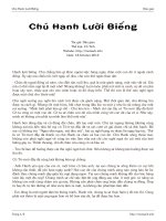
1.1. CҧPELӃQWLӋPFұQ
Inductive proximity sensors are widely used in various applications to detect
metal devices. They consist of an oscillator, trigger, and switching amplifier. If a
metal object enters the electromagnetic field of the oscillator coil, eddy currents are
induced in this coil which change the amplitude of oscillation, which causes the trigger
stage to trip and the semiconductor output stage to switch.
Circuit Explanation
When no metallic object approach to the detecting head:
Vo = High Æ Vo22 = Low Æ Q1 OFF Æ Buzzer OFF
Proximity Sensor
LED: Indicator
Detect Head
S
S
t
t
r
r
u
u
c
c
t
t
u
u
r
r
e
e
:
:
V
CC
Output
GND
Oscillator
Trigger
Switching
Amplifier
S
S
y
y
m
m
b
b
o
o
l
l
:
:
(
(
E
E
q
q
u
u
i
i
p
p
m
m
e
e
n
n
t
t
C
C
i
i
r
r
c
c
u
u
i
i
t
t
)
)
ThӵFKành cҧPELӃQ
4
When a metallic object approach to the detecting head:
Vo = LOW Æ Vo22 = High Æ Q1 ON Æ Buzzer ON
Experiment Procedure:
1. Insert proximity sensor to 3 pin module socket.
2. Power on the module
3. Use different type of object to approach to the detecting head and observe the
result. Æ
ThӵFKành cҧPELӃQ
5
1.2. CҧPELӃQQKLӋWÿӝ
PT-100 is one form of the RTD (Resistance Temperature Detector). It is made of
the platinum wire and has the resistance of 100 ohm at 00C. The resistance vs.
temperature characteristic of PT-100 can be expressed as:
RT = 100 (1+0.00392T)
If constant current I of 2.55mA flow through PT-100
VB’ = I x RT = (255+T)mV
Circuit Explanation:
Temperature (PT100) Sensor
Stainless-steel protection tube
(Platinum wired wound inside)
A
B
B’
B=B’
S
S
y
y
m
m
b
b
o
o
l
l
:
:
S
S
t
t
r
r
u
u
c
c
t
t
u
u
r
r
e
e
:
:
A
B’
Voltage Out
ThӵFKành cҧPELӃQ
6
• VR2 is used to control the constant current source to 2.25mV
• U1 is non-inverting amplifier
Æ V16= (2550+10T) mV
• U2 is differential amplifier
• U3 is voltage follower
Æ Adjust VR14 to control Vf1 (offset of U2)
• So if Vf1 = 2550mV Æ Vo27 = 100T mV Æ Conversion Ratio = 100mV / 0C
Experiment Procedure:
In this exercise, you need to prepare a thermometer (mercury) for calibration.
1. Using thermometer to record the current room temperature (T).
Æ
?
2. Connect 2 lead wires (white) to B and B’, and lead wire (red) to A.
3. Power on the module.
4. Adjust VR2 until VB’ = (255+T)mV
Æ
?
5. Adjust VR14 until Vo27 is equal to T/10 V (Calibration complete)
Æ
?
6. Put both PT-100 and the mercury thermometer inside hot water.
7. What is the value shown on the mercury thermometer?
Æ
?
8. What is the output voltage of Vo27?
Æ
?
9. Put both PT-100 and the mercury thermometer inside cold water.
ThӵFKành cҧPELӃQ
7
10.What is the value shown on the mercury thermometer?
Æ
?
11.What is the output voltage of Vo27?
Æ
?
12.What’s the difference between AD590 and PT100 temperature sensor?
Æ
?
ThӵFKành cҧPELӃQ
8
1.3. CҧPELӃQJyFTXD\
Sometimes called potentiometers, voltage dividers or variable resistors, the
precision potentiometric position transducers are widely used in measuring linear
distance, angles or rotations in production equipment. It is a three terminal resistor
where the position of the sliding connection is user adjustable via a knob. The sensor
used in this experiment is a multi-turn potentiometer (10 turns) with an attached reel of
wire turning against a spring.
Circuit Explanation:
Rotation Angle Sensor
S
S
t
t
r
r
u
u
c
c
t
t
u
u
r
r
e
e
:
:
Knob
Plastic Housing
CW
CCW
Output
(sliding connection)
Excitation
Voltage
Vout
S
S
y
y
m
m
b
b
o
o
l
l
:
:
ThӵFKành cҧPELӃQ
9
• U1 (Buffer Amplifier) provides a precision reference voltage at Vf1.
• U2 (Buffer Amplifier) transfers the voltage from U2pin3 to U2pin6.
• U4 (Buffer Amplifier) provides fix voltage (adjusted by VR7) at U4pin6 to
control the current flow through feedback loop to obtain a stable output at
Vo31.
Experiment Procedure:
1. Power on the module
2. Adjust variable resistor VR7 to center for initial position.
3. Rotate the potentiometer from most CCW to most CW position. How many
turns is built in the potentiometer?
Æ
?
4. How many degrees you have rotate in step 2?
Æ
?
5. Fix the potentiometer at 36000 Adjust the variable resistor VR2 until Vo31 is
equal to 3.600V.
6. Rotate the potentiometer in CCW direction for 5 turns. Adjust the variable
resistor VR7 until Vo31 is equal to 1.800V.
7. Measure and record the output voltage Vo31 for each following turn values.
1/2/3/4/5/6/7/8/9/10 turns
Æ
?
ThӵFKành cҧPELӃQ
10
1.4. CҧPELӃQUXQJ
The vibration switch is normally open with vibration springs. When a vibration
occurred, the switch changes to close state and the switch turns ON.
Circuit Explanation:
Vibration Switch
Contact:
to spring
Contact
to metal
Housing
S
S
y
y
m
m
b
b
o
o
l
l
:
:
S
S
t
t
r
r
u
u
c
c
t
t
u
u
r
r
e
e
:
:
ThӵFKành cҧPELӃQ
11
When vibration switch is OFF :
555 Timer (U2) OFF Æ no output at Vo10 Æ Buzzer OFF
When vibration switch is ON :
555 Timer (U2) ON Æ pulse output at Vo10 Æ Buzzer ON
Experiment Procedure:
1. Power on the module.
2. What is the status of the buzzer?
3. Knock the sensor from side, what is the status of the buzzer?
4. Knock the sensor from top, what is the status of the buzzer?
ThӵFKành cҧPELӃQ
12
1.5. CҧPELӃQhӗQJQJRҥL
Infrared emits infrared radiation which is focused by a plastic lens into a narrow
beam. The emitting beam of an IR LED is generally proportional to the magnitude of
the forward current (forward biased). The beam is modulated i.e. switched on and off,
to encode the data. The receiver uses a silicon photodiode to convert the infrared
radiation to an electric current for further processing.
Circuit Explanation:
Transmitter
(Infrared Emitting Diode)
Receiver
(Photodiode)
Anode
Cathode
Transmitter
Receiver
Vout_U2
Vout_U3
Infrared Sensor
ThӵFKành cҧPELӃQ
13
U2: Inverting amplifier, Gain = ~1000
U3: differential amplifier, Gain = ~ 22
U4: Comparator, If V+ > V- Æ output = 12V || If V->V+ Æ output = -12V
Use VR2 to adjusted the output frequency f of the 555 Timer Æ Q1
switches ON and OFF Æ Infrared TX emits ON and OFF Æ If no object blocks
between TX and RX Æ Infrared RX receives ON and OFF Æ weak pulse signal
input to U2 Æ strong pulse signal Æ Vpp = 12V, frequency = f) output at
Vout_U2 Æ At resonant frequency Æ VLc obtain maximum Vpp Æ signal
amplify again though U3 Æ CR1, C5, R13 converts the AC signal into DC
signal at U4 pin3 Æ If U4 pin3 > U4 pin2 Æ Vo17 outputs high potential
Experiment Procedure:
1. Power on the module
2. Use oscilloscope to observe the voltage at VLC and adjust the variable
resistor VR2 until Vout_U2 obtain the maximum peak-to-peak voltage.
3. Adjust VR3 until U3 pin3 is 0.3V lower than VLC
Æ
4. Record the voltage at U4 pin2 and U4 pin3 Æ
5. Block an object between the sensor, what is the voltage at U4 pin3? Æ
6. What is the value of Vo17 when nothing block the sensor? Æ
7. What is the value of Vo17 when the sensor is blocked by an object? Æ
8. What is the current frequency of the 555 Timer output? Æ
ThӵFKành cҧPELӃQ
14
1.6. CҧPELӃQTXDQJ
CaDmium Sulphide (CDS) cells, sometimes called photoresistors or
photoconductive cells, rely on the material's ability to vary its resistance according to
the amount of light striking the cell. The more light that strikes the cell, the lower the
resistance.
Circuit Explanation:
Infrared Sensor
Lead
Wires
CaDmium Sulphide
(Orange part)
S
S
t
t
r
r
u
u
c
c
t
t
u
u
r
r
e
e
:
:
S
S
y
y
m
m
b
b
o
o
l
l
:
:
ThӵFKành cҧPELӃQ
15
When light strikes the CDS:
Sensor resistance Æ Vin Æ Q1 (NPN) ON Æ Q2 (PNP) ON Æ Vo23 High
Æ
LED1 ON
When no light strikes the CDS:
Sensor resistance Æ Vin Æ Q1 (NPN) OFF Æ Q2 (PNP) OFF Æ Vo23 LOW
Æ LED1 OFF
Experiment Procedure:
1. Power on the module
2. Block the CDS and adjust variable resistor R1 make the LED1 just from the
bright to dark.
3. What is the status of the LED1 when the light strikes the CDS? And what is the
voltage at Vin? Æ
4. What is the status of the LED1 when the CDS is blocked? And what is the
voltage at Vin? Æ
5. Use oscilloscope to observe the voltage at Vin, what is the response time when
block and unblock the CDS? Æ
ThӵFKành cҧPELӃQ
16
B
B
l
l
o
o
c
c
k
k
s
s
t
t
o
o
b
b
e
e
d
d
e
e
m
m
o
o
n
n
s
s
t
t
r
r
a
a
t
t
e
e
d
d
:
:
Single Chip
Out Control 2
Out Control 3
Status Display
EPROM
Thumbwheel Switch
DC Power
+5V, GND
Select / Chip
Potentiometer
A/D Converter