construction databook construction materials and equipment second edition pdf
Bạn đang xem bản rút gọn của tài liệu. Xem và tải ngay bản đầy đủ của tài liệu tại đây (17.93 MB, 689 trang )
www.EngineeringEBooksPdf.com
Construction
Databook
www.EngineeringEBooksPdf.com
About the Author
Sidney M. Levy is an independent construction industry consultant with more than 40 years of
experience in the profession. He is the author of numerous books on construction methods and operations, including Design-Build Project Delivery, Construction Superintendent’s Operations
Manual, and Project Management in Construction for which he was awarded the British Chartered
Institute of Building Silver Medal in the category of Managing Construction.
www.EngineeringEBooksPdf.com
Construction
Databook
Construction Materials and Equipment
Sidney M. Levy
Second Edition
New York Chicago San Francisco
Lisbon London Madrid Mexico City
Milan New Delhi San Juan
Seoul Singapore Sydney Toronto
www.EngineeringEBooksPdf.com
Copyright © 2010,1999 by The McGraw-Hill Companies, Inc. All rights reserved. Except as permitted under the United States Copyright Act of 1976,
no part of this publication may be reproduced or distributed in any form or by any means, or stored in a database or retrieval system, without the prior
written permission of the publisher.
ISBN: 978-0-07-161358-3
MHID: 0-07-161358-7
The material in this eBook also appears in the print version of this title: ISBN: 978-0-07-161357-6, MHID: 0-07-161357-9.
All trademarks are trademarks of their respective owners. Rather than put a trademark symbol after every occurrence of a trademarked name, we use
names in an editorial fashion only, and to the benefit of the trademark owner, with no intention of infringement of the trademark. Where such
designations appear in this book, they have been printed with initial caps.
McGraw-Hill eBooks are available at special quantity discounts to use as premiums and sales promotions, or for use in corporate training programs.
To contact a representative please e-mail us at
Information contained in this work has been obtained by The McGraw-Hill Companies, Inc. (“McGraw-Hill”) from sources believed to be reliable.
However, neither McGraw-Hill nor its authors guarantee the accuracy or completeness of any information published herein, and neither McGraw-Hill
nor its authors shall be responsible for any errors, omissions, or damages arising out of use of this information. This work is published with the
understanding that McGraw-Hill and its authors are supplying information but are not attempting to render engineering or other professional services.
If such services are required, the assistance of an appropriate professional should be sought.
TERMS OF USE
This is a copyrighted work and The McGraw-Hill Companies, Inc. (“McGraw-Hill”) and its licensors reserve all rights in and to the work. Use of this
work is subject to these terms. Except as permitted under the Copyright Act of 1976 and the right to store and retrieve one copy of the work, you may
not decompile, disassemble, reverse engineer, reproduce, modify, create derivative works based upon, transmit, distribute, disseminate, sell, publish or
sublicense the work or any part of it without McGraw-Hill’s prior consent. You may use the work for your own noncommercial and personal use; any
other use of the work is strictly prohibited. Your right to use the work may be terminated if you fail to comply with these terms.
THE WORK IS PROVIDED “AS IS.” McGRAW-HILL AND ITS LICENSORS MAKE NO GUARANTEES OR WARRANTIES AS TO THE
ACCURACY, ADEQUACY OR COMPLETENESS OF OR RESULTS TO BE OBTAINED FROM USING THE WORK, INCLUDING ANY INFORMATION THAT CAN BE ACCESSED THROUGH THE WORK VIA HYPERLINK OR OTHERWISE, AND EXPRESSLY DISCLAIM ANY WARRANTY, EXPRESS OR IMPLIED, INCLUDING BUT NOT LIMITED TO IMPLIED WARRANTIES OF MERCHANTABILITY OR FITNESS FOR
A PARTICULAR PURPOSE. McGraw-Hill and its licensors do not warrant or guarantee that the functions contained in the work will meet your
requirements or that its operation will be uninterrupted or error free. Neither McGraw-Hill nor its licensors shall be liable to you or anyone else for any
inaccuracy, error or omission, regardless of cause, in the work or for any damages resulting therefrom. McGraw-Hill has no responsibility for the
content of any information accessed through the work. Under no circumstances shall McGraw-Hill and/or its licensors be liable for any indirect,
incidental, special, punitive, consequential or similar damages that result from the use of or inability to use the work, even if any of them has been
advised of the possibility of such damages. This limitation of liability shall apply to any claim or cause whatsoever whether such claim or cause
arises in contract, tort or otherwise.
www.EngineeringEBooksPdf.com
Contents
vii
Introduction
Section
Section
Section
Section
Section
Section
Section
Section
Section
Section
Section
01:
02:
03:
04:
05:
06:
07:
08:
09:
10:
11:
Soils, Site Utilities, Sitework Equipment
Substructures
Building Envelope
Carpentry, Framing, Drywall, Engineered Wood Products
Fireproofing and Soundproofing
Interior Finishes—Millwork, Laminates, Paint, and
Wall Coverings
Doors and Windows
Plumbing
Mechanical Systems and Equipment
Electrical
Useful Tables, Charts, and Formulas
1
83
139
207
291
337
389
457
537
591
639
663
Index
v
www.EngineeringEBooksPdf.com
This page intentionally left blank
www.EngineeringEBooksPdf.com
Introduction
The Construction DataBook, Second Edition, provides the project manager, construction superintendent, design consultants, facility managers and owners with a one-source guide for the most commonly encountered construction materials and equipment.
Composed of eleven sections ranging, in topics, from excavation and sitework to mechanical and
electrical components, the book also includes a handy set of useful tables and formulas. Quick and
easy access to informative data on these materials and systems is afforded.
Much of this material has been gleaned from manufacturers and suppliers data but a great deal of
these specifications and installation procedures are generic in nature.
The Construction DataBook, Second Edition includes several HVAC, plumbing and electrical
and alternative energy schematics that explain complex systems in easy-to-understand terms.
Installation instructions for subjects as diverse as piles to plastic pipe joining techniques are included in the book. This one-source volume can prove invaluable for office- and field-based design
and construction personnel since it contains many of the materials and equipment incorporated in
today’s building projects.
How many times during project meetings, field visits, or conversations with architects, engineers,
general contractors, and subcontractors has it been helpful to have ready access to a concise source
of information about product data under discussion? The Construction DataBook, Second Edition
fulfills that need.
I have selected the construction components, material specifications, and typical installation procedures, that, in my forty years experience in the construction industry appear to be those for which
reference material is so often required, and, as usual, required “yesterday.”
I hope you find the Construction DataBook, Second Edition a worthwhile addition to your construction library.
Sidney M. Levy
vii
www.EngineeringEBooksPdf.com
This page intentionally left blank
www.EngineeringEBooksPdf.com
1
Section
Soils, Site Utilities, Sitework Equipment
Contents
1.0.0
1.0.1
1.1.0
1.1.1
1.1.2
1.1.3
1.1.4
1.1.5
1.1.6
1.2.0
1.2.1
1.2.1.1
1.2.1.2
1.2.1.3
1.3.0
1.3.1
1.3.1.1
1.3.1.2
1.3.1.3
1.3.1.4
1.3.2
1.3.3
Soil Types and Classification
A Glossary to Better Understand Soil
Terminology
ASTM Unified Soil Classification (USC)
System
ASTM Terminology
Sieve Size Reference and Sieve Size
Chart
The American Association of State
Highway and Transportation Officials
(AASHTO) Soil Classification System
Properties of Soils, U.S. Department
of Agriculture (USDA)
USDA, FEMA Coastal Construction
Manual Bearing Capacity Data
Typical Soil Bearing Capacity
Categories
Soil Test Boring Report
Stratum Description Column in Boring
Log
Fines Fraction, Plasticity
Bedrock Weathering Classifications
Mechanical Properties of Rock
Soil Compaction Methods
Soil Compaction Equipment
Flat Plate Compactors
Rammer-Type Compactor
Walk-behind Trench Compactor
Riding Tandem Drum Compactor
Importance of Depth of Soil Layer to
Be Compacted
Quick Reference of Compaction
Equipment Applications for Various
Types of Soils
1.3.4
1.3.5
1.3.6.0
1.3.6.1
1.3.6.2
1.3.6.3
1.3.6.4
1.4.0
1.4.1
1.4.2
1.4.3
1.5.0
1.5.1
1.5.2
1.6.0
1.6.1
1.6.2
1.6.3
1.6.4
1.6.4.1
1.7.0
1.7.1
1.7.2
1.7.2.1
1.8.0
1.8.1
1.8.2
1.8.3
Pea Gravel Compaction
Compaction Methods
Hand Test
Standard Proctor Test, ASTM D 698
Modified Proctor Test, ASTM D 1557
Nuclear Density Test, ASTM D 2292-91
Diagram of a Nuclear Density Testing
Device
Excavation Equipment—Excavators
Mini-excavators
Midsized Track Excavator
Large Track Excavator
Small Rubber Tire Backhoe
Midsize Rubber Tire Backhoe
Large-Capacity Backhoe
Loaders—Compact Rubber Tire
Loaders—Mid-Capacity Rubber Tire
Loaders—Large-Capacity Rubber Tire
Loaders—Mid-Capacity
Tracked
Machine
Loaders—Large-Capacity Tracked
Machine
Loaders—2.62 yd3 (2.0 m3) Bucket
and Rear Ripper
Small Dozer
Medium-Size Dozer
Large Dozer
Large Dozer with a Single-Shank and
Multishank Rear Ripper Blade
Skid Loader
Small Skid Steer Loader
Skid Steer Loader with Tipping Load
of 3900 lb (1768 kg)
Compact Track Loader
1
www.EngineeringEBooksPdf.com
2
Section 1
Weight of Loose Material, Pounds per
Cubic Yard and Metric Equivalent
1.9.0
Technology and Construction Equipment
1.9.1
Caterpillar’s Accugrade Grade Control System
1.9.2
John Deere’s Install Integrated Grade
Control System
1.10.0
Trenchless Pipe Installation
1.10.1
Basic Types of Trenchless Technology
1.10.2
Microtunneling
1.10.2.1 Typical Microtunneling Machine
1.10.2.2 Horizontal Directional Drilling (HDD)
Method
1.10.3
Soil Displacement Method
1.10.4
Trenchless Pipe Replacement
1.10.5
Tunnel Boring Machines (TBMs)
1.11.0
Site Utilities
1.11.1
Ballasting for Site Utilities
1.11.2
Soil Modification
1.11.3
Adequate Pipe Foundation Stability
1.11.4
Foundation Preparation
1.11.5
Pipe Bedding
1.11.6
Class D, C, B, and A Bedding
1.11.7
Bedding Materials
1.11.8
Loads on Pipe
1.11.9
Backfilling Procedures for Thermoplastic Pipe
1.11.10 Compaction of Backfill for Metal and
Thermoplastic Sewer Pipe
1.11.11 Deflection of Cast Iron and Thermoplastic Sewer Pipe
1.11.12 Expansion Characteristics of Various
Metal and Plastic Pipes
1.11.13 Expansion Characteristics of Metal
and Plastic Pipe in Graph Form
1.11.14 Schedule 40, 80, and 120 PVC and
CPVC Pipe Dimensions
1.12.0
Utility Pipe and Conduit Choices
1.12.1
Ductile Iron
1.8.3.1
1.12.1.1 Nominal Thickness for Standard
Pressure Classes of Ductile Iron Pipe
1.12.1.2 Pipe Joining Methods for Ductile
Iron Pipe
1.12.1.3 Linings Available for Ductile Iron
Pipe
1.12.1.4 Laying Conditions for Ductile Iron
Pipe
1.13.0
Thermoplastic Pipe
1.13.1
General Properties of Thermoplastic
Pipe
1.13.2
Thermoplastic Pipe Deflection and
Expansion
1.13.3
PVC and CPVC Expansion Loops and
Offsets
1.14.0
Concrete Pipe
1.14.1
Dimensions and Approximate Weight
of Reinforced Concrete Pipe
1.14.2
Dimensions and Approximate Weight
of Nonreinforced Concrete Pipe
1.14.3
Concrete Pipe Fittings— Ts and Ys
1.14.4
Concrete Pipe Configurations
1.15.0
Typical Precast Concrete Manhole
Components
1.15.1
Typical Assembly Combinations
1.15.2
Forces Acting on Circular Concrete
Riser Sections
1.15.3
Storm Sewer Manhole Components
without Grate
1.16.0
Utility Company Precast Electric
Manhole
1.16.1
Utility Company Electrical Splice
Box for Roadway Use
1.16.2
Utility Company Electrical Splice
Box for Nonroadway Use
1.16.3
Typical Utility Company Transformer
Location Requirements
1.16.4
Duct Bank Configurations for Concrete Encasement of Conduits
www.EngineeringEBooksPdf.com
Soils, Site Utilities, Sitework Equipment
3
1.0.0 Soil Types and Classification
The general classification of soils is divided into the following broad categories:
• Gravel
• Sand
• Silt
• Clay
• Organic
1.0.1 A Glossary to Better Understand Soil Terminology
AASHTO
American Association of State Highway and Transportation Officials.
AASHTO T-180 American Association of State Highway and Transportation Officials standard for
the modified Proctor test.
AASHTO T-99 American Association of State Highway and Transportation Officials standard for the
standard Proctor test.
Aeolian deposits Wind-deposited materials such as sand dunes or other silty-type materials.
Aggregate (coarse or fine) Crushed rock, sand, or gravel that has been graded and may be used
as backfill material.
Air gap reading The nuclear density meter test procedure that allows for cancellation of error in
reading due to the chemical composition of the soil tested.
Alluvium Material that has been deposited by streams that may no longer exist or that form existing floodplains.
Amplitude The distance an oscillating body moves in one direction from its neutral axis to the
outer limit of travel.
Aquifer A geologic formation that provides water in sufficient quantities to create a spring or well.
ASTM
American Society for Testing and Materials.
ASTM D 1557
ASTM D 698
American Society for Testing and Materials standard for the modified Proctor test.
American Society for Testing and Materials standard for the standard Proctor test.
Backfill Materials used to refill a cut or other excavation, or the act of such refilling.
Backscatter A method of nuclear density meter soil testing in which the radiation source is placed
in contact with the soil surface and density readings are taken from the reflected radiation, the
principle being that dense materials absorb more radiation than materials that are not as dense.
Bank A mass of soil that rises above the normal earth level. Generally any soil that is to be dug from
its natural position.
Bank-run gravel (run of bank gravel) Gravel as it is excavated from a bank in its natural state.
Bank-yards
position.
The measurement of soil or rock taken before digging or disturbing from its original
Base The course or layer of materials in a road section on which the actual pavement is placed. This
layer may be composed of many different types of materials, ranging from selected soils to
crushed stone or gravel.
Base course A layer of material selected to provide a subgrade for some load-bearing structure
(such as paving) or to provide some for drainage under a structure above.
Berm
An artificial ridge of earth. This term is generally applied to the slide-slopes of a road bed.
Binder A material that passes through a No. 40 U.S. standard sieve that is used to fill voids or hold
gravel together.
Borrow pit
An excavation from which fill material is taken.
www.EngineeringEBooksPdf.com
4
Section 1
Boulder A rock fragment with a diameter larger than 12 in. (304.8 mm).
Capillary action The cohesive, adhesive, or tensive force that causes water that is contained
within soil channels to rise or depress on the normal horizontal plane or level.
Cemented soil Soil in which particles are held together by a chemical agent, such as calcium carbonate.
Centrifugal force The pulling force of an eccentric weight when put in rotary motion that may be
changed by varying the rotational speed and/or mass of the eccentric and/or center of gravity
(shape) of the eccentric weight.
Clay A cohesive mineral soil consisting of particles less than 0.002 mm in equivalent diameter, a
soil textural class, or a fine-grained soil with more than 50 percent passing through a No. 200 sieve
that has a high plasticity index in relation to its liquid limit.
Clean Free of foreign material. When used in reference to sand or gravel, it means the lack of a
binder.
Cobble A rock fragment, generally oblong or rounded, with an average dimension ranging from
3 in. (75 mm) to 12 in. (305 mm).
Cohesion Shear resistance of soil at zero normal stress; also the quality of some soil particles to
attract and stick to like particles; sticking together.
Cohesionless soil
submerged.
A soil that when air-dried in an unconfined space has little cohesion when
Cohesive material A soil having properties of cohesion.
Cohesive soil A soil that when in an unconfined state has considerable strength when air-dried and
submerged.
Compacted yards The cubic measurement of backfill after it has been placed and compacted in fill.
Compaction A process to decrease voids between soil particles when subjected to the forces
applied by special equipment.
Compressibility The property of a soil to remain in a compressed state after compaction.
Contact reading A reading by a nuclear density meter when the bottom of the meter is in full contact with the compacted material to be tested.
Core
A cylindrical sample of an underground formation, cut and raised by a rotary hollow bit drill.
Crown The center elevation of a road surface used to encourage drainage.
Datum
Any level surface used as a plane of reference to measure elevations.
Density The mass of solid particles in a sample of soil or rock.
Double amplitude The distance an oscillating body moves from its neutral axis to the outer limit
of its travel in opposite directions.
Dry soil
Soil that does not exhibit visible signs of moisture content.
Dynamic linear force The force pounds per inch (lb/in.) seen by the soil as produced by a vibratory roller. Calculated by dividing the centrifugal force by the width of the compacting surface(s).
Eccentric A mass of weight off-balanced to produce centrifugal force (lb) and being part of the
exciter unit that produces vibration.
Elasticity Properties that cause soil to rebound after compaction.
Embankment A fill whose top is higher than the adjoining natural compaction.
End result specifications Compaction specifications that allow results instead of method specifications to be the determining factor in the selection of equipment.
Exciter The component of a vibratory compactor that creates centrifugal force by means of a
power-driven eccentric weight.
Fines The smallest soil particles (less than 0.002 mm) in a graded soil mixture.
www.EngineeringEBooksPdf.com
Soils, Site Utilities, Sitework Equipment
Fissured soil
resistance.
Foot or shoe
5
Soil material that has a tendency to break along definite planes of fracture with little
The bottom part of a vibratory impact rammer contacting the soil.
Frequency The rate at which a vibrating compactor operates, usually expressed in vibrations per
minute (VPM).
Glacial till Unstratified glacial materials deposited by the movement of ice and composed of sand,
clay, gravel, and boulders in any proportion.
Grade Usually defined as the surface elevation of the ground at points where it meets a structure;
also, surface slope.
Grain distribution curve A soil analysis graph showing the percentage of particle size variations
by weight.
Granular material A type of soil whose particles are coarser than cohesive material and do not
stick to each other.
Granular soil Gravel, sand, or silt with little or no clay content. It has no cohesive strength, cannot
be molded when moist, and crumbles easily when dry.
Gravel Round or semiround particles of rock that pass through a 3-in. (76.2-mm) sieve and are
retained by a No. 4 U.S. standard sieve [approximately 1/4 in. (6.35 mm)]. It is also defined as an
aggregate, consisting of particles that range in size from 1/4 in. (6.35 mm) to 3 in. (76.2 mm).
Gumbo Clays that are distinguished in the plastic state by a soapy or waxy appearance and great
toughness.
Hardpan Soil that has become rocklike because of the accumulation of cementing minerals, such
as calcium carbonate, in the soil.
Impervious
In situ
Resistant to movement of water.
The natural, undisturbed soil in place.
Internal friction The soil particle’s resistance to movement within the soil mass. For sand, the
internal friction is dependent on the gradation, density, and shape of the grain and is relatively
independent of the moisture content. For a clay, internal friction varies with the moisture content.
Layered system Two or more distinctly different soil or rock types arranged in layers.
Lift A layer of fill as spread or compacted. A measurement of material depth. The amplitude of a
rammer’s shoe. The rated effective soil depth a compactor can achieve.
Liquid limit The water content at which the soil changes from a plastic to a liquid state.
Loam A soft, easily worked soil that contains sand, silt, clay, and decayed vegetation.
Loess A uniform aeolian deposit of silty material having an open structure and relatively high
cohesion because of the cementation of clay or marl.
Marl
Muck
Mud
Calcareous clay that contains from 35 to 65 percent calcium carbonate.
Mud rich in humus or decayed vegetation.
Generally, any soil containing enough water to make it soft and plastic.
Optimum moisture content
dry-unit weight.
Water content at which a soil can be compacted to a maximum-unit
Organic clay/soil/silt Clay/soil/silt with high organic content.
Pass A working trip or passage of an excavating, grading, or compaction machine.
Peat
A soft, light swamp soil consisting mostly of decayed vegetation.
Perched water table A water table of generally limited area that appears above the normal free-water
elevation.
Plasticity A property of soil that allows the soil to be deformed or molded without cracking or
causing an appreciable volume change.
www.EngineeringEBooksPdf.com
6
Section 1
Plasticity index The numeric difference between a soil’s liquid limit and its plastic limit.
Plastic limit The lowest water content of a soil, at which the soil just begins to crumble when rolled
into a cylinder approximately 1/8 in. (3.17 mm) in diameter.
Proctor modified A moisture–density test of more rigid specifications than the standard Proctor
test. The basic difference is use of a heavier weight dropped from a greater distance in laboratory
determinations.
Proctor standard A test method developed by R. R. Proctor for determining the density–moisture
relationship in soils. It is almost universally used to determine the maximum density of any soil so
that specifications may be properly prepared for field construction requirements.
Quicksand Fine sand or silt that is prevented from stabilizing by a continuous upward movement
of underground water.
Relative compaction The dry unit of weight of soil compared to the maximum unit weight obtained
in a laboratory compaction test and expressed as a ratio.
Silt A soil composed of particles between 0.00024 in. (0.006 mm) and 0.003 in. (0.076 mm) in
diameter.
Soil
The loose surface material of the earth’s crust.
Specific gravity The ratio of weight in air of a given volume of solids at a stated temperature to the
weight in air of an equal volume of distilled water at the stated temperature.
Stabilize To make soil firm and prevent it from moving.
Static linear force The force in pounds per inch (lb/in.) seen by the soil as produced by a nonvibratory roller. Calculated by dividing the dead weight of the compactor by the width of the compacting surface(s).
Subbase The layer of selected material placed to furnish strength to the base of a road. In areas
where construction goes through marshy, swampy, unstable land, it is often necessary to excavate
the natural material in the roadway and replace it with more stable materials. The material used
to replace the unstable natural soils is generally called subbase material, and when compacted is
known as the subbase.
Subgrade The surface produced grading native earth, or inexpensive materials that serve as a base
for a more expensive paving.
VPM
Vibrations per minute, derived by the rate of revolutions the exciter makes each minute.
www.EngineeringEBooksPdf.com
Soils, Site Utilities, Sitework Equipment
7
1.1.0 ASTM Unified Soil Classification (USC) System
The American Society for Testing and Materials refers to the Unified Soil Classification system in its
ASTM D-2487 specification, the Unified Soil Classification (USC) system.
Unified Soil Classification (USC) System (from ASTM D 2487)
Group
Symbol
Major Divisions
Coarse-Grained Soils
More than 50% retained
on the 0.075 mm
(No. 200) sieve
Fine-Grained Soils
More than 50% passes
the 0.075 mm
(No. 200) sieve
Gravels
50% or more of
coarse
fraction retained
on
the 4.75 mm
(No. 4) sieve
Sands
50% or more of
coarse
fraction passes
the 4.75
(No. 4) sieve
Clean
Gravels
Gravels
with Fines
Clean
Sands
Sands
with Fines
Silts and Clays
Liquid Limit 50% or less
Silts and Clays
Liquid Limit greater than
50%
Highly Organic Soils
Typical Names
GW
Well-graded gravels and gravel-sand mixtures, little
or no fines
GP
Poorly graded gravels and gravel-sand mixtures, little
or no fines
GM
Silty gravels, gravel-sand-silt mixtures
GC
Clayey gravels, gravel-sand-clay mixtures
SW
Well-graded sands and gravelly sands, little or no
fines
SP
Poorly graded sands and gravelly sands, little or no
fines
SM
Silty sands, sand-silt mixtures
SC
Clayey sands, sand-clay mixtures
ML
Inorganic silts, very fine sands, rock four, silty or
clayey fine sands
CL
Inorganic clays of low to medium plasticity,
gravelly/sandy/silty/lean clays
OL
Organic silts and organic silty clays of low plasticity
MH
Inorganic silts, micaceous or diatomaceous fine sands
or silts, elastic silts
Inorganic clays or high plasticity, fat clays
CH
OH
Organic clays of medium to high plasticity
PT
Peat, muck, and other highly organic soils
Prefix: G = Gravel, S = Sand, M = Silt, C = Clay, O = Organic
Suffix: W = Well Graded, P = Poorly Graded, M = Silty, L = Clay, LL < 50%, H = Clay, LL > 50%
www.EngineeringEBooksPdf.com
8
Section 1
1.1.1 ASTM Terminology
ASTM terminology, as presented in the USC divisions, refers to material retained after passing
through a sieve.
The basic reference for the Unified Soil Classification System is ASTM D 2487. Terms include:
Coarse-Grained
Soils
Fine-Grained Soils
More than 50 percent retained on a 0.075 mm (No. 200) sieve.
50 percent or more passes a 0.075 mm (No. 200) sieve.
Gravel
Material passing a 75-mm (3-inch) sieve and retained on a 4.75- mm
(No. 4) sieve.
Coarse Gravel
Material passing a 75-mm (3-inch) sieve and retained on a 19.0-mm
(3/4-lnch) sieve.
Fine Gravel
Sand
Material passing a 19.0-mm (3/4-inch) sieve and retained on a
4. 75-mm (No. 4) sieve.
Material passing a 4. 75-mm sieve (No. 4) and retained on a 0.075-mm
(No. 200) sieve.
Coarse Sand
Material passing a 4. 75-mm sieve (No. 4) and retained on a 2.00-mm
(No. 10) sieve.
Medium Sand
Material passing a 2.00-mm sieve (No. 10) and retained on a 0.475-mm
(No. 40) sieve.
Fine Sand
Clay
Silt
Peat
Material passing a 0.475-mm (No. 40) sieve and retained on a
0.075-mm (No. 200) siev
Material passing a 0.075-mm (No. 200) sieve that exhibits plasticity, and
strength when dry (PI 3 4).
Material passing a 0.075-mm (No. 200) sieve that is non-plastic,
and has little strength when dry (PI < 4).
Soil of vegetable matter.
www.EngineeringEBooksPdf.com
Soils, Site Utilities, Sitework Equipment
9
1.1.2 Sieve Size Reference and Sieve Size Chart
Sieve size reference and sieve size chart with both U.S. and metric sieve openings. The terminology
is based upon various soils being able to pass through a sieve size containing openings of various
sizes.
U.S.A. Sieve Series and Equivalents—A.S.T.M. E-11-87
Sieve Designation
Standard f a )
125 mm
106 mm
100mm
90 mm
75 mm
63 mm
53 mm
5Bmm
45 mm
37.5mm
31 .5 mm
26.5mm
25. B mm
22.4 mm
19.0 mm
16.0mm
13.2 mm
12.5mm
11.2 mm
9.5 mm
8.0mm
6.7 mm
6.3mm
5.6mm
4.75 mm
4.00 mm
3.35 mm
2.80 mm
2.36 nun
2.00mm
1.70mm
1.40 mm
1.18mm
1.00mm
850pm
710pm
660pm
500 |jm
425pm
355 |im
300 inn
250pm
212 |im
180 pm
150 pm
125pm
106 pm
90 pm
75 pm
63pm
53 ii m
iSiim
38 [im
32 um
25 vm
20|im
Alternative
5"
4.24"
ffl
F
2,5"
2.12"
Hbi
1.76s
1.5"
1 .25"
1.06"
Vfb)
7l&
3/4"
5/8"
.530"
1/2"[b)
7/16"
3/8"
5/16"
,265"
1/4"{hl
No. 3-1/2IC)
No. 4
No. 5
Ho. 6
No. 7
No. B
No. 10
No. 12
No. 14
No. 16
Ho. 18
No, 20
No 25
No. 30
No. 35
No. 40
No. 45
No. 50
No. 69
No. 70
No, 80
No. iOO
NO. 120
No. 140
No. 170
No. 200
No. 230
NQ. 270
No. 325
Ho 400
No. 450
No. 500
No. E35
Sieve Opening
jB fJJJJ;.
mm
125
105
100
00
75
63
S3
50
45
37.5
31.5
26.5
25.0
22.4
19.0
16.0
13.2
12.5
11.2
9.5
8.0
6.7
6.3
5.6
4.75
4.00
3.35
2.BD
2.36
2.00
1.70
1.4D
1,18
1.00
0.850
0.710
0.500
0.500
0.425
0.355
0.300
0.250
B.212
0.180
0.150
0.125
0.106
0.090
0.075
0.063
0.053
0.045
Q.038
5.00"
4,24"
4.0D"
3,50"
3.00"
2.50"
2.12"
2.00"
1.75"
1.50"
1.25"
1.06"
1.00°
0.875"
0.750"
0.625"
0.530"
0.500"
0.438"
0.3750.312"
0,265"
D.250"
D.223"
0.187"
0.157"
0.132"
0.11"
0.0937"
0.0787"
0.0661"
0.0555"
0.0469"
0.0394"
0.0331"
6.027B"
0.0234"
0.01B7"
0.0165"
0.0139"
0.0117"
0.0098"
0.0083"
0.0070"
o.oosr
0.0049"
0.0041"
0.0035"
D.OOZ9"
O.QD25"
0.8D21"
O.OB17"
0.0015"
0.00126"
0.00098"
0.00079"
Nominal Wire Diameter
mm
G.OO
6.40
6.30
6.08
5,80
5.50
5.15
5.05
4.85
4.59
4.23
3.90
3.80
3.50
3.30
3.00
2.75
2.67
2.45
2.27
2.07
1.87
1.82
1.68
1.54
1.37
1.23
1.10
1.00
.900
.810
,725
.650
.580
.510
.450
.390
.340
.290
.E47
.215
.180
.152
.131
.110
.091
.076
.084
.053
.044
.037
.030
.025
.0011
.001
.0008
jnjSjfej
.3150"
.2520"
.2480"
.2394"
.2283"
.2165"
.2028"
.1988"
.1909"
.1807"
.1665"
.1535"
,1496"
.1378"
.1299"
.1181"
.1083"
.1051"
.0965"
.0894"
.0815"
.0736"
.0717"
.0661°
,0606"
.0539"
.0484"
.0430"
.0394"
.0345"
.0319"
.0285"
.0256"
.0228"
.0201"
.0177.0154"
.0134"
.0114"
.0097"
.0085"
.0071"
.0060"
.0052"
.0043"
.0036"
.0030"
.0025"
.0021"
.0017.0015"
.0012"
.0010"
{a} These standard designations correspond to Itie values lor lesl sieve apertures recommended t>y ine International Standards Organization Geneva. Switzerland.
^b) These sieves are nol in Ihe fOEinh toot of 2. Series, but Ihsy have bgqn inclurJeO
hgcguse Ihey ara in common usage
(c\ These numbers (3-1 (2 Io400) are (lie approxhmate numbei ot openings, per linear ind>
bur it is preferred thai ihe s^ve be idenSfred by the standard designation in miHimeters
or microns (1000 microns = T mm.)
www.EngineeringEBooksPdf.com
10
Section 1
1.1.3 American Association of State Highway and Transportation Officials (AASHTO) Soil
Classification System
American Association of State Highway and Transportation Officials (AASHTO) has a somewhat different soil classification system to be used by the states in developing specifications for highway construction purposes.
AASHTO Soil Classification System
The AASHTO Soil Classification System was developed by the American Association of State Highway and Transportation
Officials, and is used as a guide for the classification of soils and soil-aggregate mixtures for highway construction purposes.
The classification system was first developed by in 1929,^1 but has been revised several times since.
AASHTO Soil Classification Svstem (from AASHTO M 145 or ASTM D3282)
Granular Materials (35% or less passing the 0.075 | Silt-Clay Materials (>35%
General Classification
mm sieve)
I passing the 0.075 mm sieve)
A 1
A-2
A-7
f
:
~’A-4
A-5
IA-6
¥
~“" j
t Group Classification
-3 [A-2- A-2- A-2- A-2--2
A-l-a
A-l-b
4
6
7-6
7
5
j Sieve Analysis, % passing
1 2.00 mm (No. 10)
50 max
1 0.425 (No. 40)
30 max
50 max
1 0.075 (No. 200)
15 max
25 max
51
min
10)
m ax
[35
J35
[max (max
35
!35
1 36 min 1 36 min j 36 min ! 36 min
max max
| Characteristics of fraction
1 passing 0.425 mm (No. 40)
i Liquid Limit
i Plasticity Index
| 6 max
N p.
i Usual types of significant
| constituent materials
j stone fragments,
gravel
{
and sand
fiiIB
sand
40
[41
|max |min
10
10
max iimax
{40
41
40
max Imin Imax
41 min min
[max
11
10
11
10
rl ;lc
imin
Imin
i
i
silty or clayey gravel and
j silty soils
sand
i General rating as a subgrade 1 excellent to good
|ă
min
| n -in
| clayey soils
1 fair to poor
Note (1): Plasticity index of A-7-5 subgroup is equal to or less than the LL - 30. Plasticity index of A-7-6 subgroup is greater
than LL-30
From Wikipedia, the free encyclopedia.
(1)Hogentogler, C.A., Terzaghe, K. (May 1929). " Interrelationship of load, road and subgrade", Public Roads; pp. 37-64.
www.EngineeringEBooksPdf.com
Soils, Site Utilities, Sitework Equipment
11
1.1.4 Properties of Soils, U.S. Department of Agriculture (USDA)
Properties of soils modified by the U.S. Department of Agriculture (USDA) to reflect soil groups that
range from excellent to unsatisfactory based upon drainage, frost heave susceptibility, and potential
volume changes.
Soil Group
Unified
Soil
Classification
Symbol
GW
GP
Group I
Excellent
SW
SP
GM
SM
GC
SC
Group II
Fair to Good
ML
CL
CH
Group III
Poor
MH
OL
Group IV
Unsatisfactory
OH
PT
Soil Description
Drainage
Characteristics ’
Frost
Heave
Susceptibility2
Volume
Change
Potential
Expansion3
Good
Low(Fl)
Low
Well-graded gravel, gravelsand mixtures, little or no
fines
Poorly graded gravels or
gravel-sand mixtures, little
or no fines
Well-graded sands, gravely
sands, little or no fines
Poorly graded sands,
gravely sands, little or no
fines
Silty gravels, gravel-sandclay mixtures
Medium
Silty sand, sand-silt
mixtures
Medium
Clayey gravels, gravelsand-clay mixtures
Clayey sand, sand-clay
mixtures
Inorganic silts and very fine
sands, rock flour, silty fine
sands or clayey silts with
slight plasticity
Inorganic clays of low to
medium plasticity, gravely
clays, sandy clays, silty
clays, lean clays
Good
Good
Good
Low(Fl)to
Medium
(F2)
Medium
(F2)
Low
Medium
(F2)
Low
Low(Fl)to
High (F3)
Mekium
(F2) to High
(F3)
Low
Low
Low
Medium
High (F3)
Low
Medium
High (F3)
Low
Medium
Very High
(F4)
Low
Medium
High (F3) to
Very High
(F4)
Medium
Poor
High (F3)
High to Very
High
Inorganic silts, micaceous
Poor
or diatomaceous fine sandy
or silty soils
Organic silts and organic
Poor
silty clays of low plasticity
Organic sands of medium
to high plasticity, organic Unsatisfactory
silts
Very High
(F4)
High
High (F3)
Medium
High (F3)
High
Peat and other high organic Unsatisfactory
soils
High (F3)
High
Inorganic clays of high
plasticity, fat clays
Source: Table modified from the U.S. Department of Agriculture (www.usda.gov).
1 Percolation rate for good drainage is over 4 inches per hour, medium drainage is 2 to 4 inches per
hour, and poor drainage is less than 2 inches per hour.
2 After Coduto, D.P.(2001). Foundation Design. Prentice-Hall. Fl indicates soils that are least
susceptible to frost heave, and F4 indicates soils that are most susceptible to frost heave.
3 For expansive soils, contact a geotechnical engineer for verification of design assumptions. Dangerous
expansion might occur if soils classified as having medium to very high potential expansion types are
dry but then are subjected to future wetting.
www.EngineeringEBooksPdf.com
12
Section 1
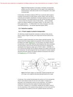
1.1.5 USDA and FEMA Coastal Construction Manual Bearing Capacity Data
USDA and FEMA Coastal Construction Manual data include bearing capacity data, shear strength
and angle of internal friction data, and grading of various types of soils as excellent, fair to good, or
poor.
Table 7 Engineering Properties of Soils
Soil Group
Group I
Excellent
Group II
Fair to Good
Group III
Poor
Unified
Soil
Classification
Symbol
Bearing Capacity (psf)
Undrained Shear
Strength1 (psf)
Angle of Internal
Friction (degrees)
GW
2,700-3,000
NA
38-46
GP
2,700-3,000
NA
38-46
SW
800-1,200 (loose)
NA
30-46 (loose to dense)
SP
800- 1,200 (loose)
NA
30-36 (loose to dense)
GM
2,700-3,000
NA
38-46
SM
1,600-3,500 (firm)
NA
28-40 (firm)
GC
2,700-3,000
NA
38-46
sc
1,600-3,500 (firm)
NA
30-34 (dense)
ML
2,000
NA
30-34 (dense)
CL
600- 1,200 (soft)
3,000-4,500 (stiff)
0-250 (soft)
1,000- 1,200 (stiff)
NA
CH
600- 1,200 (soft)
3,000-4,500 (stiff)
250-500 (soft)
2,000-4,000 (stiff)
NA
MH
2,000
1,600
NA
Source: Table modified from the U.S. Department of Agriculture (www.usda.gov), FEMA Coastal
Construction Manual (www.fema.gov), and Bardet, J. (1997). Experimental Soil Mechanics. PrenticeHall.
1
The undrained shear strength is also commonly referred to as cohesion in saturated clays,
psf = pounds per square foot NA = not applicable
1.1.6 Typical Soil Bearing Capacity Categories
Typical soil bearing capacities can be roughly categorized as follows:
• Crystalline bedrock
12,000 pounds per square foot
• Sedimentary rock
6,000 pounds per square foot
• Sandy gravel or gravel
5,000 pounds per square foot
• Sand, silty sand, clayey sand, silty gravel
3,000 pounds per square foot
• Clay, sandy clay, silty clay
2,000 pounds per square foot
Source: Table 401.4.1, CABO-1 & 2 Family Houses Code, 1995.
www.EngineeringEBooksPdf.com
Soils, Site Utilities, Sitework Equipment
13
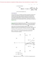
1.2.0 Soil Test Boring Report
The geotechnical report assembled by an owner when a new construction project is anticipated will
include test borings to acquaint bidding contractors with the general nature of the site’s subsurface
conditions.
LOG OF BORING No. B-1
DATE: 6-22-99
CLIENT:
SITE:
#02995604
RIG: CME 75
PROJECT:
DESCRIPTION
PA
6" GRAVEL
LEAN CLAY, siltv trace oraanics.
gray brown, trace dark brown and
red brown, medium (Possible Fill)
CL
1
SS
HS
14
7
34.1
2000*
45,21,34
10
CL
2
SS
HS
6
5
18.6
7000*
45,23,22
15
CL
3
SS
HS
24
g
24.1
5500*
20
CL
4
SS
HS
24
10
22.3
3500*
25
CL
5
SS
HS
24 _, 5
27.6
2500*
LEAN CLAY, silty, gray brown,
trace dark brown, stiff to very stiff
30
CL
6
SS
HS
24
19
26.5
5000*
Trace limonites at 34.0'
35
CL-CH
7
SS 24
HS
14
23.5
5000*
5
LEAN CLAY, calcareous, trace
sand and limestone gravel dark
brown, brown, very stiff (Possible
Fill)
LEAN CLAY, trace silt, qrav
brown, trace dark gray, red brown
and dark brown, stiff to very stiff
LEAN TO FAT CLAY, arav brown,
trace dark brown, very stiff
44,20,24
42,18,24
1.2.1 Stratum Description Column in Boring Log
A stratum description column is included in the boring log and makes reference to soils description
in more general terms, such as topsoil, gravel, and dense or medium sand. This log and report is often
accompanied by the civil engineer’s soils classification terminology that mostly parallels that of the
USC and includes a component gradation designation and a fines fraction chart.
www.EngineeringEBooksPdf.com
14
Section 1
1.2.1.1 Fines Fraction, Plasticity
Fines fraction, plasticity, component gradation terms, and density/consistency tables accompany the
civil engineer’s soils report. The smallest thread diameter rolled portion of the table refers to the
smallest diameter the soil sample can be rolled into by hand.
COMPONENT GRAE¥ATION TERMS
MATERIAL
FRACTION
SIEVE SIZE
GRAVEL
COARSE
3/4" TO 3"
FINE
NO. 4 TO 3/4"
COARSE
NO. 10 TO NO. 4
MEDIUM
NO. 40 TO NO. 10
FINE
NO. 200 TO NO. 40
SAND
PASSING NO. 200
FINES
FINES FRACTION
PLASTICITY
PI
NAME
SMALLEST
THREAD DIA
ROLLED
NON-PLASTIC
0
SILT
NONE
SLIGHT
1-5
Clayey SILT
1/4"
LOW
5-10
SILT & CLAY
1/8"
MEDIUM
10-20
CLAY & SILT
1/16"
HIGH
20-40
Silty CLAY
1/32"
VERY HIGH
>40
CLAY
1/64"
1.2.1.2 Bedrock Weathering Classifications
BEDROCK WEATHERING CLASSIFICATION
GRADE
SYMBOL
Fresh
F
No visible signs of decomposition or discoloration. Rings under hammer
impact.
Slightly Weathered
WS
Slight discoloration inwards from open fracture!;, otherwise similar to F.
Moderately Weathered
WM
Discoloration throughout. Weaker minerals such as feldspar decomposed.
Strength somewhat less than fresh rock but cores cannot be broken by hand or
scraped by knife. Texture preserved.
Highly Weathered
WH
Most minerals somewhat decomposed. Specimens can be broken by hand with
effort or shaved with knife. Core stones present in rock mass. Texture
becoming indislinct but fabric preserved.
Completely Weathered
we
Residual Soil
RS
DIAGNOSTIC FEATURES
Minerals decomposed to soil but fabric and structure preserved (Saprolitc).
Specimens easily crumbled or penetrated.
Advanced slate of decomposition resulting in plastic soils. Rock fabric and
structure completely destroyed. Large volume change.
www.EngineeringEBooksPdf.com
Soils, Site Utilities, Sitework Equipment
15
1.2.1.3 Mechanical Properties of Rock
TABLE 1.
Young's
Modulus at
Zero Load
(105 kg/cm2)
Rock
Granite
Microgranite
Syenite
Diorite
Dolerite
Gabbro
Basalt
Sandstone
Shale
Mudstone
Limestone
Dolomite
Coal
Quartzite
Gneiss
Marble
Slate
Note:
1.
2.
3.
MECHANICAL PROPERTIES OF VARIOUS ROCKS
2-6
3-8
6-8
7-10
8-11
7-11
6-10
0.5-8
1-3.5
2-5
1 -8
4-8.4
1-2
Bulk Density
(g/cm3)
Porosity
(percent)
Compressive
Strength
(kg/cm2)
Tensile
Strength
2.6-2.7
0.5-1.5
1,000-2,500
70-250
3.0-3.05
3.0-3.1
2.8-2.9
2.0-2.6
2.0-2.4
0.1-0.5
0.1-0.2
0.1-1.0
5-25
10-30
1,800-3,000
2,000-3,500
1,000-3,000
1,500-3,000
200-1,700
100-1,000
150-300
150-350
150-300
100-300
40-250
20-100
2.2-2.6
2.5-2.6
5-20
1-5
2.65
2.9-3.0
2.6-2.7
2.6-2.7
0.1-0.5
0.5-1.5
0.5-2
0.1-0.5
300-3,500
800-2,500
50-500
1 ,500-3,000
500-2,000
1,000-2,500
1,000-2,000
50-250
150-250
20-50
100-300
50-200
70-200
70-200
(kg/cm2)
For the igneous rocks listed above Poisson's ratio is approximately 0.25.
For a certain rock type, the strength normally increases with increase in density and
increase in Young's modulus. (After Farmer, 1968)
Taken from "Foundation Engineering Handbook" by Winterkorn and Fong, Van
Nostrand Reinhold, pg. 72.
By permission: Atlas Systems, Inc., Independence, Missouri.
1.3.0 Soil Compaction Methods
Soil compaction is simply the method by which the density of soil can be increased by mechanical or
often natural ways. Ponding of water on shallow layers of soil can cause soil consolidation, as can
placing an overburden on soils that were previously excavated and placed in an area where compacted soil is required. Both of these methods are time-consuming and not very practical on the typical fast-moving construction project.
Compacting soils accomplishes a number of things:
• It provides structural integrity to the soil, thereby increasing its load-bearing capacity.
• It prevents later settlement of nonstructural soils.
• It reduces water seepage and the resultant heave and contraction.
Soils can be compacted by various types of mechanical action:
• Vibration. A downward force is created by rotating a concentric weight or piston attached to a
roller.
• Static. Weight is merely applied by the force of a heavy piece of equipment rolling back and forth
across the area to be compacted.
• Impact. This is a repeated ramming action.
www.EngineeringEBooksPdf.com
16
Section 1
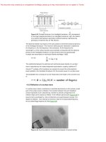
1.3.1 Soil Compaction Equipment
Compaction machines produce two types of forces: frequency and amplitude. Frequency is the
speed at which an eccentric shaft within the compaction machine rotates and is expressed as vibrations per minute (VPM). Amplitude is the maximum movement of the vibrating body from one axis
to another. A machine with double amplitude exhibits that movement in both directions from its axis.
1.3.1.1 Flat Plate Compactor
1.3.1.2 Rammer-Type Compactor
www.EngineeringEBooksPdf.com