Electric Machines and Drives Part 2 docx
Bạn đang xem bản rút gọn của tài liệu. Xem và tải ngay bản đầy đủ của tài liệu tại đây (2.35 MB, 20 trang )
Premium Efficiency Motors
9
now Eff3 disappears in the new classification. This new classification will be probably soon
adopted worldwide in place of regional or local classification, as illustrated in table 1. This
new standard defines efficiency classes and their containing minimum values (conditions).
Efficiency Class IEC USA/Canada CEMEP China
Super Premium
efficiency
IE4 - - -
Premium efficiency IE3 NEMA Premium - -
High efficiency IE2 EPAct EFF1 Class 1
Standard efficiency IE1 - EFF2 Class 2
Below standard
efficiency
- - EFF3 Class 2
Table 1. International motor efficiency classification
6. Life cycle cost Premium motors
An electric motor is somewhat cheap to buy, but expensive to run. For example, a 3 hp
Premium efficiency motor functioning 6 000 hours per year consumes about 1000 $ of
electricity at $0.07/kWh. The purchase price for such a motor is about 500 $ and over the
motor’s 15-year life, the acquisition price represents only 3 % of the lifetime costs, while the
cost of electricity accounts for 97 %. Finally, a 2 % increase in Premium motor efficiency over
EFF1 translates in energy savings over that time nearly twice the cost difference. In addition,
with a larger motor, the saving potential will be larger, and therefore payback periods
would be shortened. For the 100 Hp motor, the acquisition price represents only 1 % of the
lifetime costs, while the cost of electricity accounts for 99 %!!! Fig. 4 depicts typical lifetime
cycle cost motor in the conservative case (Benhaddadi & Olivier, 2010a).
The average life cycle of the small power motors is of the order of 15 years, i.e. the
equivalent of the average car range. The fundamental difference is in the fact that during
this period, the cost of the electricity will represent 97 % of the cost of useful life cycle of the
electric motor, while for the car motor, it represents only 10 %. Moreover, the car’s internal
combustion motors can rarely overcome 50 % efficiency, with an enormous negative impact
to be paid in environmental pollution. We can deduct from this fact that the improvement of
1 % of the electrical motor efficiency will have the same impact as the reduction of the 10 %
gas consumption car.
Moreover, the Canadian electricity costs are presently up to two times cheaper than elsewhere
and high electricity prices reduce payback period. In addition, some Canadian utility
companies and public agencies like Hydro Québec in Québec offer rebate programs to
encourage customers to upgrade their standard motors to Premium efficiency (Benhaddadi &
Olivier, 2010b). For motors from 1 to 75 hp, this program allows 600 $/hp to the customer and
150 $/hp to the distributor for each saved hp. Unfortunately, as a consequence of the lack of
energy saving importance, the purchase of a new motor, as well as the rewinding of defective
standard-efficiency motors, the choice of the motor is often driven by short term investment
considerations, not on the cost of the electricity which can be saved.
The first law for energy efficient motors is the Energy Policy Act (EPAct) which mandates
strict energy efficiency standards for electrical appliances and equipment. This law was first
adopted in USA and became effective in Canada with the adoption of Standard CAN/CSA-
Electric Machines and Drives
10
C390-98. Today more than 75 % of the motors sold in North America are Premium efficiency
and EPAct machines. This clearly indicates the positive effect of the energy law. In light of
the above, and taking into consideration the very slow market transformation with just
voluntary and incentive measures, there’s no doubt that Premium motors will monopolize
the dominant part of the market in the near 2013 future. This is well illustrated in fig. 3.
There is no doubt that the appropriate legislation is the best way of achieving that goal
(Benhaddadi & Olivier, 2009b). Only the latest energy efficient motor technologies should be
manufactured and used. In general terms, North America is not on the leading edge for
energy saving and conservation. Motor efficiency is an exception that should be at least
maintained by EISA law implementation.
Fig. 4. Lifetime motor cost
7. Barriers to high efficiency motors market penetration
Despite the colossal energy saving potential and financial incentives programs, many
companies are still reticent to invest in energy-efficiency motors. The reasons why the well-
known potential for energy saving energy is not exploited have been investigated, and the
authors have identified several reasons why this potential is not yet fully exploited. The
Grand paradox is that cost effective measures are not taken because of several illogical
barriers. So, the most important barriers to high efficiency motors promotion are
(Benhaddadi & Olivier, 2008a):
• The energy costs are relatively so small that energy efficiency improvement isn’t taken
into consideration,
• Lower priority of energy savings importance, when other factors such as availability
service, reliability, and first costs are of premium importance,
• Industry reluctance to change what is, a priori, a good functioning system,
• Doubt about success of energy efficiency programs, or the discount rates used to justify
energy efficiency programs are too low,
Premium Efficiency Motors
11
• Downtime replacement cost look like peanuts, but shutdown time to install new
equipment is expensive and many companies don’t accept this inconvenient,
• Reduced budget often makes reducing energy consumption as « poor parent »,
inducing a lack of encouragement to make a decision,
• Implementing making-decision responsibility is often shared with many internal
conflicting pressures and divergence and ultimate choice don’t always belong to
electrician engineers, who are energy savings conscious,
• Distributors regularly represent two or more motor manufacturers and they can
advantage products from the manufacturer that offers the highest discount rather than
high-efficiency ones,
• Usual predisposition to use stocked old motors rather than purchase high efficiency
ones,
• It is not economically pragmatic to change a motor until it fails,
• Penchant to have the failed motor repaired rather than replaced by high efficiency ones,
• Degradation efficiency of repaired motor cannot be simply illustrated,
• Annual running hours are not sufficiently high to induce satisfactory payback.
8. Incentive policies to overcome barriers
Experience derived from many energy saving initiatives around the world showed that the
most successful programs are based on a combination of technical and promotional
information, educational tools and financial incentives. If technicians and engineers would
be trained in system design integration and least lifecycle cost as a goal, no doubt that the
problem of inefficient industrial equipment should be solved (Benhaddadi & Olivier, 2008a).
Consequently, to overcome the identified obstacles need a combination of the following
measures:
• Premium priority: For the companies, the energy saving status has to arrive at
legislative endorsement, like is the case for safety and quality insurance,
• Incentive programs: to reinforce energy savings promotion politics, much higher
discount rates should be used to evaluate the cost-effectiveness of energy efficiency
policies, programs or measures,
• Highlighted information and diffusion: this information must be of practical value, and
sufficiently demonstrative with real pilot projects,
• Environmental concern: It’s necessary to reinforce ecological policy criteria and support
environmental friendly companies. This follows the principle that the saved energy is
the most environmentally friendly one. A particularly promising concept is the
emissions trading scheme, which could be enable companies to claim emissions credits
for investments that reduce energy consumption,
• Legislation: to legislate against recalcitrant and to impose to market the gradual
approach of the « carrot and the stick », where the carrot represents the incentives and
the stick stands for refractory.
The authors strongly believed in the need to enhance policy measures aimed at reducing the
demand for energy and the resultant environmental impact. We therefore welcome the
increased interest in energy conservation in Canada. But, the accumulated experience clearly
show that putting in place incentives and voluntary measures for the energy efficiency of
electric motors is not sufficient, as it is prerequisite to implement mandatory measures for
Electric Machines and Drives
12
larger market penetration (fig. 5). The carbon savings from this measure have the potential
to make a significant contribution to emissions target reduction.
Fig. 5. Incentives, voluntary and mandatory measures impact
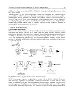
9. Experimental setup and results
Figure 6 depicts the experimental laboratory set-up. The motors are fed by three single
phase autotransformers and direct torque control, DTC drives. The motors are mechanically
loaded by dc machine connected through a precision torque-speed transducer. A
motor/harmonic power meter is used for measuring real and reactive power, currents,
voltages and power factor. The motors are mechanically loaded by dc machine connected
through a high precision torque-speed transducer.
The measurements were taken in similar conditions and each motor was loaded until
thermal equilibrium was reached, while each of the two benches can be used to determine
the efficiency.
The two benches are sufficiently flexible and require minimum adjustments when different
Premium motors are tested (Benhaddadi et al. 2010b). Several 3 hp Premium motors from
different 3 manufacturers were tested. Figures 7 and 8 show the stators and rotors of the
three different motors.
The measurements were taken in similar conditions and each motor was loaded until
thermal equilibrium was reached.
For each of the motors B & C, Fig. 9 shows the variation of the efficiency versus the
mechanical torque in the case of direct 60 Hz feeding, without drive. The results for motor A
are not provided, as they are the same as for the motor B. One can deduct that when the
motors are feed from the rated 230 V grid, the difference between the measured efficiency at
rated load and the nameplate value is less a 0.2 %,. But, most electric motors are designed to
function at 50 % to 100 % of rated value. Fig. 9 also shows that maximum Premium motor
Premium Efficiency Motors
13
Fig. 6. Measurement setup with instrumentation
efficiency is near 75 % of rated load, and tends to decrease substantially below about 50 %
load. Moreover, experienced overloaded motors don’t significantly lose efficiency, as they
are designed with a 1.15 factor service. It’s also relevant to notice that the two motors give
the same efficiency value just for the rated regime, as this efficiency difference is significant
(1.5 %) when the motor is under loaded (Benhaddadi et al. 2010b).
Next step is to analyze the feeding voltage impact. The voltages choice are made taking into
account practical considerations: 230V, and 200.
• The first one is the motor nameplate indication, which is in accordance with an
industrial available 240 V feeding voltage,
• The second one is the real full-time laboratory available voltage. These two voltages
were obtained with three one-phase transformers.
The experimental results obtained in the grid feeding case (without drive) and illustrated in
fig. 10 show that feeding voltage has an important impact on efficiency value. With rated
230 V voltage and load values, efficiency is 89.3 %, i.e. 0.2 % less than nameplate value.
When the feeding voltage is decreased to 208 V and 200 V values, the efficiency decrease up
to 2 %. So, additional losses occur when a 230 V motor is operated at or below 208 volts. The
motor show lower full-load efficiency, slips more, and produces less torque.
In another hand, the ASD (adjustable speed drive) deployment to control motor can
substantially reduce energy consumption. The ASD advantages and energy consumption
reduction are nowadays well documented (Benhaddadi & Olivier, 2007). But, at the present
Electric Machines and Drives
14
Fig. 7. Stator Premium motors
Fig. 8. Rotor Premium motors
Premium Efficiency Motors
15
time, many companies use ASD to feed their motors, whenever they don’t need speed
regulation. In the energy saving point of view, we must be careful with this making-
decision, as ASD introduces supplementary losses in the motor and the drive. As can be
seen in fig. 11 and 12, the drive introduces a noticeable reduction of the motor system
efficiency. This decrease reaches approximately 4 % in the rated regime, withdrawing totally
energy savings induced by Premium efficiency motor use. Further investigations to
correctly understand the extents of the losses introduced by the controller for all frequencies
are under consideration.
The other problem is that if Premium motors are misapplied, they may not achieve
predicted energy savings and may result in diminished performance efficiency. For
centrifugal pumps, an increase in operating speed will increase the required power by the
third power of the speed ratio. For example, by substituting Premium 1760 rpm motor to
EPAct 1740 rpm one, a 20 rpm increase in the speed induce 3.5 % increase in the load, as
(1760 ÷ 1740)
3
= (1.014)
3
= 1.035. So, when replacing a standard efficiency motor, one must be
careful, as a Premium motor with lower or equal full-load speed must be selected to avoid
the energy increase that may negate the predicted energy savings resulting from a higher
efficiency.
It’s important to notice that to date, there is no agreement that allows the determination of
ASD system efficiency at any given frequency. The ideal situation is to obtain a family of
efficiency curves for diverse torques and frequencies, including overrated values, as
experimentally illustrated in fig. 13.
Fig. 9. Manufacturing technology impact Fig. 10. Viltage feeding impact
Electric Machines and Drives
16
Fig. 11. Drive impact Fig. 12. Drive impact
But, to generalize results, there are two difficulties: the first one can be illustrated by the
results presented in fig.14, where we can see that the same 3 Hp motors issued from two
different manufacturers can have the same efficiency for 60 Hz frequency feeding voltage,
but different efficiency for another 30 Hz frequency (fig. 14). For each of these two motors B
& C, Fig. 14 shows the variation of the efficiency versus the mechanical torque. In the 60 Hz
case, the difference between the measured efficiency at rated load is negligible, while it
reaches 2 % in the 30 Hz feeding frequency.
The second difficulty is about 50-60 Hz feeding frequency dilemma. As earlier illustrated, 50
Hz frequency gives better efficiency beginning from 2/3 load, while 60 Hz is better for low
loads. It’s noticeable that the same results were obtained for Motor B.
Considering that for the same frequency, two Premium motors issued from two different
manufacturers can show significantly different efficiency in low frequencies, one must be
careful in generalizing the conclusions of this research. Moreover, the same motor tested for
different frequencies can yield to different losses repartitions. So, before claiming that the
obtained results are, or are not in agreement with findings of other authors, several other
Premium efficiency motors from different constructors should be tested. The mentioned
work is under consideration.
10. Conclusions
In the future sustainable energy mix, a key role will be reserved for electricity, as GHG
emissions reduction in this sector has to be drastically reduced. In this option, obvious
Premium Efficiency Motors
17
conclusion is that large market penetration Premium motors needs a complex approach
with a combination of financial incentives and mandatory legal actions, as industry doesn’t
invest according to least life cycle costs.
The US Energy Policy Act and the Canadian Energy Efficient Act, along with the
implementation of NEMA Premium efficiency levels, have lead to North American
leadership on motor efficiency implementation. In general terms, North America is not on
the leading edge for energy saving and conservation. Motor efficiency is an exception that
should be at least maintained. Next step is to get Tax incentives to promote early retirement
of older inefficient pre-EPAct motors by replacing instead of repairing
Experimental comparison of the performance characteristics of 3 hp Premium efficiency
induction motors has been presented. The motors were tested according to Standard IEEE
112-B. In the rated frequency and voltage case, the experimental results are in good
agreement with nameplate manufacturer’s information. Particularly, a comparison of the
rated operating point shows that, the discrepancy is approximately 0.2 %.
However, in low voltage/frequency applications, the use of a variable speed drive
introduces extra losses and the overall efficiency can be noticeably reduced. The
experimental results show that feeding voltage has an important impact on efficiency value,
while efficiency at low frequencies depends on a certain level at manufacturer technology.
From a global energy saving point of view, the ASD application to Premium efficiency
motors should be promoted just when adjustable speed is needed.
Fig. 13. Frequency impact
Fig. 12. Frequency & manufacturing
technology impact
Electric Machines and Drives
18
2 Pole 4 Pole 6 Pole 8 Pole 2 Pole 4 Pole 6 Pole 8 Pole
1.0 0.0 82.5 80.0 74.0 75.5 82.5 80 74
1.5 82.5 84.0 84.0 75.5 82.5 84 85.5 77
2.0 84.0 84.0 85.5 85.5 84 84 86.5 82.5
3.0 84.0 86.5 86.5 86.5 85.5 87.5 87.5 84
5.0 85.5 87.5 87.5 87.5 87.5 87.5 87.5 85.5
7.5 87.5 88.5 88.5 88.5 88.5 89.5 89.5 85.5
10.0 88.5 89.5 90.2 89.5 89.5 89.5 89.5 88.5
15.0 89.5 91.0 90.2 89.5 90.2 91 90.2 88.5
20.0 90.2 91.0 91.0 90.2 90.2 91 90.2 89.5
25.0 91.0 91.7 91.7 90.2 91 92.4 91.7 89.5
30.0 91.0 92.4 92.4 91.0 91 92.4 91.7 91
40.0 91.7 93.0 93.0 91.0 91.7 93 93 91
50.0 92.4 93.0 93.0 91.7 92.4 93 93 91.7
60.0 93.0 93.6 93.6 92.4 93 93.6 93.6 91.7
75.0 93.0 94.1 93.6 93.6 93 94.1 93.6 93
100.0 93.0 94.1 94.1 93.6 93.6 94.5 94.1 93
125.0 93.6 94.5 94.1 93.6 94.5 94.5 94.1 93.6
150.0 93.6 95.0 94.5 93.6 94.5 95 95 93.6
200.0 94.5 95.0 94.5 93.6 95 95 95 94.1
250.0 94.5 95.4 95.4 94.5 95.4 95 95 94.5
300.0 95.0 95.4 95.4 94.5 95.4 95.4 95 0
350.0 95.0 95.4 95.4 94.5 95.4 95.4 95 0
400.0 95.4 95.4 0.0 0.0 95.4 95.4 0 0
450.0 95.8 95.8 0.0 0.0 95.4 95.4 0 0
500.0 95.8 95.8 0.0 0.0 95.4 95.8 0 0
HP
ODP TEFC
Annex 1. NEMA MG-1 Table 12-11 Full-Load Efficiencies of Energy Efficient Motors (EPAct)
Premium Efficiency Motors
19
2 Pole 4 Pole 6 Pole 2 Pole 4 Pole 6 Pole
1 77 85.5 82.5 77 85.5 82.5
1.5 84 86.5 86.5 84 86.5 87.5
2 85.5 86.5 87.5 85.5 86.5 88.5
3 85.5 89.5 88.5 86.5 89.5 89.5
5 86.5 89.5 89.5 88.5 89.5 89.5
7.5 88.5 91 90.2 89.5 91.7 91
10 89.5 91.7 91.7 90.2 91.7 91
15 90.2 93 91.7 91 92.4 91.7
20 91 93 92.4 91 93 91.7
25 91.7 93.6 93 91.7 93.6 93
30 91.7 94.1 93.6 91.7 93.6 93
40 92.4 94.1 94.1 92.4 94.1 94.1
50 93 94.5 94.1 93 94.5 94.1
60 93.6 95 94.5 93.6 95 94.5
75 93.6 95 94.5 93.6 95.4 94.5
100 93.6 95.4 95 94.1 95.4 95
125 94.1 95.4 95 95 95.4 95
150 94.1 95.8 95.4 95 95.8 95.8
200 95 95.8 95.4 95.4 96.2 95.8
250 95 95.8 95.4 95.8 96.2 95.8
300 95.4 95.8 95.4 95.8 96.2 95.8
350 95.4 95.8 95.4 95.8 96.2 95.8
400 95.8 95.8 95.8 95.8 96.2 95.8
450 95.8 96.2 96.2 95.8 96.2 95.8
500 95.8 96.2 96.2 95.8 96.2 95.8
HP
ODP TEFC
Annex 2. NEMA MG-1 Table 12-12 Full-Load Efficiencies for 60 Hz NEMA Premium
Efficient Electric Motors Rated 600 Volts or less
Electric Machines and Drives
20
246 246
0.75 1 72.1 72.1 70.0 0.75 1 77.0 78.0 73.0
1.1 1.5 75.0 75.0 72.9 1.1 1.5 78.5 79.0 75.0
1.5 2 77.2 77.2 75.2 1.5 2 81.0 81.5 77.0
2.2 3 79.7 79.7 77.7 2.2 3 81.5 83.0 78.5
3 4 81.5 81.5 79.7 3 4 84.5 85.0 83.5
4 5.5 83.1 83.1 81.4 4 5.5 86.0 87.0 85.0
5.5 7.5 84.7 84.7 83.1 5.5 7.5 87.5 87.5 86.0
7.5 10 86.0 86.0 84.7 7.5 10 87.5 88.5 89.0
11 15 87.6 87.6 86.4 11 15 88.5 89.5 89.5
15 20 88.7 88.7 87.7 15 20 89.5 90.5 90.2
18.5 25 89.3 89.3 88.6 18.5 25 89.5 91.0 91.0
22 30 89.9 89.9 89.2 22 30 90.2 91.7 91.7
30 40 90.7 90.7 90.2 30 40 91.5 92.4 91.7
37 50 91.2 91.2 90.8 37 50 91.7 93.0 91.7
45 60 91.7 91.7 91.4 45 60 92.4 93.0 92.1
55 75 92.1 92.1 91.9 55 75 93.0 93.2 93.0
75 75 92.1 92.1 91.9 75 75 93.0 93.2 93.0
90 125 92.7 92.7 92.6 90 125 93.0 93.5 94.1
110 150 93.0 93.0 92.9 110 150 94.1 94.5 94.1
132 175 93.3 93.3 93.3 150 200 94.1 94.5 94.1
160 215 93.5 93.5 93.5 185 250 94.1 94.5 94.1
200 270 93.8 93.8 93.8 200 270 94.1 94.5 94.1
260 350 94.0 94.0 94.0 260 350 94.1 94.5 94.1
300 400 94.0 94.0 94.0 300 400 94.1 94.5 94.1
335 450 94.0 94.0 94.0 335 450 94.1 94.5 94.1
375 500 94.0 94.0 94.0 375 500 94.1 94.5 94.1
PolesRating
(hp)
Rating
(kW)Rating (kW)
Rating
(hp)
Poles
Table 3. Standard Efficiency IE1 50Hz Table 4. Standard Efficiency IE1 60Hz
Annex 3. CEI efficiencies
Premium Efficiency Motors
21
246 246
0.75 1 77.4 79.6 75.9 0.75 1 75.5 82.5 80.0
1.1 1.5 79.6 81.4 78.1 1.1 1.5 82.5 84.0 85.5
1.5 2 81.3 82.8 79.8 1.5 2 84.0 84.0 86.5
2.2 3 83.2 84.3 81.8 2.2 3 85.5 87.5 87.5
3 4 84.6 85.5 83.3 3.7 5 87.5 87.5 87.5
4 5.5 85.8 86.6 84.6 5.5 7.5 88.5 89.5 89.5
5.5 7.5 87.0 87.7 86.0 7.5 10 89.5 89.5 89.5
7.5 10 88.1 88.7 87.2 11 15 90.2 91.0 90.2
11 15 89.4 898.0 88.7 15 20 90.2 91.0 90.2
15 20 90.3 90.6 89.7 18.5 25 91.0 92.4 91.7
18.5 25 90.9 91.2 90.4 22 30 91.0 92.4 91.7
22 30 91.3 91.6 90.9 30 40 91.7 93.0 93.0
30 40 92.0 92.3 91.7 37 50 92.4 93.0 93.0
37 50 92.5 92.7 92.2 45 60 93.0 93.6 93.6
45 60 92.9 93.1 92.7 55 75 93.0 94.1 93.6
55 75 93.2 93.5 93.1 75 75 93.6 94.5 94.1
75 75 93.8 94.0 93.7 90 125 94.5 94.5 94.1
90 125 94.1 94.2 94.0 110 150 94.5 95.0 95.0
110 150 94.3 94.5 94.3 150 200 95.0 95.0 95.0
132 175 94.6 94.7 94.6 185 250 95.4 95.4 95.0
160 215 94.8 94.9 94.8 200 270 95.4 95.4 95.0
200 270 95.0 95.1 95.0 260 350 95.4 95.4 95.0
260 350 95.0 95.1 95.0 300 400 95.4 95.4 95.0
300 400 95.0 95.1 95.0 335 450 95.4 95.4 95.0
335 450 95.0 95.1 95.0 375 500 95.4 95.4 95.0
375 500 95.0 95.1 95.0
Rating (kW)
Rating
(hp)
Poles Rating
(kW)
Rating
(hp)
Poles
Table 5. High Efficiency IE2 50Hz Table 6. High Efficiency IE2 60Hz (EPACT)
Annex 3. CEI efficiencies
Electric Machines and Drives
22
246
0.75 1 80.7 82.5 78.9
1.1 1.5 82.7 84.1 81.0
1.5 2 84.2 85.3 82.5
2.2 3 85.9 86.7 84.3
3 4 87.1 87.7 85.6
4 5.5 88.7 88.6 86.8
5.5 7.5 89.2 89.6 88.0
7.5 10 90.1 90.4 89.1
11 15 91.2 91.4 90.3
15 20 91.9 92.1 91.2
18.5 25 92.4 92.6 91.7
22 30 92.7 93.0 92.2
30 40 93.3 93.6 92.9
37 50 93.7 93.9 93.3
45 60 94.0 94.2 93.7
55 75 94.3 94.6 94.1
75 75 94.7 95.0 94.6
90 125 95.0 95.2 94.9
110 150 95.2 95.4 95.1
132 175 95.4 95.6 95.4
160 215 95.6 95.8 95.6
200 270 95.8 96.0 95.8
260 350 95.8 96.0 95.8
300 400 95.8 96.0 95.8
335 450 95.8 96.0 95.8
375 500 95.8 96.0 95.8
Rating (kW)
Rating
(hp)
Poles
()
246
0,75 1 77,0 85,5 82,5
1,1 1,5 84,0 86,5 87,5
1,5 2 85,5 86,5 88,5
2,2 3 86,5 89,5 89,5
3,7 5 88,5 89,5 89,5
5,5 7,5 89,5 91,7 91,0
7,5 10 90,2 91,7 91,0
11 15 91,0 92,4 91,7
15 20 91,0 93,0 91,7
18,5 25 91,7 93,6 93,0
22 30 91,7 93,6 93,0
30 40 92,4 94,1 94,1
37 50 93,0 94,5 94,1
45 60 93,6 95,0 94,5
55 75 93,6 95,4 94,5
75 75 94,1 95,4 95,0
90 125 95,0 95,4 95,0
110 150 95,0 95,8 95,8
150 200 95,4 96,2 95,8
185 250 95,8 96,2 95,8
200 270 95,8 96,2 95,8
260 350 95,8 96,2 95,8
300 400 95,8 96,2 95,8
335 450 95,8 96,2 95,8
375 500 95,8 96,2 95,8
Rating
(kW)
Rating
(hp)
Poles
Table 7. Premium Efficiency IE3 50Hz
Table 8. Premium Efficiency IE3 60Hz
(NEMA Premium)
Annex 3. CEI efficiencies
Annex 4: Acronyms
• ASD Adjustable speed drives
• ACEEE American Council for and Energy Efficient Economy
• CEE Consortium for Energy Efficiency
• DOE Department of Energy
• EISA Energy Independence & Security Act
• EPAct Energy Policy act
• EU European Union
• GHG Greenhouse gas emissions
• IPCC International Panel on climate change
• OEM Original equipment manufacturer
• MG 1 Motor Generator
• MEPS Minimum energy performance standard MEPS
• MDM Motor Decisions Matter (MDM
• NEMA National Electrical Manufacturers Association
Premium Efficiency Motors
23
11. References
Aoulkadi, M., Binder, A.: “Evaluation of different measurement methods to determine stray
load losses in induction machines,”. IEEE Trans. On Industrial Electronics, vol. 2
No 1, 2008
Benhaddadi M., Olivier G.: (2010a) “La promotion de l’économie d’énergie électrique passe
par son juste prix,”. 79
e
Congrès de l’AFAS, Montréal, Canada, 2010
Benhaddadi M., Olivier G., and Yelle J.: (2010b) “Premium efficiency motors effectiveness,”.
IEEE International symposium on power electronics, electrical drives, automation
and motion SPEEDAM 2010, Pisa, Italy, 2010
Benhaddadi M., Olivier G., Labrosse D., Tétrault P.: (2009a) “Premium efficiency motors and
energy saving potential,”. IEEE International electric machines and drives
conference, IEEE_IEMDC, Miami, USA, 2009
Benhaddadi M., Olivier G.: (2009b) “L’économie d’énergie : une affaire de législation,”.
Communication présentée au 78
e
Congrès de l’ACFAS, Ottawa, Canada, 2009
Benhaddadi M., Olivier G.: (2008a) “Barriers and incentive policies to high-efficiency motors
and drives market penetration,”. IEEE International symposium on power
electronics, electrical drives, automation and motion SPEEDAM 2008, Ischia, Italy,
Benhaddadi M., Olivier G.: (2008b) “Le génie électrique à la rescousse des économies
d’énergie dans l’industrie,”. Communication présentée au 76
e
Congrès de l’ACFAS,
Québec, Canada, 2008
Benhaddadi M., Olivier G.: (2008c) “Dilemmes énergétiques,”. Presses de l’Université du
Québec, Québec, 2008, 216p.
Benhaddadi, M., Olivier G.: (2007) “Energy savings by means of generalization adjustable
speed drive Utilization,”. IEEE Canadian Conference on Electrical and Computer
Engineering, Vancouver, 2007.
Benhaddadi M., Olivier G.: (2004) “Including Kyoto in electrical engineering curriculum,”.
IEEE Canadian Conference on Electrical and Computer Engineering, Niagara Falls,
2004
Boglietti, A. Cavagnino, A. Lazzari, M. Pastorelli, , M.: (2004) “International standards for
the induction motor efficiency evaluation: a critical analysis o A. f the stray-load
loss determination,”. IEEE Trans. On Industry Appl., vol.40, No 5, 2004
Bonnett, A.H., Yung, C.: (2008) “Increased efficiency versus increased reliability: A
comparison of pre-EPAct, EPAct, and premium-efficiency motors,”. IEEE Industry
application Magazine, vol.2, 2008
BP (2010) British Petroleum statistical review of world energy (2010), June 2010
CEE (2007) Energy-efficiency incentive programs: Premium-efficiency motors and
adjustable speed drives in the US and Canada, (2007) prepared by consortium for
energy efficiency, may 2007, www.cee.org
DOE (2010) Energy Information Administration, Official energy statistics from the US
government,
DOE/EIA
Elmeida, A.I. Ferreira, F.FJ. Busch, J.F. Angers P. (2002) “Comparative analysis of IEEE-112 B
and IEC 34-2 efficiency testing standards using stray load losses in low-voltage
three phase cage induction motors,” IEEE Industry applications, March-April 2002,
pp. 608-614
Energy Policy Act EPACT and motor testing understanding, IEEE-112 Method B,
Electric Machines and Drives
24
Evans, B.D., Crissman, J., Gobert, G.: (2008) “Test results for energy savings,”. IEEE Industry
application Magazine, vol.2, 2008
Finlay, W.R. Veerkamp B., Gehring D., and Hanna: P. (2009)“Improving motor efficiency
levels globally,”. IEEE Industry application Magazine, vol.15, 2009
IEA (2010) International Energy Agency, OECD/IEA ./
IEA (2009) The experience with energy efficiency policies and programs in IEA countries:
learning from the critics, (2009) International energy agency information paper,
august 2009
IPCC (2007) Contribution of working group I to the fourth assessment report of the
intergovernmental panel on climate change, summary for policymakers,
Nagorny, A., Wallace, A., Von Jouanne, A.: “Stray load loss efficiency connections,”. IEEE
Industry application Magazine, vol.10, issue 3, may-june 2004
NRC (2004) Energy-efficient motor systems assessment guide, Canadian industry program
for energy conservation (2004), CIPEC, Natural Resources Canada, 2004
Parasiliti, F., Villani, M., Paris, C., Walti, O. Songini, G. Novello, A. Rossi T.: (2004) “Three-
phase induction motor efficiency improvements with die-cast cooper rotor cage
and premium steel,”. IEEE International symposium on power electronics,
electrical drives, automation and motion SPPEDAM 2004, Capri, Italy, 2004
RNC (2004) Ressources Naturelles Canada: (2004) “Guide d’évaluation du rendement des
systèmes moteurs éconergétiques,” RNC, 2004
Renier, B. Hameyer, K., Belmans, R.: (1999) “Comparison standards for determining
efficiency of three phase induction motors,”. IEEE Trans. On Energy Conversion,
vol.14, No 3, 1999
Rooks, J.A., Wallace: (2004) “Energy efficiency of VSDs,” IEEE Industry applications
Magazine, vol.10, issue 3, 2004
UE (2003) Commission Européenne, Direction générale énergie et transport: (2003) “Motor
challenge programme,”. UE, Bruxelles, 2003
2
Electric Motor Performance Improvement Using
Auxiliary Windings and Capacitance Injection
Nicolae D.V
Tshwane University of Technology
South Africa
1. Introduction
Generally, some electric machines such as induction machines and synchronous reluctance
motors require reactive power for operation. While the reactive power required by a
synchronous machine can be taken from the power source or supplied by the machine itself
by adjustment of the field current, the power factor of an induction machine is always
lagging and set by external quantities (i.e., the load and terminal voltage). Poor power
factor adversely affects the distribution system and a cost penalty is frequently levied for
excessive VAr consumption.
Power factor is typically improved by installation of capacitor banks parallel to the motor. If
the capacitor bank is fixed (i.e. that it can compensate power factor only for a fixed load),
when the load is variable, then the compensation is lost. Some authors (El-Sharkawi et al,
1984, Fuchs and Hanna, 2002) introduced the capacitors using thyristor/triac controllers; by
adjusting the firing angle, the capacitance introduced in parallel with the motor becomes
variable and thus compensating the power factor for any load. Other works (Suciu et al,
2000.) consider the induction motor as an RL load and power factor is improved by inserting
a variable capacitor (through a bridge converter) which is adjusted for unity according with
the load. For the above methods, the capacitive injection is directly into the supply. Another
method conceived for slip ring induction motor was to inject capacitive reactive power
direct into the rotor circuit (Reinert and Parsley, 1995; Suciu, et al. 2002).
The injection of reactive power can be done through auxiliary windings magnetically
coupled with the main windings (E. Muljadi et al. 1989; Tamrakan and Malik, 1999;
Medarametla et al. 1992; Umans, and H. L. Hess, 1983; Jimoh and Nicolae, 2006, 2007). This
compensating method has also been applied with good results not only for induction
motors but also for a synchronous reluctance motor (Ogunjuyigbe et al. 2010).
2. Method description
2.1 Physical solution
The method described in this chapter makes use of two three-phase stator windings. One
set, the main winding (star or delta), is connected directly to the source. The other set of
windings - auxiliary, is only magnetically coupled to the main winding. All windings have
the same shape and pitch, but may have different turn numbers and wire sizes; usually
smaller in order to be accommodated in the slots together with the stator. The windings are
Electric Machines and Drives
26
arranged in slots such that there is no phase shift between the two windings. Figure 1 shows
a possible arrangement of the windings for a four pole induction machine.
+A
+A
+A
+X
+X
+X
-Y
-Y
-B
-B
-B
-Y
+Z
+C
+C
+C
+Z
+Z
-A
-X
-X
-X
-A
-A
+B
+Y
+Y
+Y
+B
+B
-C
-Z
-C
-C
-Z
-Z
+A
+X
+X
+X
+A
+A
-B
-Y
-Y
-Y
-B
-B
+C
+Z
+Z
+Z
+C
+C
-A
-X
-X
-X
-A
-A
+B
+Y
+Y
+Y
+B
+B
-C
-Z
-Z
-Z
-C
-C
Fig. 1. High Power factor induction machines-windings arrangement
2.2 Auxiliary windings connections
As mention above, the main winding can have delta or star connection. Figure 2 shows the
main winding connected in star and the auxiliary windings connected in generic (a), star (b)
and delta (c) to the capacitor bank via a static switch.
Figure 3 shows a simpler way to inject capacitive reactive power. In this method, the
auxiliary windings are in “single –phase connection” with the apparent advantage of using
only one capacitor and static switch.
2.3 Variable Capacitors
In order to achieve a compensation for various loading of the machine, the compensating
capacitor should be able to be varied. This capability is obtained through connecting a fixed
capacitor via a static switch. The static switch can be achieved using thyristors or IGBTs in
bidirectional configuration.
Electric Motor Performance Improvement Using Auxiliary Windings and Capacitance Injection
27
V
a
V
b
V
c
Rotor
C
I
a
●
V
x
V
y
V
z
I
b
I
c
*
*
*
*
*
*
Static Switch
(a)
●
●
●
●
●
●
● ●
●
V
a
V
b
V
c
V
z
V
y
V
x
C
z
C
y
C
x
●
●
●
●
●
●
V
a
V
b
V
c
V
x
V
y
V
z
C
x
C
y
C
z
●
●
●
●
(b) (c)
Fig. 2. Auxiliary windings: a) generic connection; b) star connection; c) delta connection
V
a
V
b
V
c
V
a
Rotor
I
ax
C
Static Switch
I
a
●
V
x
V
y
V
z
I
b
I
c
Fig. 3. Auxiliary windings: “single –phase connection”
Electric Machines and Drives
28
2.3.1 Thyristor-based variable capacitor
Figure 4 shows the use of thyristor to accomplish a variable capacitor. The inductor L
r
is
introduced to reduce – limit the surge current; it is relatively small and does not affect the
overall capacitive behaviour.
Th
1
C
L
r
Th
2
Fig. 4. Variable capacitor using bidirectional thyristor
The equivalent capacitance depends on the delay angle. Due to the phase angle control, the
device introduces harmonic currents.
2.3.2 IGBT-based variable capacitor
The above drawback can be address using IGBTs in bidirectional configuration (Figure 5)
and a switching frequency higher then operational frequency (50 Hz).
Fig. 5. IGBT in bidirectional topology
Figure 6 shows a configuration to achieve a variable capacitor using two bidirectional static
switches. The main capacitor C
1
is introduced in the auxiliary winding circuit, via a
bidirectional switch Sw
1
, for a period of time depending on the duty cycle (δ) of the
switching frequency; in this time the bidirectional switch Sw
2
is OFF. When Sw
1
is OFF, the
capacitor is discharged. The reactor L
r
limits the capacitive surge current without affecting
the capacitive behaviour.
C
1
C
2
V
x
I
x
●
Sw
1
Sw
2
●●
●
L
r
Fig. 6. Variable capacitor using two IGBTs in bidirectional topology