Tài liệu Technical Reference pdf
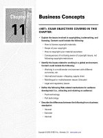
Bạn đang xem bản rút gọn của tài liệu. Xem và tải ngay bản đầy đủ của tài liệu tại đây (3.6 MB, 34 trang )
3 / 0 6 • 1 0 2 0 9 4 A E
TrueNet
®
Structured Cabling
5
w w w . a d c . c o m • + 1 - 9 5 2 - 9 3 8 - 8 0 8 0 • 1 - 8 0 0 - 3 6 6 - 3 8 9 1
Technical Reference
Technical Reference
Industry Standards 6
How to Choose the Right Cabling Infrastructure 19
10Gigabit Ethernet over UTP 22
Choosing the Right Ethernet Patch Panels 26
Designing the Optimized Data Center 31
Key Fiber Optic Cable Management Concepts 36
3 / 0 6 • 1 0 2 0 9 4 A E
TrueNet
®
Structured Cabling
6
w w w . a d c . c o m • + 1 - 9 5 2 - 9 3 8 - 8 0 8 0 • 1 - 8 0 0 - 3 6 6 - 3 8 9 1
Technical Reference
Imagine trying to link railroads together that are based on different gauges, to build anything with
a combination of metric and American parts, to type a letter on something other than a QWERTY
keyboard, or to wire a building for voice, data and video if all the components had different requirements.
The key to simplifying all these tasks is standardization. Bringing standards to the wiring and cabling
segments of the building industry has enabled the industry to define a common infrastructure that allows
many companies to provide common components. Strict adherence to these standards benefits everyone.
ADC’s Position on Standards
ADC is a strong proponent of standards-based design for structured cabling systems. A strictly
defined set of standards helps ensure uniform application of physical layer networking products
and creates a usable infrastructure for communications networks.
However, ADC also believes that by nature, the standards evolve into a lowest-common denominator
indicator of performance. In order to accommodate various competing interests, a significant amount
of “flexibility” gets built into the allowable tolerances. The cumulative effect of these tolerances can
result in structured cabling channels in which different components can have radically different electrical
performance characteristics.
Consequently, when various standards-compliant components from randomly selected vendors are used,
the net result could be conformance to the standards, but not efficient performance.
The research undertaken by ADC for the TrueNet
®
structured cabling system revealed that only
a impedance-matched structured cabling channel that conforms to a tightly defined subset of the
performance standards is capable of flawless data transmission.
ADC, as a full system supplier, is able to deliver a complete system of impedance-matched components
so there is no guesswork. Choosing standards-compliant components randomly from unrelated vendors
will yield a standards-compliant channel, but may not result in optimum network performance.
Therefore, use the standards as a design guide, then make sure that you purchase standards-compliant
matched components.
Technical Reference
Industry Standards
The Benefits of Standards
Telecommunications
Rooms
Horizontal Cabling
Work Area
Entrance Facilities
and Equipment Rooms
Backbone Cabling
(Interbuilding)
Backbone Cabling
(Interbuilding)
The TIA/EIA-568-B Series standard defines a typical,
generic telecommunications cabling system.
Intermediate
Cross-Connects
Telecommunications
Rooms
Main Cross-Connect
3 / 0 6 • 1 0 2 0 9 4 A E
TrueNet
®
Structured Cabling
7
w w w . a d c . c o m • + 1 - 9 5 2 - 9 3 8 - 8 0 8 0 • 1 - 8 0 0 - 3 6 6 - 3 8 9 1
Technical Reference
Entrance Facilities
The entrance facility provides a connection point between the outside plant facilities—whether it is
public network services, private network customer premises or a combination of both—and the interior
premises cabling. Products used in this area include cables, connecting hardware, special protection
devices and other connecting hardware.
The demarcation point separating the service provider’s cabling and the customer’s cabling may be
part of the entrance facilities. Because the location of the demarcation point is determined by state
and federal regulations, the local regulated carrier (telephone service provider) or competitive access
provider should be contacted for detailed information.
The primary standards for this area are outlined in TIA/EIA-569-A, Commercial Building Standard
for Telecommunications Pathways and Spaces, and J-STD-607-A, Commercial Building Grounding/
Bonding Requirements.
ADC manufactures special overvoltage blocks, protection devices and building entrance terminals
for both fiber and copper cabling for use in this area.
Equipment Rooms
The TIA/EIA-568-B Series standard makes a distinction between equipment rooms and telecom-
munications rooms because of the nature of complexity of the equipment they contain. However, an
equipment room may alternately provide any or all of the functions of a telecommunications room.
Equipment rooms provide a controlled environment to house telecommunications equipment.
This equipment may include connecting hardware, splice closures, grounding and bonding facilities
and protection devices, where applicable. Switches, routers and other active equipment may reside
in the same rack or cabinet space as the passive cabling infrastructure.
In the premises cabling backbone hierarchy, an equipment room may contain either the main
cross-connect or the intermediate cross-connect. The equipment room may also contain network trunk
terminations and auxiliary terminations that are under the control of the premises cabling administrator.
The primary standards for this area are outlined in TIA/EIA-569-A, Commercial Building Standard
for Telecommunications Pathways and Spaces.
ADC manufactures a wide variety of fiber and copper patch panels, termination blocks and cable
management solutions that are well suited for this area.
Telecommunications Rooms
Telecommunications rooms may provide various functions for the cabling system and because of this
they are treated as a distinct subset in the cabling system hierarchy.
The primary function of a telecommunications room is to provide a termination point for horizontal
cable distribution, that supports all voice, data, video and other applications requiring structured
cabling. The telecommunications room also serves as a termination point for backbone cable.
The cross-connection of these two parts of the premises cabling is an important function of the
telecommunications room. Cross-connections may be accomplished using jumper wires or patch cords,
and ADC products handle both methods equally well.
Telecommunications rooms may also house cross-connects for different portions of the backbone
cabling system. These cross-connects are sometimes used to tie different rooms together in a ring, bus
or tree configuration.
Technical Reference
Industry Standards
3 / 0 6 • 1 0 2 0 9 4 A E
TrueNet
®
Structured Cabling
8
w w w . a d c . c o m • + 1 - 9 5 2 - 9 3 8 - 8 0 8 0 • 1 - 8 0 0 - 3 6 6 - 3 8 9 1
Technical Reference
Telecommunications rooms also provide a controlled environment for specific areas of a building. These
rooms may house telecommunications equipment, connecting hardware and splice closures as well as
devices such as routers and hubs. In some instances, the demarcation point and protection devices may
be located in a telecommunications room.
The TIA/EIA-568-B Series standard details cable routing and installation practices for telecommunications
rooms to prevent cable stress and to properly organize and manage cables.
Additional standards for this area are outlined in TIA/EIA-569-A, Commercial Building Standard for
Telecommunications Pathways and Spaces.
ADC manufactures a wide variety of blocks and patch panels capable of providing termination and
cable management for a wide range of wire sizes and cable types found in telecommunications rooms.
For More Information
Although this catalog presents a brief overview of information contained in the standard, persons
involved with the installation and maintenance of structured cabling systems should obtain a copy of
the complete standard and/or related standards.
Technical Reference
Industry Standards
FUSE
ON OFF
FUSE
ON OFF
Work Area
Work Area
Cable
Telcom
Outlet
Station
Field
Equipment
Field
Patch Cord
Data Hub
3M (Max) 90M (Max)
A + B < 10M
Equipment CableStation Cable
Transition
Point
(Optional)
7M
A B
TIA/EIA-568-B Series Horizontal Channel/Link Model
Work Area
Work Area
Cable
Telcom
Outlet
Station
Field
Equipment
Field
Patch Cord
Data Hub
5M (Max)90M (Max)
A + B + E < 10M
Equipment CableStation Cable
Transition
Point
(Optional)
A B E
ISO/IEC 11801 Horizontal Channel/Link Model
3 / 0 6 • 1 0 2 0 9 4 A E
TrueNet
®
Structured Cabling
9
w w w . a d c . c o m • + 1 - 9 5 2 - 9 3 8 - 8 0 8 0 • 1 - 8 0 0 - 3 6 6 - 3 8 9 1
Technical Reference
Technical standards that address various aspects of commercial cabling include:
• TIA/EIA-568-B Series, Commercial Building Telecommunications Cabling Standard
• TIA/EIA-569-A, Commercial Building Standard for Telecommunications Pathways and Spaces
• TIA/EIA-570-A, Residential Telecommunications Cabling Standard
• TIA/EIA-606, Administration Standard for the Telecommunications Infrastructure
of Commercial Buildings
• J-STD-607A, Commercial Building Grounding/Bonding Requirements
For information on obtaining copies of any of these standards, please contact:
Global Engineering Documents
800.854.7179 or 303.397.7956
www.global.ihs.com
ISO 11801 (International Standard)
www.iso.ch
NEC (National Electrical Code),
written and distributed by the National Fire Protection Association (NFPA)
www.NFPA.org
A discussion of standards affecting the design and layout of a standards-based data center, as well as
ADC’s recommendations for assuring that your data center supports the demands of, and grows with,
your network, follows on page 28.
Technical Reference
Industry Standards
3 / 0 6 • 1 0 2 0 9 4 A E
TrueNet
®
Structured Cabling
10
w w w . a d c . c o m • + 1 - 9 5 2 - 9 3 8 - 8 0 8 0 • 1 - 8 0 0 - 3 6 6 - 3 8 9 1
Technical Reference
The TIA/EIA-568-B Series standard addresses two basic wiring schemes for the telecommunications
room: interconnection and cross-connection.
Both the backbone and the horizontal cabling are terminated on connecting hardware that meets
the requirements of the TIA/EIA-568-B Series standard. However, the standard prohibits the use of these
terminations for moves, adds and changes. Any connection between the backbone and horizontal
cabling must be accomplished through the use of a “horizontal cross-connect” between the common
equipment and the connecting hardware to which the horizontal cabling is terminated. This connection
may be made using an interconnection or a cross-connection cabling scheme.
An interconnection is a cabling scheme that provides for a direct connection between two cables
without the use of patch cords or jumper wires.
A cross-connection is a cabling scheme between cabling runs, subsystems and equipment using
patch cords or jumper wires that attach to connecting hardware on each end.
Common equipment that utilizes cables that extend an individual port may be permanently terminated
or interconnected to the connecting hardware for the horizontal cabling. Direct interconnections such as
this reduce the number of connections in a channel, but may also reduce the flexibility, especially as the
volume of moves, adds and changes increases.
Technical Reference
Industry Standards
Interconnection Cross-Connection
Interconnection vs. Cross-Connection
3 / 0 6 • 1 0 2 0 9 4 A E
TrueNet
®
Structured Cabling
11
w w w . a d c . c o m • + 1 - 9 5 2 - 9 3 8 - 8 0 8 0 • 1 - 8 0 0 - 3 6 6 - 3 8 9 1
Technical Reference
Technical Reference
Industry Standards
Backbone Cabling
Backbone cabling provides interconnections between the telecommunications rooms, equipment
rooms and entrance facilities. Backbone cabling consists of cables, main and intermediate cross-connects,
mechanical terminations and patch cords or jumper wires. Backbone cabling can be within buildings
(intrabuilding) or between buildings (interbuilding).
The TIA/EIA-568-B Series standard requires that backbone cabling use a hierarchical star topology.
Each horizontal cross-connect in a telecommunications room is cabled to an intermediate cross-
connect and then to a main cross-connect (or directly to a main cross-connect), with no more than two
hierarchical levels of cross-connect in the backbone cabling. These cross-connects may be located in
telecommunications rooms, equipment rooms or entrance facilities.
Recognized cables for use in backbone
cabling include the following:
100 Ohm UTP (unshielded twisted pair)
cable (four or more pairs)
150 Ohm STP-A (shielded twisted pair) cable
62.5/125µm, multimode optical fiber cable
50µm, multimode optical fiber cable
Singlemode optical fiber cable
Backbone cabling uses a hierarchical star topology.
Intermediate
Cross-Connects
Telecommunications
Rooms
Main Cross-Connect
3 / 0 6 • 1 0 2 0 9 4 A E
TrueNet
®
Structured Cabling
12
w w w . a d c . c o m • + 1 - 9 5 2 - 9 3 8 - 8 0 8 0 • 1 - 8 0 0 - 3 6 6 - 3 8 9 1
Technical Reference
Technical Reference
Industry Standards
Horizontal Cabling
Horizontal cabling extends from the work area telecommunications outlet to the horizontal cross-connect
in the telecommunications room. Horizontal cabling includes the cables, the telecommunications outlet
in the work area, the mechanical termination and patch cords or jumper wires and cable management
solutions located in the telecommunications room.
• Voice service
• Internet service
• Video and conferencing services
• Premises switches, routers and hubs
• Data communications to support fax,
storage servers, network printers
• Local area networks (LANs)
• Life safety systems such as security,
fire alarm and door entrance
• Automation systems such as lighting
and HVAC control
• Other building signaling systems,
such as CCTV, nurse call, paging,
audio and others
Relocation of offices is a common occurrence in enterprises. Horizontal cabling is often one of the
more dynamic areas of the premises system. However, after installation, horizontal cabling is often much
less accessible than backbone cabling, and the time, effort and skills required to change or modify it
can be extremely high. Horizontal cabling should be designed with the intention of minimizing ongoing
maintenance and relocation so that moves, adds and changes can be accomplished from the telecom-
munications and equipment rooms. Additional consideration should be given to accommodating a wide
range of applications in order to reduce the necessity of changes to the cabling as users’ needs evolve.
Care should be given to separate telecommunications cabling from electrical facilities that generate
high levels of electromagnetic interference (EMI). Fluorescent lights, copy machines, heating/cooling devices,
motors and transformers that support the building’s mechanical requirements all contribute to EMI. TIA/
EIA-569-A specifies separation of horizontal cabling pathways from common sources of EMI.
Horizontal cabling is required to use a star topology. Each work area telecommunications outlet is to be
connected to a horizontal cross-connect in the telecommunications room. Each work area is to be served
by a telecommunications room.
Maximum Distances
The maximum distance of a copper horizontal cabling run is 90 meters (approximately 295 feet) from
the mechanical termination at the horizontal cross-connect in the telecommunications room to the
telecommunications outlet in the work area.
Cross-connect jumper wires and patch cords used in the cross-connect facilities should not exceed
six meters in length (approximately 20 feet).
Intermediate
Cross-Connects
Telecommunications
Rooms
Main Cross-Connect
3 / 0 6 • 1 0 2 0 9 4 A E
TrueNet
®
Structured Cabling
13
w w w . a d c . c o m • + 1 - 9 5 2 - 9 3 8 - 8 0 8 0 • 1 - 8 0 0 - 3 6 6 - 3 8 9 1
Technical Reference
Technical Reference
Industry Standards
Recognized cables for use in horizontal
cabling include the following:
100 Ohm UTP (unshielded twisted pair)
cable (four or more pairs)
150 Ohm STP-A (shielded twisted pair) cable
62.5/125µm, multimode optical fiber cable
50µm, multimode optical fiber cable
Pair 1 = White-Blue/Blue
Pair 2 = White-Orange/Orange
Pair 3 = White-Green/Green
Pair 4 = White-Brown/Brown
Color Codes for Horizontal 100 Ohm
UTP Cable or for Patch Cords
Horizontal Cables
3 / 0 6 • 1 0 2 0 9 4 A E
TrueNet
®
Structured Cabling
14
w w w . a d c . c o m • + 1 - 9 5 2 - 9 3 8 - 8 0 8 0 • 1 - 8 0 0 - 3 6 6 - 3 8 9 1
Technical Reference
Work Area
The work area components of a premises cabling system are the most visible to office workers. Work
area components extend from the telecommunications outlet to the station equipment, such as traditional
telephones, VolP devices, networked computers, fax machines and shared devices such as network printers.
Because work area cabling is generally nonpermanent and relatively easy to change, it is not addressed
in the TIA/EIA-568-A standard.
However, the length of cords used in the work area are assumed to be no longer than three meters
(approximately 9.8 feet) in establishing the maximum length for the horizontal cabling of 100 meters total,
and the cords should meet or exceed the requirements for patch cords outlined in the standard.
Common patch cords used in the work area have identical connectors on both ends, but cords may
vary widely in design depending on the application. Often adapters are required to accommodate
specific equipment.
Types of adapters include:
• Special adapters to mate an equipment connector
to the telecommunications outlet when they are different
styles (e.g. baluns)
• A “Y” adapter to branch two services
off of a single cable
• Adapter which transpose pairs for compatibility
• Adapters for equipment that requires
termination resistors
Technical Reference
Industry Standards
These and other types of adapters can have a detrimental effect on the transmission performance
of the telecommunications cabling system. It is important to consider the compatibility of these adapters
to premises cabling equipment before connecting them to the network.
A successful, high-performance premises wiring system requires more than simply purchasing the proper
standards-compliant cables and hardware. Care must be taken to ensure that the components are
installed properly according to industry-recognized practices.
Performance specifications called out in the TIA/EIA-568-B Series standard are based on the assumption
that proper installation techniques and management practices have been followed. If recommended cabling
precautions and installation methods are not observed, specified transmission capabilities of cabling
components may not be achieved.
Installation should be performed by trained, certified installers such as the authorized ADC Cabling System
Certifiers who are authorized to provide an ADC product and performance warranty.
Intermediate
Cross-Connects
Telecommunications
Room
Main Cross-Connect
3 / 0 6 • 1 0 2 0 9 4 A E
TrueNet
®
Structured Cabling
15
w w w . a d c . c o m • + 1 - 9 5 2 - 9 3 8 - 8 0 8 0 • 1 - 8 0 0 - 3 6 6 - 3 8 9 1
Technical Reference
Technical Reference
Industry Standards
Cable Installation
Do pull cables to minimize the distance
of the run and eliminate large loops.
Do bundle cables in a neat, orderly
fashion, and use hook-and-loop ties.
Do make sure that pair twists are main-
tained within 1/2" (12mm) or less of the
termination point.
Do follow recommendations for cable
bend radius. In spaces with UTP terminations,
cable bend radius should not be less than
four-times the cable diameter for horizontal
cable, and should not be less than ten times
the cable diameter for multipair cable.
Don’t exceed 110 Newton's (25 lb/f)
of pulling forces when running cables.
Don’t cinch cable bundles too tightly,
or use plastic cable ties.
Don’t untwist pairs when terminating.
Don’t ever bend or kink cable too sharply.
Cable Diameter + d
Radius = 4 x d
DO DON’T
3 / 0 6 • 1 0 2 0 9 4 A E
TrueNet
®
Structured Cabling
16
w w w . a d c . c o m • + 1 - 9 5 2 - 9 3 8 - 8 0 8 0 • 1 - 8 0 0 - 3 6 6 - 3 8 9 1
Technical Reference
Technical Reference
Industry Standards
Jack Pin-Outs
1�2�3�4�5�6�7�8�
T3�
T2�
T4�
R4�
R1� T1�
R3�
R2�
1�2�3�4�5�6�7�8�
T2�
T3�
T4�
R4�
R1� T1�
R2�
R3�
R1
1 2 3 4 5 6 7 8
T1
T2
R1
R2
1�2�3�4�5�6�7�8�
T2�
R1� T1�
R2�
1�2�3�4�5�6�7�8�
T1�
T2�
R2�
R1�
1�2�3�4�5�6�
R1� T1�
1�2�3�4�5�6�
T2�
R1� T1�
R2�
1�2�3�4�5�6�
T2�
R3�
R1� T1�
T3�
R2�
1�2�3�4�5�6�7�8�
T4�
T2�
R3�
R4�
R1� T1�
T3�
R2�
T568A RJ45
10Base-T
USOC RJ11
T568B RJ45
Token Ring
USOC RJ14
Position 1
Shorts to
Position 4
Position 2
Shorts to
Position 5
TP-PMD
USOC RJ25
USOC RJ61 USOC RJ48X
3 / 0 6 • 1 0 2 0 9 4 A E
TrueNet
®
Structured Cabling
17
w w w . a d c . c o m • + 1 - 9 5 2 - 9 3 8 - 8 0 8 0 • 1 - 8 0 0 - 3 6 6 - 3 8 9 1
Technical Reference
Technical Reference
Industry Standards
25-Pair Cable Color-Coding
1
2
3
4
5
6
7
8
9
10
11
12
13
14
15
16
17
18
19
20
21
22
23
24
25
White/Blue
Blue/White
White/Orange
Orange/White
White/Green
Green/White
White/Brown
Brown/White
White/Slate
Slate/White
Red/Blue
Blue/Red
Red/Orange
Orange/Red
Red/Green
Green/Red
Red/Brown
Brown/Red
Red/Slate
Slate/Red
Black/Blue
Blue/Black
Black/Orange
Orange/Black
Black/Green
Green/Black
Black/Brown
Brown/Black
Black/Slate
Slate/Black
Yellow/Blue
Blue/Yellow
Yellow/Orange
Orange/Yellow
Yellow/Green
Green/Yellow
Yellow/Brown
Brown/Yellow
Yellow/Slate
Slate/Yellow
Violet/Blue
Blue/Violet
Violet/Orange
Orange/Violet
Violet/Green
Green/Violet
Violet/Brown
Brown/Violet
Violet/Slate
Slate/Violet
Tip 1
Ring 1
Tip 2
Ring 2
Tip 3
Ring 3
Tip 4
Ring 4
Tip 5
Ring 5
Tip 6
Ring 6
Tip 7
Ring 7
Tip 8
Ring 8
Tip 9
Ring 9
Tip 10
Ring 10
Tip 11
Ring 11
Tip 12
Ring 12
Tip 13
Ring 13
Tip 14
Ring 14
Tip 15
Ring 15
Tip 16
Ring 16
Tip 17
Ring 17
Tip 18
Ring 18
Tip 19
Ring 19
Tip 20
Ring 20
Tip 21
Ring 21
Tip 22
Ring 22
Tip 23
Ring 23
Tip 24
Ring 24
Tip 25
Ring 25
26
1
27
2
28
3
29
4
30
5
31
6
32
7
33
8
34
9
35
10
36
11
37
12
38
13
39
14
40
15
41
16
42
17
43
18
44
19
45
20
46
21
47
22
48
23
49
24
50
25
1
2
3
4
5
6
7
8
9
10
11
12
13
14
15
16
17
18
19
20
21
22
23
24
25
26
27
28
29
30
31
32
33
34
35
36
37
38
39
40
41
42
43
44
45
46
47
48
49
50
Pair
Number
Cable
Color
Color
Coding
Tip &
Ring
50-Pin
Positions
66 or 110
Positions
3 / 0 6 • 1 0 2 0 9 4 A E
TrueNet
®
Structured Cabling
18
w w w . a d c . c o m • + 1 - 9 5 2 - 9 3 8 - 8 0 8 0 • 1 - 8 0 0 - 3 6 6 - 3 8 9 1
Technical Reference
Technical Reference
Industry Standards
The T568B Series Commercial Building Telecommunications Wiring Standard defines pin/pair assignments
for eight-position modular jacks in the work area. The preferred wiring configuration is T568A. A second,
optional configuration, T568B, is allowed to accommodate certain eight-pin wiring systems already in
use (specifically AT&T 258A or WECO wiring).
For modular RJ45 patch cords, 568A or 568B wiring are both usable, regardless of which wiring scheme
is used in the horizontal cabling.
A crossover cord is wired T568A on one end and T568B on the other, and is typically used for peer
to peer networking or to connect stacked hubs or switches. Many active devices now have a switch that
crosses one port, negating the need for a crossover cable.
Wiring schemes also raise a variety of questions:
Q: What’s the difference between T568A and T568B?
A. The only difference is the positioning of the Green and
Orange pairs of wires.
Q: Is there a performance difference between T568A and T568B?
A: No. Both wiring schemes have to meet the same
performance criteria.
Q: Why two schemes?
A: The reason is outside of the scope of this discussion but it is related
to old telephone legacy issues. All you really need to know is that
there are two schemes, and how to deal with them.
The solution really is fairly simple: Just pick one wiring scheme and use it consistently throughout
your network. The only problem you would ever encounter would be if the two wiring schemes were
accidentally mixed in an installation. T568B is the predominate scheme in the United States; T568A
is popular in Canada and in many other countries. The safest way to determine which to use is to
check with the network equipment provider to determine the predominant wiring scheme used in the
equipment. The reason for this check is quite simple: you can change the wiring scheme used in the
network but you cannot change the wiring scheme used in the network equipment.
Wiring to Standards
TIA/EIA T568A
Standard
TIA/EIA T568B
Standard
Pair 3
Pair 1
Pair 2
RJ45 Jack Positions
T568B
Pair 4
1 2 3 4 5 6 7 8
W-O O W-G BL W-BL G W-BR BR
Pair 2
Pair 1
Pair 3
RJ45 Jack Positions
T568A
1 2 3 4 5 6 7 8
W-G G W-O BL W-BL O W-BR BR
Pair 4
TIA/EIA T568A
Standard
TIA/EIA T568B
Standard
Pair 3
Pair 1
Pair 2
RJ45 Jack Positions
T568B
Pair 4
1 2 3 4 5 6 7 8
W-O O W-G BL W-BL G W-BR BR
Pair 2
Pair 1
Pair 3
RJ45 Jack Positions
T568A
1 2 3 4 5 6 7 8
W-G G W-O BL W-BL O W-BR BR
Pair 4
3 / 0 6 • 1 0 2 0 9 4 A E
TrueNet
®
Structured Cabling
19
w w w . a d c . c o m • + 1 - 9 5 2 - 9 3 8 - 8 0 8 0 • 1 - 8 0 0 - 3 6 6 - 3 8 9 1
Technical Reference
A Brief History of Cabling
Over the past 30 years there have been unprecedented advances in networking technology. Since the
early 1970s with the development of Ethernet, rates for point-to-point data transfer have increased by
a factor of ten thousand. From one Mb/s StarLan to 10 Gb/s Ethernet, the steady increase in bandwidth
has been fueled by an ever increasing demand for more: more speed, more applications, more memory
and more devices.
Demand for faster speeds comes from continual increases in processor capability and advanced
operating systems that enable development of new applications. These applications and their associated
devices create more network usage and congestion, driving demand for more bandwidth. The need for
this additional bandwidth is seen first at network bottlenecks. When a section of the network becomes
a bottleneck, network equipment, such as Ethernet switches and servers, are replaced with the next
generation of equipment with faster processors, more memory, improved operating systems and the
inherent ability to run more complex applications.
Over time, network equipment speeds outpace the infrastructure that connects the devices, for
example; in the transition of 10Base-T to 100Base-TX, for example. Networks with category 3 cabling
systems could support the first few generations of switches and computers that supported 10 Mb/s
Ethernet over 100 meters. With the introduction of the 100Base-TX protocol, bandwidth limitations
between devices were removed. However, category 3 cabling was insufficient to support the 10x
increase in bandwidth, which led to the development of category 5 cabling to support 100 Mb/s over
100 meters.
Ignoring category 4, which came and went quickly, network planners faced a decision on which cabling
system to install. At that time, the majority of networks operated with 10Base-T network devices. Yet
category 3 cabling would not support the emerging 100Base-TX protocol. The good news, however,
was that category 5 would run 100Base-TX and was backward compatible with category 3. In other
words, any application designed for category 3 (10Base-T) would run just as well, if not better, on
category 5 cabling systems. The logical choice was to install category 5 in anticipation of applications
requiring 100Base-TX.
Selecting the Infrastructure: Follow the Lead of IEEE
The same scenario faces network planners today as cabling systems are designed to withstand multiple,
replacements of active equipment. Most active network equipment, including computers, servers,
Ethernet switches, routers and hubs, has a maximum useful life of three to five years before it becomes
obsolete. In contrast, structured cabling historically has a useful life of 10 to 15 years. Therefore the
structured cabling you install today must outlive at least three generations of networking equipment
upgrades.
The challenge is how to determine what types of active equipment will exist in three product
generations; the answer can be found with IEEE. This organization consists of networking equipment
manufacturers such as Cisco, Nortel, Juniper and others that look at the future of networking, and
develop solutions for future product generations. Using IEEE standards as a guide, it is possible to see
the direction for both active equipment and cabling requirements for the next few generations.
IEEE has already released
standards for 10GbE
over fiber and over short
range copper (CX4), and
is rapidly progressing
with IEEE 802.3an,
10GbE over un-shielded
twist pair copper (UTP),
with ratification expected
Technical Reference
How to Choose the Right Cabling Infrastructure
IEEE Standards Activity
IEEE 802.3z Gigabit Ethernet over Fiber Released 1998
IEEE 802.3ab 1000Base-T (Gigabit Ethernet over UTP) Released 1999
IEEE 802.3ae 10GbE over Fiber Released 2002
IEEE 802.3ak 10GbE over short range Copper (CX4) Released 2003
IEEE 802.3an 10Gbase-T (10GbE over Copper) July 2006 (Estimate)
3 / 0 6 • 1 0 2 0 9 4 A E
TrueNet
®
Structured Cabling
20
w w w . a d c . c o m • + 1 - 9 5 2 - 9 3 8 - 8 0 8 0 • 1 - 8 0 0 - 3 6 6 - 3 8 9 1
Technical Reference
in July 2006. Other standards bodies are also active, especially TIA and ISO committees with their
work on Augmented category 6, also known as category 6a. With the advent of these new standards
it is clear that the IEEE has set a direction that 10GbE over UTP is going to be a reality in upcoming
generations of network equipment and this is fully supported by the standards making bodies, TIA
and ISO.
Focus on the Critical Decision Criteria
The question remains: with all the fiber and copper cabling choices at your disposal, which do you
install today? There is no simple answer, because each network is unique. Beware of one-size-fits-all
solutions as they cannot possibly account for the infinite number of variables you must consider when
selecting your cabling infrastructure.
As you make your cabling infrastructure decisions, focus on the following two criteria: bandwidth
requirements and time. The following are just three possible scenarios based upon very different
network requirements:
Scenario 1: You need 10 GbE right now. If this is the case, choose 10GbE over fiber. It will be
more expensive than copper, due to media conversion and more expensive ports on equipment. Yet
remember the IEEE 802.3an standard will not be released until July 2006, and there will be a delay
before the first solutions hit the market following the release of the standard.
Scenario 2: You are not sure what to do; you occupy space on a short-term lease, or you are
concerned about the current state of the standards. In this case, the logical choice is a category 6
cabling solution. You may not be in the building long and standards for Augmented category 6 are not
final. Once the standard is released, it looks like category 6 will support 10GbE at the shorter distance
of 55 meters, just in case you do require 10GbE in the near term.
Why is category 5 not a good choice in this scenario? In 2005, the dominant UTP cabling standard for
new installations shifted from category 5e to category 6. In addition, category 5e is not recognized by
IEEE or TIA to support 10Gbase-T because category 5e cannot support 10GbE for any practical distance.
There were early announcements on 10GbE running on category 5e; these tests were only made on
single runs of cable in a laboratory environment, not on actual installations. In actual installations the
noise generated by adjacent cables (alien crosstalk) is too great to allow 10GbE transmission for any
reasonable distances over category 5e cabling.
Scenario 3: Building space is on a long term lease or the building is owned; bandwidth requirements
are substantial. Choose Augmented category 6. History says your investment will pay off in the long
term. Augmented category 6 will be more expensive than category 6, however, the installation time
and cost will be virtually the same. For this scenario, Augmented category 6 offers a cabling system that
will be in service for at least three generations of active network gear. In the scope of any networking
project, the infrastructure is a relatively small expense. Adding the small capital expense for Augmented
category 6 cabling will defer or eliminate future costs of cabling system upgrades as new applications
require replacement of active networking gear.
Building for Bandwidth in the Future
Technology advancements in networking will continue. New processor technology, coupled with new
operating systems, will allow the creation of advanced applications and services. These new applications
will demand more and more bandwidth, driving the need for higher speed protocols and cabling to
support these protocols. Your situation may dictate a fiber or a category 6 solution. Yet if you own your
space or have a long term lease, a good rule of thumb is to design your passive cabling infrastructure
to endure at least three generations of active networking gear with an Augmented category 6 solution.
To design for three generations, look to the IEEE and educate yourself on the protocols being developed
for the future. This offers an invaluable guide toward building for bandwidth in the future.
Technical Reference
How to Choose the Right Cabling Infrastructure
3 / 0 6 • 1 0 2 0 9 4 A E
TrueNet
®
Structured Cabling
21
w w w . a d c . c o m • + 1 - 9 5 2 - 9 3 8 - 8 0 8 0 • 1 - 8 0 0 - 3 6 6 - 3 8 9 1
Technical Reference
IEEE Designation Bandwidth Distance Common ADC TrueNet
®
Solutions
Standard Limitation Applications
802.3ab 1000Base-T 1000 Mb/s 100 meters Desktop Computing • Category 5e and 6
• CopperTen Augmented
Category 6
802.3z 1000Base-SX 1000 Mb/s 220 to 550 meters Enterprise backbone • Laser Optimized
Multimode Fiber
1000Base-LX 1000 Mb/s 5 Kilometers WAN, MAN • Singlemode Fiber
802.3an 10GBase-T 10 Gb/s 100 meters (Cat 6a), Data Center, R&D Computing, • CopperTen Augmented
55 meters (Cat 6) High Resolution Video, Category 6
Advanced Desktop Computing • Category 6
802.3ae 10GBase-SR/SW 10 Gb/s 300 meters Data Center and Enterprise • Laser Optimized
Backbone Cabling Multimode Fiber
10GBase-LR/LW 10 Gb/s 10 Kilometers WAN, MAN • Singlemode Fiber
10GBase-ER/EW 10 Gb/s 40 Kilometers WAN • Singlemode Fiber
10GBase-LX-4 10 Gb/s 300 meters Data Center and Enterprise • Standard Grade
Backbone Cabling Multimode Fiber
10GBase-LX-4 10 Gb/s 10 Kilometers WAN, MAN • Singlemode Fiber
802.3af Power over 10/100/ 100 meters VoIP, WiFi, RFID, IP Security • Midspan PoE
Ethernet 1000 Mb/s
Technical Reference
Choosing the Right Cabling Infrastructure
ADC Total Infrastructure Solutions
ADC manufactures and distributes a complete portfolio of standards-based, technologically superior
solutions that support voice, data, security, audio, video, controls and other building and campus
systems. The TrueNet
®
Structured Cabling Solution provides a complete copper and fiber cable,
connectivity and cable management solution from the entrance facility to the desktop and across the
campus. Supported by an exceptional warranty, TrueNet is the choice of network managers worldwide
who operate high-value and mission-critical networks.
The chart below shows just a few of the ADC cable solutions used to support common enterprise
applications. Integral to each solution are the TrueNet patch panels, fiber frames, connectors, cable
management, termination/splice/storage panels and other products for every unique requirement in the
passive portion of your network.
3 / 0 6 • 1 0 2 0 9 4 A E
TrueNet
®
Structured Cabling
22
w w w . a d c . c o m • + 1 - 9 5 2 - 9 3 8 - 8 0 8 0 • 1 - 8 0 0 - 3 6 6 - 3 8 9 1
Technical Reference
For years, copper UTP solutions have been the preferred medium over which most local area networks
communicate. And in this same period, a debate has raged as to when fiber would displace copper as
the preferred infrastructure.
For years, fiber has led the Ethernet industry forward in port speed progression. So if fiber is one step
ahead why doesn’t it replace copper? The answer is quite simple. To convert electrons to photons and
then back to electrons adds cost (from an active hardware perspective). This makes the cost of fiber
optic active hardware as much as six times more expensive per port than the equivalent speed copper
UTP solution on Gigabit Ethernet switch ports.
The IEEE develops the electrical parameters needed to run transmission protocols and then gives
the TIA responsibility for developing measurable parameters for cable. For 10Gigabit Ethernet, IEEE
802.3an Study Group was formed to discuss how best to approach running 10Gigabit transmission
over a copper infrastructure. The group is composed of representatives from several different aspects
of the networking community, such as chip manufacturers, hardware manufacturers and cabling/
connectivity manufacturers.
The 10GBase-T working group discussions include which protocol encoding will be used, how it relates
to the needed bandwidth from the cabling infrastructure (what the frequency range is) and what
measurement of Shannon’s capacity is needed to support them. The value for the capacity is measured
in bits per second. To achieve 10Gbps transmission, a Shannon’s capacity of >18Gbps is required
from the cabling solution. The additional capacity over the desired data rate is due to the amount of
bandwidth used within the active hardware noise parameters (i.e. jitter, quantization, etc.).
Shannon’s Law (Capacity)
It is one thing to understand how this law works, but another to meet the much needed channel
capacities required to run protocols. That being said, the following is the basic formula for understanding
how efficiently a cable can transmit data at different rates.
Concerning a communications channel: the formula relates bandwidth in Hertz,
to information carrying capacity in bits per second. Formally:
Q = B log
2
(1 + S)
Where Q is the information carrying capacity (ICC), B is the bandwidth and S is the
signal-to-noise ratio. This expression shows that the ICC is proportional to the bandwidth,
but is not identical to it.
The frequencies needed to support the different proposed encoding schemes (to achieve a full 10
Gigabits) were now extending out as far as 500MHz. It quickly became evident that the signal-to-noise
ratio within a cabling solution could be predicted, and therefore cancelled out within the active electronics.
A random noise source, alien crosstalk, now existed from outside the cable. This noise source would
need to be measured and reduced to achieve the Shannon’s capacity requirements of the cabling
solution.
In order to prevent the effects of crosstalk within cables, pairs within a single cable are twisted at
different rates (as the different colors in the cable would indicate). These different rates are used in
an effort to minimize the crosstalk between pairs along parallel runs. While this works well within the
cable, it doesn’t do much for cable-to-cable crosstalk (alien crosstalk).
Technical Reference
10Gigabit Ethernet over UTP: CopperTen
™
Cabling Solution
3 / 0 6 • 1 0 2 0 9 4 A E
TrueNet
®
Structured Cabling
23
w w w . a d c . c o m • + 1 - 9 5 2 - 9 3 8 - 8 0 8 0 • 1 - 8 0 0 - 3 6 6 - 3 8 9 1
Technical Reference
Initial testing on existing Category 6 UTP cable designs quickly showed that the rationale behind reducing
the impact of crosstalk between pairs within a cable could not support alien crosstalk requirements. Twist
lay variation and controlled distances between the pairs have been standard design practice for achieving
Category 6 compliance. While the distance between pairs can be controlled within a cable jacket,
it could not be controlled between same lay length pairs on adjacent cables.
Testing to Shannon’s capacity on existing Category 6 UTP solutions only yielded results in the 5Gbps
range. The results achieved previously did not provide the needed additional throughput to allow for
active electronic anomalies. This was a far cry from the desired 18Gbps. Therefore the question was
asked: Is there a UTP solution capable of achieving the needed alien crosstalk requirements or would
fiber finally rule the day? The August 2003, meeting of the working group would yield three main
proposals:
1. Lower the data rates to 2.5Gbps for Category 6 UTP. This would be the first time fiber would
not be matched in speed and that a tenfold increase in speed would not be achieved.
2. Reduce the length of the supported channel to 55 meters from the industry standard 100 meters
for Category 6 UTP. This would greatly impact the flexibility of the cabling plant, considering most
facilities are designed with the 100 meter distance incorporated into the floor plans.
3. Use shielded solutions and abandon UTP as a transport medium for 10Gigabit. This would mean
returning to ScTP/FTp type solutions, requiring additional labor, product cost and grounding, as
well as space.
Technical Reference
10Gigabit Ethernet over UTP: CopperTen
™
Cabling Solution
Alien crosstalk is quite simply the amount of noise measured on a pair within a cable induced from
an adjacent cable. This is not only a concern for different twist lay pairs between cables, but more so
between same twist lay pairs between adjacent cables.
Example of a center cable being impacted
by the adjacent 6 cables in the bundle.
Example of how cables with same twist
lays impact one another.
The star filler used within several Cat 6
cable designs increases and controls the
distance between pairs.
While the distance between pairs within the same
cable is maintained, the distance between same lay
lengths on adjacent cables is still compromised.
3 / 0 6 • 1 0 2 0 9 4 A E
TrueNet
®
Structured Cabling
24
w w w . a d c . c o m • + 1 - 9 5 2 - 9 3 8 - 8 0 8 0 • 1 - 8 0 0 - 3 6 6 - 3 8 9 1
Technical Reference
Category 5e would also be dropped as a proposed transport medium entirely. The active hardware and
chip manufacturers would now be faced with a lesser solution than the already available fiber optic
solution. And questions would now be raised concerning the value of producing such active hardware
to support transmission rates that only increased by 2.5 times, or if distance limitations of 55 meters
were really worthwhile. Would the additional cost of installing a shielded solution outweigh the benefits
in cost for the active components?
The next meeting of the working group would be pivotal in addressing the above questions. UTP could
very well have reached its limit.
How could a UTP cable achieve the desired capacity of >18Gbps and maintain the 100 meter distances
to which the industry has become accustomed while remaining within the normal size constraints?
ADC’s CopperTen
™
Solutions present a solution to the 10Gigabit, 100 meter UTP problem.
Addressing Pair Separation
With standard Category 6 cable construction, the
pair separation within the cable is counter-productive
for pair separation between cables.
The often-used star filler pushed the pairs within
the cable as close to the jacket as possible leaving
same pair combinations between cables susceptible
to high levels of crosstalk.
In CopperTen cables’ new design, the pairs are now kept apart by creating a higher degree of separation
through a unique oblique star filler design. Crowned high points are designed into the filler to push the
cables away from one another within the bundle. This is very similar to rotating a cam lobe.
Due to the oblique shape of the star, the pairs remain close to the center, while remaining off-center
as the cable rotates, creating a random oscillating separation effect. The bundled cables now have
sufficient separation between same lay length (same color) pairs to prevent alien crosstalk.
Technical Reference
10Gigabit Ethernet over UTP: CopperTen
™
Cabling Solution
Oblique, elliptical,
offset filler, which
rotates along its
length to create an air
gap between the
cables within a
bundle.
Oblique, elliptical,
offset filler, which
rotates along its
length to create an
air gap between
the cables within
a bundle.
3 / 0 6 • 1 0 2 0 9 4 A E
TrueNet
®
Structured Cabling
25
w w w . a d c . c o m • + 1 - 9 5 2 - 9 3 8 - 8 0 8 0 • 1 - 8 0 0 - 3 6 6 - 3 8 9 1
Technical Reference
The separation can be better understood through the actual cross section below. The unique design
keeps cable pairs of the same twist rate within different cables at a greater distance from one another
than in the past. Similar to the patented AirES
®
technology cable design, air is used between these pairs.
Technical Reference
10Gigabit Ethernet over UTP: CopperTen
™
Cabling Solution
CAT 6 ALIEN CROSSTALK SAMPLE W/CLASS F LIMIT
FREQUENCY
AUGMENTED CAT 6 ALIEN NEXT SAMPLE W/CLASS F LIMIT
FREQUENCY
This effect is even more dramatic when viewed
from the side of a cable bundle. The peaks of the
oblique, elliptical filler (red arrows) are used as
the contact points along the length of the run.
These provide the greatest distance between the
actual pairs by vaulting the sides of the ellipse
(yellow arrows) where the pairs are housed.
For the purpose of comparison, the Category 7 limit line was used to show the dramatic improvement
in preventing alien crosstalk.
This ability to create a future-proofing cable in the CopperTen solution brings up a question as to
the need for standard Category 6 cable, a cable sold and purchased (for the most part) in an effort to
support the next technology leap.
The industry now has taken the next leap. Copper UTP has been given another lease on life to support
the next future proofing step in a 10Gigabit transport protocol. The cost of active hardware will remain
in check and be cost effective for future advancements in data transfer rate speeds.
The reduction of alien crosstalk is now greatly improved over the standard Category 6 cable and
the new CopperTen cable. The improvements are approximately 20dB better on CopperTen cable than
standard Category 6 cable. To put this in perspective: for every 3dB of extra noise there’s a doubling
effect resulting in standard Category 6 cable being more than six times noisier than CopperTen cable.
CAT 6 ALIEN CROSSTALK SAMPLE W/CLASS F LIMIT
FREQUENCY
AUGMENTED CAT 6 ALIEN NEXT SAMPLE W/CLASS F LIMIT
FREQUENCY
CAT 6 ALIEN CROSSTALK SAMPLE W/CLASS F LIMIT
FREQUENCY
AUGMENTED CAT 6 ALIEN NEXT SAMPLE W/CLASS F LIMIT
FREQUENCY
3 / 0 6 • 1 0 2 0 9 4 A E
TrueNet
®
Structured Cabling
26
w w w . a d c . c o m • + 1 - 9 5 2 - 9 3 8 - 8 0 8 0 • 1 - 8 0 0 - 3 6 6 - 3 8 9 1
Technical Reference
Technical Reference
Choosing the Right Ethernet Patch Panels
Category, 5e, 6, or Augmented Category 6? IDC punchdown, or modular? T568A or T568B?
Shielded or unshielded?
Will I choose the right Ethernet patch panel for my application? Will this choice work with future
applications? Am I getting the best overall value?
How do I ensure the integrity of my network? Can the infrastructure grow and change without
service disruptions?
With all the choices you face as you design your network and select equipment, including available
Ethernet patch panels, it’s easy to become confused and frustrated. Ultimately your choice of Ethernet
panels should fit the applications you plan to run. ADC has written this short tutorial to guide
you through these decisions, to make them as painless as possible and offer you the best solution
for your network.
First, let’s ask a few key questions. Your answers will help guide you in the decision process.
Next, we will briefly discuss each of the most popular options available so you can draw conclusions
based on your network needs.
Discovery Questions
• What applications are you or do you plan to run in this facility? Take into account not only
what you are doing today, but what you probably will be doing tomorrow i.e. 10/100Base-T?
1000Base-T? 10G Base-T?
• What type of LAN network are you designing? Data center? Data backbone? Workstation?
• Is the project a new network installation or an addition to an existing network?
• Is the installation being built to expand existing capacity with current data capabilities or is it
for new, faster data applications?
Answers to these questions will guide you to a particular cable type, a particular data patch panel,
and the means to terminate the cable into the patch panel—whether the terminations into the patch
panel involve “punchdown” cable terminations, pre-made telco-type multi-pair cable ends, or standard
RJ45 cable ends.
The general guidelines for network transmission capabilities segment the data network; data center
and data network backbone system applications require the highest level of transmission capabilities,
while feeds to work areas generally require a bit less. However, all network connectivity should be
designed with only the highest network engineering standards available.
Category 5e, 6 and 6A Cabling
The Telecommunications Industry Association (TIA) standards group consists of a variety of industry
experts including connectivity and cable manufacturers, distributors, installers, and end customers.
The TIA determines certain transmission characteristics that must be met to qualify a cable for certain
network applications.
Category 5e is currently the minimum TIA recommended category of wiring for new installations.
Electrical characteristics for NEXT, FEXT, ELFEXT, PSNEXT, PSELFEXT, delay skew, propagation delay,
attenuation, and return loss are specified to 100MHz. Category 5e was developed with the specific
intent of supporting Gigabit Ethernet. Because all TIA standards require backwards compatibility,
Category 5e will also support all lower-rated categories and protocols such as 10/100 Base-T.
Category 6 is gaining popularity for new installations. Electrical characteristics for NEXT, FEXT, ELFEXT,
PSNEXT, PSELFEXT, delay skew, propagation delay, attenuation, and return loss are specified to 250MHz.
Improvements in all electrical parameters are part of the higher TIA Category 6 standard. Category 6,
while providing a “bigger pipe” for improved throughput, also has a maximum 100 meters of support
for Gigabit Ethernet transmission.
3 / 0 6 • 1 0 2 0 9 4 A E
TrueNet
®
Structured Cabling
27
w w w . a d c . c o m • + 1 - 9 5 2 - 9 3 8 - 8 0 8 0 • 1 - 8 0 0 - 3 6 6 - 3 8 9 1
Technical Reference
Augmented Category 6 is the cutting edge of UTP cabling. It is similar to Cat 6, but is characterized
to 500MHz and is also capable of running 10Gigabit Ethernet protocols of the future. Testing
parameters are similar to that of Cat 5e and Cat 6, with the added benefit of compliance to Alien
(Bundled) Crosstalk requirements: ANEXT, AELFEXT, PSANEXT and PSAELFEXT.
Definitions of cabling test parameters can be found at />Testing/Definitions/Definitions_Wiremap.htm
Category 7 is a proposed standard for a fully shielded, 4-pair cabling system with transmission
specifications referenced to 600MHz. The cable end interface will probably be something other than
the familiar RJ45 connector, mainly to differentiate the Category 7 installation from existing lower-
bandwidth infrastructure. Because of the higher costs associated with manufacturing and installing
these shielded products, their scope of usability is extremely limited in North America (<1%).
So, which should you use? There is quite a bit of misleading information in the industry on this subject,
the biggest myth being that Category 6 is required to run Gigabit Ethernet over copper (1000Base-T).
However, as of this writing, the TIA recommends Category 6 or Category 5e as the minimum cabling
for new network infrastructure installations.
When do I use Category 6 or 6A? Does the application standard (i.e., Gigabit Ethernet, 10G, etc.)
specify Category 6 as a minimal requirement? As of this writing, the TIA and IEEE 802.3an committee
are developing standards for 10 Gigabit Ethernet over UTP. This standard will require an Augmented
Category 6 system to run the standard 100 meters length. The good news is that Augmented Category
6, as is the case with all TIA standards, will be backward compatible and will have no trouble running
existing applications such as 10/100Base-T and 1000Base-T.
The CopperTen
™
System is ADC’s version of Augmented Category 6. It provides not only support for
the transmission protocols of today, such as 10/100/1000Mbps, but also that of the future with 10G.
It is worth noting that the complexity of Category 6A is transparent to the end user and installer.
The products have simply been modified to overcome the shortcomings of standard Cat 6 to achieve
the desired signal to noise ratios, taking into account bundled crosstalk, to achieve all of the current
proposals within the IEEE 802.3an task force.
Cable Type Summary
The chart below summarizes the industry standard UTP cable types used in current networking
installations.
Technical Reference
Choosing the Right Ethernet Patch Panels
Category Test 10/100BaseT 1000BaseT 10 Gigabit Relative Cost
Frequency To 100m
Cat 5e 100MHz Yes Yes No $
Cat 6 250MHz Yes Yes No $$
Cat 6A 500MHz Yes Yes Yes $$$
Cat 7 600MHz Yes Yes Yes $$$$
In addition to the UTP cabling described above, you should understand the issues of cable shielding,
and stranded versus solid cable.
3 / 0 6 • 1 0 2 0 9 4 A E
TrueNet
®
Structured Cabling
28
w w w . a d c . c o m • + 1 - 9 5 2 - 9 3 8 - 8 0 8 0 • 1 - 8 0 0 - 3 6 6 - 3 8 9 1
Technical Reference
Technical Reference
Choosing the Right Ethernet Patch Panels
Shielded vs. Unshielded Twisted Pair
Unshielded twisted pair (UTP) cabling provides immunity to electromagnetic interference (EMI) with
the properties of the two conductors that make up a transmission pair being twisted together. When
UTP cabling encounters electrical interference, the noise crossing the twisted pairs is cancelled by the
twists in the cable (called “Common Mode Rejection,” a subject outside the scope of this discussion).
Standard Category 5e, 6 and 6A cables contain four unshielded twisted pairs of conductors.
For 10BASE-T and 100BASE-TX applications, only two pairs are used, one for the transmit circuit
and one for receive circuit. For 1000BASE-T and 10GBASE-T all four pairs are required.
There are actually two methods of shielding a twisted pair cable. Screened twisted pair cable (ScTP)
provides an overall screen or metal foil around the four pairs of conductors, but each individual twisted
pair is unshielded. Shielded twisted pair cable (STP) has each individual pair shielded, plus an
overall screen around the four individually shielded pairs. This makes a very expensive and hard to install
cable—the legacy token ring IBM Type 1 cable and Category 7 are examples of STP cable. STP cable
requires metal encapsulated connectors that bond the cable shield to the telecommunications ground,
in order to carry the interfering signals safely away from the signal conducting pairs. Failure to properly
connect the cable shield to ground results in the shield coupling the interfering noise to the conductors,
providing very poor transmission performance and possibly allowing for damage to equipment and
people. In fact, there is much debate whether to ground both the ends of an STP channel, or not.
Because of this and the added costs, most of the world uses UTP cabling, with some exceptions located
in a few countries in Europe.
Stranded vs. Solid Conductor Cable
Stranded cable is flexible and often used for patch panel jumpers and work area connections.
Stranded cabling is used for shorter patching applications for its flexible cable construction, but also
exhibits higher attenuation due to the smaller diameter conductors, and as such should not be used for
long, permanent installations. Solid conductor cable is used for the “horizontal” cable runs from
the telecommunications room to the work area wall outlet. The typical gauge for Category 5e cable
is 24 AWG. Category 6/6A is 23 AWG—the larger conductor diameter improves attenuation
characteristics and signal-to-noise ratio versus the smaller conductor diameter of Category 5e.
Patch Panel Rear Termination Options
Popular choices for patch panel rear terminations include insulation displacement contact (IDC)
punchdown termination, and connectorized cable end terminations (RJ45 and RJ-21X).
Many popular data patch panels are designed using IDCs, requiring the manual punchdown termination
of each individual wire. A typical 24-port panel requires 192 individual punchdown terminations.
With this many manual terminations, installation mistakes are common, including incorrect wire mapping
(cross-wiring), opens, shorts, and excessive untwisting of the wire pairs. Terminating the “horizontal”
cabling from the work areas in the telecommunications room typically uses IDC punchdown panels.
3 / 0 6 • 1 0 2 0 9 4 A E
TrueNet
®
Structured Cabling
29
w w w . a d c . c o m • + 1 - 9 5 2 - 9 3 8 - 8 0 8 0 • 1 - 8 0 0 - 3 6 6 - 3 8 9 1
Technical Reference
For patch-panel-to-patch-panel connections
in a data center or telecommunications room,
preterminated cable assemblies and connectorized
patch panels can improve installation time and
connectivity success. A preconnectorized solution
dramatically decreases the assembly time and
increases the quality of the termination, as the
contact’s points are typically gold-on-gold with
high contact forces. Preconnectorized solutions
do require up-front planning—the distances
between panels must be determined so the
correct cable assembly length can be ordered.
RJ45-to-RJ45 and RJ45-to-RJ-21X panels are
the two most popular preconnectorized systems.
The RJ-21X, also known as 50-pin telco or
25-pair Amphenol connectors, is popular because
six 4-pair Ethernet (1000BaseT) or twelve 2-
pair Ethernet (10/100BaseT) circuits can be
terminated at one time on a panel using the
correct multi-pair cable assembly. The main
requirement for 25-pair cable and connectors is
the PowerSum NEXT or PSNEXT requirement.
Technical Reference
Choosing the Right Ethernet Patch Panels
The LSA-PLUS
®
Contact Difference
1. Insulation clamping ribs hold the wire
securely and isolate the contact area from
vibration and mechanical stress.
2. Silver-plated contact tags at 45° angles
across the axis of the wire make a solid,
gas-tight connection.
3. Unique axial and torsional restoring forces
maintain a durable connection.
Positioning contacts at a 45°
angle leaves more wire between
contact points and provides
a more reliable, stress-resistant
connection.
Positioning contacts at
a 90° angle produces a point
of weakness subject to
possible breakage.
Effects of LSA-PLUS
®
contact on wire:
Effects of other traditional contacts on wire:
There are two predominant types of IDCs on the market today, the 110 and the LSA-PLUS
®
45° IDC.
Many manufacturers have now started to migrate to a 45° IDC due to its superior technical advantages,
such as lower resistance, torsional forces, better stability when vibrated and the ability to accept multiple
and stranded conductors. It is worth noting that ADC still has the advantage of not only having 45°
IDC, but also using silver plating versus tin.