Hướng dẫn thi công mặt đường BTXM
Bạn đang xem bản rút gọn của tài liệu. Xem và tải ngay bản đầy đủ của tài liệu tại đây (4.44 MB, 109 trang )
11/15/11
Indiana Department of Transportation
HIGHWAY CERTIFIED TECHNICIAN
PROGRAM
TRAINING MANUAL
Concrete Paving
11/15/11
Table of Contents
Chapter One – Portland Cement Concrete Pavement
Description….……………………………………………………………… 1-1
Types of Concrete Pavement ……………………………………………… 1-2
Plain Jointed Concrete Pavement
Reinforced Jointed Concrete Pavement
Continuously Reinforced Concrete Pavement
Reinforced Concrete Bridge Approach Pavement
Chapter Two – Preparation of the Grade
Grade Preparation ……………………………………… 2-1
Subgrade ………………………………………………………………… 2-1
Subbase…………………………………………………………………… 2-2
Chapter Three – Concrete Job Control
Materials …………….…………………………………………………… 3-1
Aggregates
Portland Cement
Fly Ash/GGBFS
Water
CMD Process…………………………………………………………… 3-6
Testing Equipment Calibration…………………………………………… 3-8
Reference Documents……………………………………………………. 3-8
Safety…………………………………………………………………… 3-5
Sampling Concrete………………………………………………………. 3-9
Sampling from Concrete Trucks
Sampling from Grade
Sampling from Central Mixed Plant
Testing Concrete………………………………………………………… 3-13
Pressure Method for Air content
Volumetric Method for Air Content
Unit Weight and Relative Yield
Slump
Making and Curing Test Specimens in the Field
Flexural Strength
Water/Cementitious Ratio
Curing Concrete ………………………… 3-16
Failed Materials………………………………………………………… 3-16
Chapter Four- Equipment
Concrete Plants ……………………………………………………………. 4-1
Central Mix Plant
Ready-Mix Plant
Delivery Equipment ………………………………………………………. 4-3
Paving Equipment ………………………………………………………… 4-5
Finishing Machine
Spreader
Slip-Form Pavers
Hand Placement Finishing Equipment
Tining Machine
Vibrators
Hand Equipment ………………………………………………………… 4-9
10 Foot Straightedge
Tining
Hand-Held Vibrators
Saws …………………………………………………… 4-11
Forms …………………………………………………………………… 4-12
Chapter 5 – Setting Forms
Form Fitness ……………………………………………………………… 5-1
Subbase Support ……………………………………………………… 5-2
Form Setting ……………………………………………………………… 5-2
Grade and Alignments ………………………………………………… 5-2
Chapter 6 – The Paving Operation
Condition of Subbase…………………………… 6-1
Dowel Bars and Assemblies ……………………………………………… 6-2
Mixing Concrete ……………………………………… 6-4
Weather Restrictions …………………………………………………… 6-6
Placing Concrete ……………………………………………………… 6-6
Placing Reinforcing Steel …………………………………………… 6-8
Strike Off, Consolidation, and Finishing ………………………………… 6-9
Floating
Checking Finish and Surface Corrections
Tining
Edging
Edge Slump …………………………………………………………… 6-15
Permanent Dates and Stations …………………………… …………… 6-15
Curing …………………………………………………………………… 6-17
Wet Burlap
Wet Straw
Waterproof Blankets
Liquid Membrane Forming Compound
Protection from Rain ……………………………………………………… 6-18
Removal of Forms ………………………………………………………… 6-19
Chapter 7 – Pavement Joints
Types of Joints …………………………………………………………… 7-2
Construction Joints
D-1 Contraction Joints
Longitudinal Joints
Transverse Construction Joints
Terminal Joints
Expansion Joints
Retro-fitted Tie Bars
Chapter 8 – Other Pavement Details and Requirements
Ear Construction …………………………………………………… 8-1
Pavement Smoothness …………………………………………………… 8-1
Protection of Pavement …………………………………………………… 8-3
Opening Pavement to Traffic ……………………………………………… 8-3
Construction Vehicles
Non-Construction Vehicles
Pavement Thickness …………………………………………… 8-4
Coring
Core Measurements
Deficient Pavement Thickness…………………………………………… 8-5
Method of Measurement and Basis of Payment ………………………… 8-6
Chapter Nine- Concrete Pavement Patching
Materials ………………………………………………………………… 9-1
Concrete Mix Design……………………………………………………… 9-2
Concrete Mix Criteria……………………………………………………… 9-2
Trial Batch Demonstration of CMDS……………………………………… 9-3
Acceptance………………………………………………………………… 9-3
Removal of Concrete……………………………………………………… 9-3
Partial Depth Patches
Full Depth Patches
Placement of Patching Materials………………………………………… 9-5
Partial Depth Patches
Full Depth Patches
Curing/Opening to Traffic………………………………………………… 9-8
Method of Measurement…………………………………………………… 9-8
Basis of Payment……………………………………………………………9-8
Chapter 10 – QC/QA PCCP and PCCP
Sublots and Lots…………………………………………………………… 10-1
Random Sampling………………………………………………………… 10-2
Random Numbers
Sample Location – Plastic Concrete
Sample Location – Cores
Sampling Procedure
Trial Batch Demonstration………………………………………………… 10-8
QA Testing………………………………………………………………… 10-9
Flexural Strength
Air Content
Unit Weight
Water/Cementitious
Thickness
Smoothness
Pay Factors…………………………………………………………………. 10-11
Flexural Strength
Air Content
Thickness
Smoothness
Quality Assurance Adjustment…………………………………………… 10-12
Flexural Strength, Air Content, Air Content Range
Thickness
Smoothness
Total Quality Assurance Adjustment
Failed Materials…………………………………………………………… 10-15
Appeals…………………………………………………………………… 10-15
Flexural Strength Appeal for Sublot
Air Content Appeal for Sublot
PCCP Acceptance…………………………………………………………. 10-15
1 Portland Cement Concrete Pavement
Description
Types of Concrete Pavement
Plain Concrete Pavement
Plain Jointed Concrete Pavement
Reinforced Jointed Concrete Pavement
Continuously Reinforced Concrete Pavement
Reinforced Concrete Bridge Approach Pavement
1-1
CHAPTER ONE:
PORTLAND CEMENT CONCRETE PAVEMENT
The pavement is the portion of the road that vehicles come in direct contact
with. A rough pot-holed pavement is hard on vehicles and uncomfortable to
the motorist. For these and many other reasons, a structurally sound, smooth
riding, and long lasting pavement is very important.
A quality pavement requires materials and construction practices in
accordance with the design and specifications for the pavement. Those
responsible for this quality are required to know how the pavement is built,
the design and specifications requirements, and how to check for compliance
of the design and specifications.
There are several types of concrete pavements and requirements for their
corresponding contraction joints. This chapter discusses the different types
of concrete pavements and where to find the requirements for the pavements
in the contract documents.
______________________________________________________________
DESCRIPTION
PCCP is composed of Portland cement concrete and, when specified,
reinforcing steel and various joint materials. Concrete pavement is placed at
the thickness specified in the plans or proposal and is constructed on a
subbase course as required by the contract documents. The pavement is
placed in reasonably close conformance to the lines, grades, and typical
cross-sections (Figure 1-1) shown in the plans.
Concrete basically consists of Portland cement, water, and fine and coarse
aggregates. A pozzolan material, such as fly ash, may be added to the
concrete mix as a partial substitute for cement. The curing of the concrete is
a chemical reaction of the Portland cement and water, which causes the
concrete to shrink and crack. To control the cracking, transverse joints and
longitudinal joints are constructed in the pavement. All pavements require
transverse joints to control transverse cracking. These are sometimes known
as contraction joints. Pavements wider than 16 feet require longitudinal
joints to control longitudinal cracking. Pavements with transverse joints are
referred to as jointed pavements.
TYPES OF CONCRETE PAVEMENT
PLAIN JOINTED CONCRETE PAVEMENT
Plain jointed concrete pavement has no longitudinal reinforcing steel but is
constructed with transverse joints (joints from edge of pavement to edge of
pavement). The types of joints used are shown in Figure 1-1. Nearly all
concrete pavements constructed by INDOT are of this type.
Figure 1-1. Plain Jointed Concrete Pavement
REINFORCED JOINTED CONCRETE PAVEMENT
Reinforced jointed concrete pavement is reinforced with steel mesh and is
built with transverse joint spacing of 40 ft. Historically, this type of
pavement was the predominant concrete pavement built by INDOT.
CONTINUOUSLY REINFORCED CONCRETE PAVEMENT
Continuously reinforced concrete (CRC) pavement is reinforced with a large
amount of longitudinal steel (No. 5 bars, 6 inches on center) and only
longitudinal joints as required. There are no transverse joints in this type of
pavement. INDOT no longer builds CRC pavements. However, many of
these pavements still exist and patching existing CRC pavements present
some challenges compared to other types of concrete pavements.
REINFORCED CONCRETE BRIDGE APPROACH PAVEMENT
Reinforced concrete bridge approaches are built at the ends of a bridge with
a minimum length of 20 ft. They are generally reinforced with two mats of
steel and are built to a specified thickness. The purpose of a bridge approach
is to eliminate settlement of the pavement at the bridge ends. Since the
bridge end bents are usually on piles, the bridge does not settle, but the end
bent backfill usually experiences some settlement. The reinforced concrete
bridge approach pavement is usually supported by a pavement ledge on the
bridge end and a terminal joint on the end adjacent to the concrete pavement.
Additional information regarding reinforced concrete bridge approaches can
be found in the 609-RCBA series of INDOT Standard Drawings.
2 Preparation of the Grade
Grade Preparation
Subgrade
Subbase
2-1
CHAPTER TWO:
PREPARATION OF THE GRADE
A concrete pavement is only as good as the grade on which the pavement is
placed. In this chapter, the importance of subgrade preparation, the various
types of subbase that may be used under the pavement, maintaining the
constructed grade until paving begins, and the final trimming of the subgrade
and subbase are discussed.
GRADE PREPARATION
The preparation of the subgrade and base course is a very important step
since these materials have a considerable impact on the ride quality of the
concrete pavement. Concrete bases and pavement are constructed on a
subbase which is placed on a prepared subgrade.
SUBGRADE
Prior to constructing the subbase, the subgrade must be treated in accordance
with Section 207.04.
The subgrade is to be constructed so that the material has a uniform density
throughout. Any soft, yielding, or other unsuitable material is required to be
removed and replaced if corrective measures are not effective. Proofrolling
is done just prior to placing the subbase as per Section 203.26.
The uniform compaction, correction of unstable areas, and proofrolling of
the subgrade should receive special attention at the form lines when forms
are used for paving and at the track lines when the slip-form method is used.
Settlement of the forms or tracks of the slip form paver due to poor subgrade
stability results in a poor riding pavement.
The subgrade is required to be well drained at all times. No subbase may be
placed if the subgrade is frozen or muddy.
The subgrade is required to be finished to within 1/2 in. of the true grade.
This is important as there is a deduction for thin pavement. This deduction
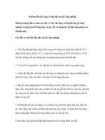
may be made for deficiencies greater than one tenth of an inch. In form
paving, these tolerances are usually accomplished with a machine called a
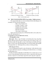
sub-grader which rides on the forms (Figure 2-1). The subgrade may be
trimmed with a conventional grader. In slip form paving, an auto-grade
machine with an automatic grade control sets the grade from a string line.
Figure 2-1. Form Paving Spreader
No equipment or traffic is allowed on the finished subgrade because
distortion of the subgrade may occur if a weak soil condition exists or the
subgrade is overly wet after a rain.
SUBBASE
Subbase is a foundation course that is placed and compacted on a prepared
subgrade. Section 302 lists the materials and construction requirements for
subbase.
INDOT uses two types of subbase in concrete pavements. The most
commonly used is Subbase for PCCP and the other is Dense Graded
Subbase.
Subbase for PCCP consists of 3 in. of an aggregate drainage layer placed
over a 6 in aggregate separation layer. The drainage layer consists of
coarse aggregate size No. 8 in accordance with Section 904.03. The
separation layer consists of coarse aggregate size No. 53 in accordance with
Section 904.03.
Dense Graded Subbase consists of 6 in of coarse aggregate size No. 53 in
accordance with Section 904.03.
The preparation and placement of subbase is required to be in accordance
with the applicable requirements of Section 302. Compaction of the
drainage layer requires two passes with a vibratory roller before trimming
and one pass with a tandem roller after trimming.
After the final trimming and compacting of Subbase for PCCP, depth
determinations are required for each layer. The Technician should take
measurements at a minimum frequency of one depth determination per each
traffic lane for each 500 linear ft of each layer of subbase. The technician
needs to keep a permanent record of all depth checks, including the date,
location, and thickness of all checks. This record needs to be submitted
with the final construction record to verify the quantity of material actually
placed. If deficiencies are found in the thickness, appropriate measures are
required to be taken. If more material is required, the additional material is
mixed with the layer and the layer is re-compacted. Additional depth
determinations are then obtained.
The width of the subbase must also be checked and recorded by the
Technician. The frequency of these width checks should match the depth
check frequency. These checks are required to verify the quantity of
material in cubic yards that were actually placed.
3 Concrete Job Control
Materials
Aggregates
Portland Cement
Fly Ash/GGBFS
Water
CMD Process
Testing Equipment Calibration
Referenced Documents
Safety
Sampling Concrete
Sampling from Concrete Trucks
Sampling from Grade
Sampling from Central Mixed Plant
Testing Concrete
Pressure Method for Air Content
Volumetric Method for Air Content
Unit Weight and Relative Yield
Slump
Making and Curing Test Specimens in the Field
Flexural Strength
Water/Cementitious Ratio
Curing Concrete
Failed Materials
3-1
CHAPTER THREE:
CONCRETE JOB CONTROL
Concrete used in pavements on INDOT contracts must meet the requirements of Section
501 or 502. Concrete used as a base must meet the requirements of Section 305. Patching
concrete must meet the requirements of Section 506. In order to verify that the concrete
meets the applicable specification requirements, the Technician must perform job control
sampling and testing of the freshly mixed and hardened concrete.
Concrete pavements meeting the requirements of Section 501 are referred to as Quality
Control/Quality Assurance Portland Cement Concrete Pavement, or QC/QA PCCP.
Concrete pavements meeting the requirements of Section 502 are simply referred to as
PCCP.
Prior to concrete production, the Technician is required to participate in the trial batch
demonstration, verify that the concrete plant is utilizing Certified Aggregate Producer
Program, CAPP, approved aggregates as well as approved cement, fly ash, and
admixtures. The Technician also determines if all job control testing equipment has been
calibrated and is in good working order. The sampling and testing methods required by
the contract and the frequency of each test in accordance with the Manual of Frequency
for Sampling and Testing should be reviewed. The Manual for Frequency of Sampling
and Testing and approved lists for the various materials used in concrete production can
be found on the INDOT website.
MATERIALS
Paving concrete is basically composed of the following materials (Figure 3-1):
1) Fine aggregate
2) Coarse aggregate
3) Portland cement
4) Water
3-2
Additional materials that may be found in paving concrete are:
1) Fly Ash or Ground Granulated Blast Furnace Slag, GGBFS
2) Water-reducing admixture
3) Air-entraining admixture
Figure 3-1. Concrete Materials
3-3
The proportions of materials vary with different types of concrete. Prior to production of
concrete, the Contractor is responsible for performance of the concrete mix design process,
CMD. The Specifications outline the requirements of the process and additional
information regarding the CMD process is included later in this chapter.
AGGREGATES
As mentioned previously, concrete mixes include two aggregate types. Fine aggregates are
sands, usually meeting No. 23 aggregate gradation requirements. Concrete used in QC/QA
PCCP may use an alternate gradation if identified in the Contractor’s Quality Control Plan,
QCP. Coarse aggregates are larger particles, usually meeting the gradation requirements
for coarse aggregate No. 8. Concrete used in QC/QA PCCP may also use an alternate
coarse aggregate gradation if identified in the QCP. Section 904.02(d) requires that fine
aggregate included in concrete used for base, pavement, and patching to be natural sands.
Section 904.03 includes the classification requirements for coarse aggregate materials. The
proportion of the aggregates is important to the integrity of the concrete and may affect the
ultimate strength and the durability of the pavement. The fine aggregate is required to be
35 to 45% (35 to 50% for QC/QA PCCP) of the combined total weight of the coarse and
fine aggregates (Figure 3-2).
Figure 3-2. Fine Aggregate/Coarse Aggregate Proportions
3-4
PORTLAND CEMENT
There are many different types of cement available for concrete. Only the following five
are discussed:
1) Portland cement, Type I
2) Air-entrained Portland cement, Type I-A
3) Air-entrained Portland-pozzolan cement, Type IP-A
4) High early strength cement, Type III
5) Air-entrained high early strength cement, Type III-A
Under normal conditions, Portland cement, Type I is used in paving concrete. Air-
entrained Portland cement, Type I-A, is cement that has been entrained with air during the
manufacturing process and requires less air-entraining agent to be added to obtain the
required air content. Portland-pozzolan cement, Type IP is similar to Type I, except that
the cement also contains a pozzolan, such as fly ash, to reduce the cost. Air-entrained
Portland-pozzolan cement, Type IP-A is similar to Type I-A, except that this cement also
contains a pozzolan. When Portland cement, Type IP-A is used, fly ash/GGBFS
specifications regarding allowable calendar periods apply. Portland cement, Type III
obtains a high early strength. Portland cement, Type III-A is similar to Type III except
that this cement contains entrained air from the manufacturing process.
Unless otherwise specified, each cubic yard of paving concrete contains 564 lbs or six
bags of cement. In order to verify that the concrete used in pavement meets this
requirement, the Technician will perform a unit weight/relative yield test at the paving site
as soon as the first load begins discharging. The results of this test determine the actual
amount of cement in each cubic yard of concrete. If the cement content is determined to
be high, the aggregate batch weights are required to be increased to lower the total cement
content. If the cement content is too low, the aggregate batch weights are decreased to
increase the cement content. Additional information regarding unit weight/relative yield
testing follows later in this chapter.
FLY ASH/GGBFS
Fly ash is a powdery by-product of coal fired electrical generating plants which has similar
structural properties as cement. GGBFS is a by-product of the steel production process that
is produced in a molten condition in a blast furnace and then cooled by immersing it in
water. The use of fly ash or GGBFS reduces the cost of concrete by reducing the amount
of cement required, but may extend the time needed to achieve the proper strength for
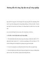
opening the pavement to traffic. When fly ash or GGBFS is included in the concrete mix,
the Technician is required to cast beams (Figure 3-3) in conjunction with each pour. The
flexural strength of these beams is the only factor used to determine the opening of the
pavement to traffic. Additional information related to flexural strength testing can be
found later in this chapter.
3-5
Figure 3-3. Concrete Beam Used for Flexural Testing
The two types of fly ash used in PCCP are Class C and Class F. Class C fly ash has better
structural qualities than Class F and is therefore the preferred type of fly ash. Sections
501.05 and 502.04, limit the times of the year that fly ash or GGBFS may be used.
The minimum cement/fly ash and minimum cement/GGBFS ratios for QC/QA PCCP are
included in Section 501.05. For PCCP, Section 502.04 includes information related to the
maximum cement reduction for fly ash replacement and the GGBFS/cement substitution
ratios for regular paving concrete and high-early strength concrete mixes.
WATER
When water is added to the cement, the setting and curing process begins. In a central-mix
plant this process occurs in the mixing drum, and in a transit mix this process occurs in the
truck mixer. Only clean, potable water shall be used. Contaminated water may contain
materials which are detrimental to the concrete after placement.
After the water is added to the mix for concrete associated with PCC base, QC/QA PCCP,
or PCCP, the concrete is required to be placed within 90 minutes if hauled in truck mixers
or trucks equipped with agitators. If the hauling vehicles have no agitators, this time is
reduced to 30 minutes if the concrete temperature is 90
◦
F or above and 45 minutes for
cooler temperatures. The time the water is added to the concrete is stamped on the ticket
at the concrete plant.
For patching mixtures, the concrete must be placed within 30 minutes of the time that
water is added if hauled in a truck with no agitators. If the truck has agitators or if a truck
mixer is used, the concrete must be placed within 90 minutes of the time that water was
added or within 30 minutes of introduction of calcium chloride solution, whichever is less.
The amount of water added at the plant varies from day to day depending upon the
moisture contents of the fine and coarse aggregates used. If an overnight rain has caused
the stockpiled materials to become wetter than the day before, less water is required to be
added at the plant. Materials exposed to hot, dry conditions for several days require more
water to be added. The mixture is required to contain no more water than is necessary to
produce a concrete that is workable, plastic, and meets the slump requirements; however,
the water-cementitious ratio is required to meet the specification limits at all times.
CMD PROCESS
The CMD process includes two steps. First the Contractor prepares a concrete mix design
submittal, CMDS on a Department provided spreadsheet and sends it to the District
Testing Engineer, DTE. This submittal is made at least 7 calendar days prior to the
performance of a trial batch, if a trial batch is required by Section 501.06. The Technician
will participate in the trial batch by performing side by side tests with Contractor
personnel to verify that the CMDS is capable of meeting all requirements contained in
Section 501.06 and to demonstrate the testing proficiency of Contractor personnel. Upon
successful completion of the trial batch, the Contractor is required to submit
documentation related to the second stage of the CMD process—the concrete mix design
for production, CMDP. This submittal is required at least 3 work days prior to beginning
of the paving operation and is made to the DTE. The Technician’s test results are required
3-6
to accompany the Contractor’s CMDP submittal. Upon approval of the CMDP, the
Contractor may begin production of the concrete for the paving operation. Should the
Contractor’s CMDS not require a trial batch in accordance with Section 501.06, the DTE
will review, process, and return the spreadsheet as an approved CMDP.
Once a CMDP is approved, the Contractor may alter the CMDP in one of the following
fashions:
1) Change in materials as described in Section 501.04(a)
2) Adjustment to materials as described in Section 501.04(b)
3) Other adjustments as described in Section 501.04(c)
When a change in materials is proposed for a concrete mix, a new CMDS reflecting the
material change must be submitted by the Contractor to the DTE for approval. In this
situation, the Contractor may perform a trial batch as described previously to verify the
performance of the new CMDS or use concrete from the first day of production as the trial
batch in accordance with Section 501.04(a). If the first production day is used as the trial
batch, the Technician will coordinate sampling and testing with Contactor personnel to
evaluate the concrete shortly after production begins. If random sampling requires that an
acceptance test is to be performed during this first day of production, the acceptance
testing can be used by the Technician to evaluate the new concrete mix design. If any
Technician’s test result from samples taken during this first day of production indicates a
failure to meet the specification requirements, the Technician must notify the PE/PS as
soon as possible so the paving operation can be suspended. Any pavement constructed
prior to the suspension of the paving operation will be treated as a failed material.
Additional information regarding failed materials can be found later in this chapter.
If the previously approved CMDP is adjusted in accordance with Section 501.04(b), the
Contractor is required to submit information related to the material adjustment to the DTE
for approval. After DTE approval is obtained, a new CMDP is issued and production can
resume. Neither a trial batch nor verification on the first day of production CMDP is
required for an adjusted CMDP. Random acceptance sampling and testing performed by
the Technician is not affected by the Contractor’s use of an adjusted CMDP.
With proper notification to the PE/PS, the Contractor may incorporate other material
adjustments to a CMDP in accordance with Section 501.04(c). Such adjustments are minor
and do not require a new CMDS, nor do they require DTE approval.
It should be noted that the specifications do allow the Contractor to utilize a previously
approved CMDP from another contract. However, changing or adjusting the CMDP will
require DTE approval in accordance with Section 501.04(a) and 501.04(b), respectively.
3-7
TESTING EQUIPMENT CALIBRATION
All concrete job-control testing equipment is required to be calibrated at the proper
frequency. The calibration process includes sieves, electronic scales, air test equipment,
slump equipment, thermometers, and equipment for determination of the unit weight of
concrete. Flexural strength testing machines and compressive strength testing machines
are required to be calibrated annually and after being moved. INDOT compressive
strength testing machines are calibrated by companies under contract to INDOT.
Compressive strength and flexural strength testing machines used by the Contractor on
contracts including QC/QA PCCP pay items are required to also be calibrated. The
calibrations of the equipment at these locations are the responsibility of the Contractor or
the Supplier. Calibration documentation should be produced by the Contractor or Supplier
for each testing machine and reviewed by District Testing personnel prior to the use of the
testing machine for testing concrete for INDOT work.
The following documents should be reviewed by the Technician for additional information related to testing
equipment calibration:
1) AASHTO T 152 - Air Meter and Unit Weight Containers
2) ITM 902 – Sieves
3) ITM 903 – Ovens
4) ITM 910 – Electronic Balances
5) ITM 911 - Slump Cones
REFENCED DOCUMENTS
ITM and AASHTO test methods are used for concrete job control. INDOT Specifications
contain several exceptions to the AASHTO test methods. If there are INDOT exceptions
to AASHTO, then INDOT Specifications take precedence over AASHTO test methods.
The AASHTO test methods and Section 505 should be reviewed for any corresponding
exceptions. The Special Provisions of a contract may have additional or different
exceptions than those found in Section 505. All three documents should be reviewed by
the Technician prior to production of concrete on the contract.
SAFETY
Prolonged exposure of skin and tissue to concrete may be harmful. Therefore, the Technician
should wear plastic or latex gloves while sampling and testing of concrete. Protective eye
wear is also recommended because concrete may splatter during testing.
SAMPLING CONCRETE
AASHTO T 141 is the test method required for sampling freshly mixed concrete. An
exception to this test method that INDOT allows is that the entire sample may be obtained
from one portion of the load. Obtaining a representative sample of the concrete to be
tested is important for assuring an accurate determination of the concrete properties. If
any sample is improperly taken, then the test results are not acceptable. Representative
material is important for samples taken by the Contractor for job control, samples taken by
independent testing companies, and samples that are used to appeal INDOT test results.
Although AASHTO T 141 does not define the sampling container, other test methods are
very specific on acceptable types of containers. A wheelbarrow meets the requirements of
3-8
all the AASHTO test methods used for acceptance testing of concrete by INDOT and
therefore is generally used as the sampling and mixing container.
INDOT test samples are obtained at the point of placement whenever possible. QC/QA
PCCP and PCCP samples are taken on the grade after the material has been placed by a
material transfer machine, but before the concrete paver has distributed the mixture. When
samples are taken in close proximity to operating equipment, communication between all
personnel associated with obtaining the sample and equipment operators must be clear at
all times.
INDOT allows two types of freshly mixed plastic concrete samples:
1) A composite sample consisting of two or more increments taken from
the batch and mixed together in the sampling receptacle
2) One large increment taken from one portion of the load
The type of sample required is determined by the sampling technique method.
Regardless of where the sample is obtained, no more than 15 minutes should elapse
between obtaining the first and final portions of the sample. Also, no sample is obtained
before approximately 10 % of the load has been discharged or after approximately 90 % of
the load has been discharged.
3-9
SAMPLING FROM CONCRETE TRUCKS
When sampling from a revolving drum truck mixer (transit-mix truck) or an agitator truck,
the sample may be obtained by directing the chute to a wheelbarrow (Figure 3-4) or to a
receptacle on the ground near the testing site. The sample is not obtained from the chute of
the truck or from the discharge stream of the concrete when filling the receptacle.
F
i
g
u
r
e
3-4. Sampling from Truck
SAMPLING FROM GRADE
When sampled from the grade (Figure 3-5), the sample is taken before any machinery
comes in contact with the concrete.
When the sample is obtained from a pile on the grade or the ground near the testing site,
samples are taken from five different portions of the pile. The sample should not be
contaminated with the base material.
After obtaining the concrete sample, all portions of the concrete are mixed together with a
shovel the minimum amount necessary to obtain proper uniformity.
3-10
Figure 3-5. Sampling from Grade
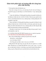
SAMPLING FROM CENTRAL MIXED PLANTS
When a concrete sample is tested at a central mixed plant, such as would be required for a trial
batch, the procedure for sampling the concrete is to have the plant discharge a load directly
into the bucket of a loader (Figure 3-6).
F
i
g
u
r
e
3-6. Loading a Bucket
3-11
The loader bucket is cleaned ahead of time to minimize any possible contamination of the
sample. The loader then transports the material to the testing location where the concrete is
sampled (Figure 3-7).
Figure 3-7. Sampling from a Loader
After sampling the concrete, all portions are thoroughly mixed together with a shovel the
amount necessary to obtain proper uniformity (Figure 3-8).
Figure 3-8. Mixing Sample