Tài liệu Lab Exercise 1: VLAN, Trunk, and EtherChannel Configuration pptx
Bạn đang xem bản rút gọn của tài liệu. Xem và tải ngay bản đầy đủ của tài liệu tại đây (26.74 KB, 4 trang )
CertificationZone Page 1 of 4
/?Issue=36&IssueDate=05-01-2001&CP= 11/06/01
Date of Issue: 05-01-2001
Lab Exercise 1: VLAN, Trunk, and
EtherChannel Configuration
by Dan Farkas
Introduction
Equipment
Initial Configuration
Part 1: VLANs and Trunks
Goals
Task List
Solutions - Part 1
Answers
Configurations
Part 2: EtherChannel
Goals
Task List
Solutions - Part 2
Answers
Configurations
Introduction
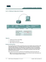
This lab has two parts. The first part requires configuring links as trunks and creating VLANs. In the second part, the
links are configured as Fast EtherChannel.
Equipment
• Two Catalyst 5xxx or 6xxx switches with Fast EtherChannel capable line cards
• Three PCs with NIC cards
• One Cisco router with an Ethernet or Fast Ethernet interface
Initial Configuration
CertificationZone Page 2 of 4
/?Issue=36&IssueDate=05-01-2001&CP= 11/06/01
VTP Domain: lab
VLAN 1 name: vlan1
VLAN 2 name: vlan2
VLAN 3 name: vlan3
Part 1: VLANs and Trunks
Goals
Switch A and Switch B are directly connected. First, configure the links connecting them as ISL trunks. Then
configure Switch A as a VTP server and Switch B as a VTP client. Create VLANs 2 and 3 on Switch A. PC-1 and PC-
2 will connect to VLAN 2, and PC-3 connects to VLAN 3. The router will also connect to the VLAN 3 port. The
switches remain in VLAN 1. All devices in similar VLANs should be able to ping one another, but there should be no
inter-VLAN connectivity.
Task List
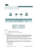
1. Configure each PC with the appropriate IP address and subnet mask
2. Configure the router Ethernet or Fast Ethernet interface with the appropriate IP address and subnet mask.
3. On Switch B
a. Use the set interface sc0 command to set the appropriate IP address and subnet mask.
b. Use the set vtp command to set the VTP domain and mode.
c. Place the ports connected to PC-2 and PC-3 in the appropriate VLANs. Did this work? Why or why
not?
4. On Switch A
a. Use the set interface sc0 command to set the appropriate IP address and subnet mask.
b. Use the set vtp command to set the VTP domain and mode.
c. Switch B is set in the default mode for trunk negotiation. What command should you enter to make the
links trunks? Enter that command for the ports connected to B.
d. Create VLANs 2 and 3.
e. Place the ports connected to PC-1 and the router in the appropriate VLANs. Did this work? Why or
why not?
Device IP Addresses
Switch A 10.1.1.1/24
Switch B 10.1.1.2/24
PC-1 10.2.1.1/24
PC-2 10.2.1.2/24
PC-3 10.3.1.2/24
Router 10.3.1.1/24
CertificationZone Page 3 of 4
/?Issue=36&IssueDate=05-01-2001&CP= 11/06/01
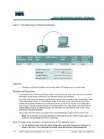
5. On Switch B
a. Place the ports connected to PC-2 and PC-3 in the appropriate VLANs. Did this work? Why or why
not?
6. Ping between devices. Do intra-VLAN pings work? If not, something is not right in your configuration. Do inter-
VLAN pings work? Why or why not?
Solutions - Part 1
Answers
3) The configuration command should fail due to the fact that the VLANs have not been defined on Switch B. VLANs
must be defined before ports can be placed in a VLAN. Since Switch B is a VTP client, it will not allow the creation of
VLANs
4c) set trunk desirable or set trunk on would be needed since Switch B is defaulting to set trunk auto.
4e) Yes, this is the normal configuration order, so the commands should work.
5) Yes, since Switch B learned about the VLANs via VTP from Switch A, Switch B can now place ports into VLANs 2
and 3
6) Intra-VLAN pings should succeed. Inter-VLAN pings should fail because no inter-VLAN routing has been
configured.
Configurations
{Note: x/y represent slot and port numbers, which will vary depending on equipment used.}
SwitchA(enable)set int sc0 10.1.1.1 255.255.255.0
SwitchA(enable)set vtp domain lab
SwitchA(enable)set trunk x1/y1 desirable
SwitchA(enable)set trunk x1/y2 desirable
SwitchA(enable)set vlan 2 name vlan2
SwitchA(enable)set vlan 3 name vlan3
SwitchA(enable)set vlan 2 x1/y3
SwitchA(enable)set vlan 3 x1/y4
SwitchB(enable)set int sc0 10.1.1.2 255.255.255.0
SwitchB(enable)set vtp domain lab mode client
SwitchB(enable)set vlan 2 x2/y5
SwitchB(enable)set vlan 3 x2/y6
Router(config)#int fa x3/y7
Router(config-if)#ip address 10.3.1.1 255.255.255.0
Part 2: EtherChannel
Goals
Configure the links between Switch A and Switch B to be a Fast EtherChannel connection. The pings should still work
(and not work) as in Part 1.
Task List
1. On Switch A and Switch B:
a. Use the set port channel command to set up EtherChannel
CertificationZone Page 4 of 4
/?Issue=36&IssueDate=05-01-2001&CP= 11/06/01
b. Use the show port channel command. Note, which ports are channeling?
2. Ping between devices. Do intra-VLAN pings work? If not, something is not right in your configuration. Do inter-
VLAN pings work? Why or why not?
Solutions - Part 2
Answers
{Note: the port numbers should reflect the ones you've actually used}
1b)
SwitchA(enable) show port channel
Port Status Channel Channel Neighbor Neighbor
mode status device port
2/1 connected on channel WS-C5000 000001234 2/5
2/2 connected on channel WS-C5000 000001234 2/6
2) Intra-VLAN pings should still succeed. Inter-VLAN pings should still fail because no inter-VLAN routing has been
configured.
Configurations
{Note: the port selection must follow proper EtherChannel rules as discussed in the Tutorial.}
SwitchA(enable)set port channel x1/y1-y2
[IE-LANS2-LS1-F04]
[2001-04-20-02]
Copyright © 2001 Genium Publishing Corporation