Tài liệu Lab 4.3.2 Configuring Legacy DDR docx
Bạn đang xem bản rút gọn của tài liệu. Xem và tải ngay bản đầy đủ của tài liệu tại đây (194.39 KB, 8 trang )
1 - 8 CCNA 4: WAN Technologies v 3.0 - Lab 4.3.2 Copyright 2003, Cisco Systems, Inc.
Lab 4.3.2 Configuring Legacy DDR
Objective
• Configure an ISDN router to make a Legacy dial-on-demand routing (DDR) call to another ISDN
capable router.
• When the DDR connection is successfully made, augment the configuration to specify that only
http traffic will bring up the link.
Background/Preparation
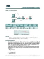
In this lab, 2 ISDN routers are required. If ISDN routers are not available, review the lab to become
familiar with the process. An Adtran Atlas550 ISDN emulator is used to simulate the switch/ISDN
cloud.
Cable a network similar to the one in the diagram above. Any router that meets the interface
requirements displayed on the above diagram may be used. This includes the following and any of
their possible combinations:
• 800 series routers
• 1600 series routers
• 1700 series routers
• 2500 series routers
2 - 8 CCNA 4: WAN Technologies v 3.0 - Lab 4.3.2 Copyright 2003, Cisco Systems, Inc.
• 2600 series routers
Please refer to the chart at the end of the lab to correctly identify the interface identifiers to be used
based on the equipment in the lab. The configuration output used in this lab is produced from 1721
series routers. Any other router used may produce slightly different output. Conduct the following
steps on each router unless specifically instructed otherwise.
Start a HyperTerminal session as.
Note: Refer to the erase and reload instructions at the end of this lab. Perform those steps on all
routers in this lab assignment before continuing.
Step 1 Configure the routers
Configure all of the following according to the chart:
• The hostname
• The console
• The virtual terminal
• The enable passwords
If there is a problem completing this, refer to the Network Address Translation (NAT) configuration
lab.
Step 2 Define switch type and spid numbers
The switch type and spid numbers need to be specified on the routers.
Router(config)#hostname Tokyo
Tokyo(config)#enable secret class
Tokyo(config)#isdn switch-type basic-ni
Tokyo(config)#interface fastethernet 0
Tokyo(config-if)#ip address 192.168.1.1 255.255.255.0
Tokyo(config-if)#no shutdown
Tokyo(config-if)#exit
Tokyo(config)#interface bri 0
Tokyo(config-if)#isdn spid1 51055510000001 5551000
Tokyo(config-if)#isdn spid2 51055510010001 5551001
Tokyo(config-if)#no shutdown
Router(config)# hostname Moscow
Moscow(config)# enable secret class
Moscow(config)# isdn switch-type basic-ni
Moscow(config)# interface fastethernet 0
Moscow(config-if)#ip address 192.168.2.1 255.255.255.0
Moscow(config-if)#no shutdown
Moscow(config-if)#exit
Moscow(config)# interface bri 0
Moscow(config-if)#isdn spid1 51055520000001 5552000
Moscow(config-if)#isdn spid2 51055520010001 5552001
Moscow(config-if)#no shutdown
3 - 8 CCNA 4: WAN Technologies v 3.0 - Lab 4.3.2 Copyright 2003, Cisco Systems, Inc.
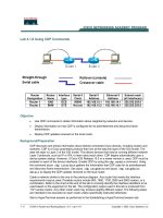
Step 3 Defining static routes for DDR
a. Use static and default routes instead of dynamic routing, in order to reduce the cost of the dialup
connection. To configure a static route, the network address of the network to be reached must
be known. The IP address of the next router on the path to this destination must be known as
well.
Moscow#configure terminal
Moscow(config)# ip route 192.168.1.0 255.255.255.0 192.168.3.1
Tokyo#configure terminal
Tokyo(config)# ip route 0.0.0.0 0.0.0.0 192.168.3.2
b. Perform a show IP route to verify routes exist.
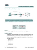
Step 4 Specifying interesting traffic for DDR
Specify the traffic that will cause the DDR interface to dialup the remote router. For the moment,
declare that all IP traffic is interesting. This is done using the dialer-list command:
Tokyo#configure terminal
Tokyo(config)#dialer-list 1 protocol ip permit
Tokyo(config)#interface bri 0
Tokyo(config-if)#dialer-group 1
Tokyo(config-if)#end
Step 5 Configuring DDR dialer information
a. Configure the correct dialer information so that the dialer profile and dialer interface function
correctly. This includes all of the following:
• IP address information
• PPP configuration
• Name
• Passwords
• Dial number
Tokyo#configure terminal
Tokyo(config)#interface bri 0
Tokyo(config-if)#ip address 192.168.3.1 255.255.255.0
b. Configure the PPP information:
Tokyo#configure terminal
Tokyo(config)#username Moscow password class
Tokyo(config)#interface bri 0
Tokyo(config-if)#encapsulation ppp
Tokyo(config-if)#ppp authentication chap
4 - 8 CCNA 4: WAN Technologies v 3.0 - Lab 4.3.2 Copyright 2003, Cisco Systems, Inc.
c. Configure the dial information:
Tokyo#configure terminal
Tokyo(config)#interface bri 0
Tokyo(config-if)#dialer idle-timeout 120
Tokyo(config-if)#dialer map ip 192.168.3.2 name Moscow 5552000
Step 6 Configuring DDR Dialer Information
Moscow#configure terminal
Moscow(config)#dialer-list 1 protocol ip permit
Moscow(config)#username Tokyo password class
Moscow(config)#interface bri 0
Moscow(config-if)#ip address 192.168.3.2 255.255.255.0
Moscow(config-if)#dialer-group 1
Moscow(config-if)#encapsulation ppp
Moscow(config-if)#ppp authentication chap
Moscow(config-if)#dialer idle-timeout 120
Moscow(config-if)#dialer map ip 192.168.3.1 name Tokyo 5551000
Step 7 Configure dialer information
a. The dial information must specify the remote name of the remote router in the dialer profile. It
must also specify the dial string, or phone number, to use to contact the remote device.
b. To configure the dial information on Tokyo, use the following:
Tokyo(config)#interface dialer 1
Tokyo(config-if)#dialer remote-name Moscow
Tokyo(config-if)#dialer string 5552000
Tokyo(config-if)#dialer string 5552001
c. To configure the dial information on Moscow, use the following:
Moscow(config-if)#interface dialer 0
Moscow(config-if)#dialer remote-name Tokyo
Moscow(config-if)#dialer string 5551000
Moscow(config-if)#dialer string 5551001
Use the same commands, as Moscow, to configure the Sydney router.
Step 8 Associate dialer profiles
a. To associate the dialer profiles with real dialer interfaces create a dialer pool putting the
interfaces and the associated profiles in a common pool.
b. On Tokyo, the commands syntax is as follows:
Tokyo(config-if)#interface bri 0
Tokyo(config-if)#dialer pool-member 1
Tokyo(config-if)#interface dialer 1
Tokyo(config-if)#dialer pool 1
5 - 8 CCNA 4: WAN Technologies v 3.0 - Lab 4.3.2 Copyright 2003, Cisco Systems, Inc.
c. On Moscow, the commands syntax is the following:
Moscow(config-if)#interface bri 0
Moscow(config-if)#dialer pool-member 1
Moscow(config-if)#interface dialer 0
Moscow(config-if)#dialer pool 1
d. Use the same commands to configure the Sydney router.
Step 9 Configure dialer timeouts
a. Configure a dialer idle-timeout of 60 seconds for each of the dialer interfaces:
Tokyo(config)# interface dialer 1
Tokyo(config-if)#dialer idle-timeout 60
Tokyo(config-if)#interface dialer 2
Tokyo(config-if)#dialer idle-timeout 60
b. Repeat these commands on Moscow and Sydney.
Step 10 View the Tokyo router configuration
a. To view the configuration, use the show running-config command:
Tokyo#show running-config
b. What authentication is being used?
__________________________________________________________________________
c. What are the dialer strings on the Tokyo router?
__________________________________________________________________________
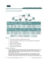
Step 11 Verifying the DDR Configuration
a. Now, generate some interesting traffic across the DDR link from both remote routers, Moscow
and Tokyo, to verify that connections are made correctly and the dialer profiles are functioning:
Tokyo#ping 192.168.1.1
b. Were the pings successful?
__________________________________________________________________________
c. If not troubleshoot the router configuration.
d. Use the show dialer command to show us the reason for the call. This information is shown
for each channel.
Tokyo#show dialer
e. Which dialer strings are associated with Dialer1?
__________________________________
f. What is the last status for dial string 5553000 in the Dialer2 readout?
____________________
6 - 8 CCNA 4: WAN Technologies v 3.0 - Lab 4.3.2 Copyright 2003, Cisco Systems, Inc.
g. Use the show interface command and note that the output shows that the interface is
spoofing. This provides a mechanism for the interface to simulate an active state for internal
processes, such as routing, on the router. The show interface command can also be used to
display information about the B channel:
Tokyo#show interface bri 0
Upon completion of the previous steps, finish the lab by doing the following:
• Logoff by typing exit
• Turn the router off
• Remove and store the cables and adapter
7 - 8 CCNA 4: WAN Technologies v 3.0 - Lab 4.3.2 Copyright 2003, Cisco Systems, Inc.
Erasing and reloading the router
Enter into the privileged exec mode by typing enable.
If prompted for a password, enter class (if that does not work, ask the instructor).
Router>enable
At the privileged exec mode enter the command erase startup-config.
Router#erase startup-config
The responding line prompt will be:
Erasing the nvram filesystem will remove all files! Continue? [confirm]
Press Enter to confirm.
The response should be:
Erase of nvram: complete
Now at the privileged exec mode enter the command reload.
Router(config)#reload
The responding line prompt will be:
System configuration has been modified. Save? [yes/no]:
Type n and then Enter.
The responding line prompt will be:
Proceed with reload? [confirm]
Press Enter to confirm.
In the first line of the response will be:
Reload requested by console.
After the router has reloaded the line prompt will be:
Would you like to enter the initial configuration dialog? [yes/no]:
Type n and then Enter.
The responding line prompt will be:
Press RETURN to get started!
Press Enter.
Now the router is ready for the assigned lab to be performed.
8 - 8 CCNA 4: WAN Technologies v 3.0 - Lab 4.3.2 Copyright 2003, Cisco Systems, Inc.
Router Interface Summary
Router
Model
Ethernet
Interface #1
Ethernet
Interface #2
Serial
Interface #1
Serial
Interface #2
800 (806) Ethernet 0 (E0) Ethernet 1 (E1)
1600 Ethernet 0 (E0) Ethernet 1 (E1) Serial 0 (S0) Serial 1 (S1)
1700 FastEthernet 0 (FA0) FastEthernet 1 (FA1) Serial 0 (S0) Serial 1 (S1)
2500 Ethernet 0 (E0) Ethernet 1 (E1) Serial 0 (S0) Serial 1 (S1)
2600 FastEthernet 0/0 (FA0/0) FastEthernet 0/1 (FA0/1) Serial 0/0 (S0/0) Serial 0/1 (S0/1)
In order to find out exactly how the router is configured, look at the interfaces. This will identify what type and how
many interfaces the router has. There is no way to effectively list all of the combinations of configurations for each
router class. What is provided are the identifiers for the possible combinations of interfaces in the device. This
interface chart does not include any other type of interface even though a specific router may contain one. An
example of this might be an ISDN BRI interface. The string in parenthesis is the legal abbreviation that can be
used in IOS command to represent the interface.