Tài liệu Microprocessor Interfacing Techniques Lab VIEW Tutorial Part 6 doc
Bạn đang xem bản rút gọn của tài liệu. Xem và tải ngay bản đầy đủ của tài liệu tại đây (65.51 KB, 3 trang )
PHY 406 - Microprocessor Interfacing Techniques
© James R. Drummond - September 1996 28
PHY 406 - Microprocessor Interfacing Techniques
LabVIEW Tutorial - Part VI
Error Handling
Handling Errors
Before I show you how to connect an error message handler into the system it is
important to realise that an error handler has to do something with the error or it will happen
again. In this case if we find an error (array dimension <1) then unless we either increase the
array dimension or abort the program, it will immediately happen again, and again, and again
It is therefore important to always think about what to do about an error as well as report it. In
addition if we are going to stop the program, we must ensure that the error is reported before the
program is stopped - ie the data flow must be through the error handler.
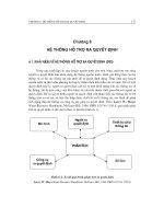
The standard deviation box has an error output for exactly this
purpose. It is an integer whose value is 0 in normal operation and non-
zero if there is an error. A simple error handler therefore would stop the
program if the error output was non-zero. Or phrased another way: The
program continues if the run switch is on (true) and the error output is
zero. The logic looks like this:
This will certainly stop the VI if the error output becomes non-
zero, but it won’t tell you why it’s stopping! What we need is an indicator
to tell us what the error is. If you actually put an indicator on the line it will indicate a number
(-20003 to be precise) but that still doesn’t tell me what the error is. I need that error to be
interpreted in plain Canadian. This is the job of the (simple) error handler. Find that on
functions>>Time & Dialog (bottom left corner) and place it on the diagram.
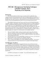
This function is quite
complex as you can see from the
help screen (Ctrl-H remember!).
The only two leads you need at the
moment are the “error code” input
and the “code out”. Remember
what I said about dataflow. The
error handler must be traversed
before the VI si stopped. We
therefore wire the error output of
the standard deviation analysis to
the input and the output to the
comparator and abort logic. This
ensures the proper dataflow.
PHY 406 - Microprocessor Interfacing Techniques
© James R. Drummond - September 1996 29
Now when you run the VI, try using 0 as the number of elements to average and see what
happens. You should get a nice error box which tells you that “Error -20003 has occured at an
unknown location and the probable cause is that the number of samples for analysis is less than
one.
A final piece of customisation is to add a text string to tell the system where the error
occurred - the error source. After all, in a real VI there might be a number of places that this
error could occur and you would like to know which one it really is. You can resolve this by
adding a “string” constant for the error source. String constants are exactly what they seem you
can find them under functions>>string>>string constant or you can use the wiring tool and the
pop-up menu to create a string constant input - you’ll need a steady hand for that, things are
getting tight in that area! In both cases add an appropriate string to explain wher the error is
coming from and the box will reflect that text. Notice the new colour for the string wiring.
Summary
The action taken after an error should make sure that the system does not loop on the
error - appropriate action may be an abort
The dataflow must go through the error handler before the error recovery action is taken
Exercise
Under Advanced there is a Stop function. Modify your VI to use it. Is this a good idea?
What are the pros and cons of Stop vs other means of stopping the VI?
Decision, Decisions!
One thing that we often need to do is to take a different action depending on a decision.
“If the number is negative, then don’t take the square root” is a reasonable example and one
which will avoid an error if we cope with it properly. In LabVIEW we can use a case construct
to take care of this. A case construct consists of a number of overlaid panels each corresponding
to a particular value of the input variable. The simplest case is a true/false decision which can be
implemented with a boolean variable, more complex cases involve more states and use an integer
control variable.
Case constructs must all have the same number of inputs and outputs. All outputs must
be driven on all panels of the construct, inputs may be used or ignored at will.
A simple case construct can be made if we
try to find the roots of a quadratic equation with
coefficients a,b and c - we need to account for
imaginary roots. Here is the VI I put together for
that. You should try and re-create it. The Case
structure is under Structures.
PHY 406 - Microprocessor Interfacing Techniques
© James R. Drummond - September 1996 30
The other panel of the Case structure simply palces a zero in
each of the outputs. Remember that every output must be driven on
every pane - no exceptions.
Here is the other pane of the Case structure. Notice that the
unwanted inputs are ignored.
Summary
Case structures allow programs to take different paths depending upon the conditions.
All panels of a case structure have the same number of inputs and outputs.
Unused inputs can be ignored
All outputs must be driven.
Exercise
Try writing aVI to compute sin(x), cos(x) or tan(x) depending upon an input control (if
you get really good try using a “text ring” control). Your program should also worry about the
legality of input.