Tài liệu DSP Builder Reference Manual ppt
Bạn đang xem bản rút gọn của tài liệu. Xem và tải ngay bản đầy đủ của tài liệu tại đây (423.74 KB, 30 trang )
101 Innovation Drive
San Jose, CA 95134
www.altera.com
DSP Builder
Reference Manual
Software Version: 9.0
Document Date: March 2009
Copyright © 2009 Altera Corporation. All rights reserved. Altera, The Programmable Solutions Company, the stylized Altera logo, specific device designations, and all other
words and logos that are identified as trademarks and/or service marks are, unless noted otherwise, the trademarks and service marks of Altera Corporation in the U.S. and other
countries. All other product or service names are the property of their respective holders. Altera products are protected under numerous U.S. and foreign patents and pending ap-
plications, maskwork rights, and copyrights. Altera warrants performance of its semiconductor products to current specifications in accordance with Altera's standard warranty,
but reserves the right to make changes to any products and services at any time without notice. Altera assumes no responsibility or liability arising out of the application or use of
any information, product, or service described herein except as expressly agreed to in writing by Altera Corporation. Altera customers are advised to obtain the latest version of
device specifications before relying on any published information and before placing orders for products or services
.
MNL-DSPBLDR-9.0
© March 2009 Altera Corporation DSP Builder Reference Manual
Contents
Chapter 1. AltLab Library
BP (Bus Probe) . . . . . . . . . . . . . . . . . . . . . . . . . . . . . . . . . . . . . . . . . . . . . . . . . . . . . . . . . . . . . . . . . . . . . . . . . 1–2
Clock . . . . . . . . . . . . . . . . . . . . . . . . . . . . . . . . . . . . . . . . . . . . . . . . . . . . . . . . . . . . . . . . . . . . . . . . . . . . . . . . . 1–2
Clock_Derived . . . . . . . . . . . . . . . . . . . . . . . . . . . . . . . . . . . . . . . . . . . . . . . . . . . . . . . . . . . . . . . . . . . . . . . . . 1–3
Display Pipeline Depth . . . . . . . . . . . . . . . . . . . . . . . . . . . . . . . . . . . . . . . . . . . . . . . . . . . . . . . . . . . . . . . . . 1–4
HDL Entity . . . . . . . . . . . . . . . . . . . . . . . . . . . . . . . . . . . . . . . . . . . . . . . . . . . . . . . . . . . . . . . . . . . . . . . . . . . . 1–4
HDL Import . . . . . . . . . . . . . . . . . . . . . . . . . . . . . . . . . . . . . . . . . . . . . . . . . . . . . . . . . . . . . . . . . . . . . . . . . . . 1–5
HDL Input . . . . . . . . . . . . . . . . . . . . . . . . . . . . . . . . . . . . . . . . . . . . . . . . . . . . . . . . . . . . . . . . . . . . . . . . . . . . 1–7
HDL Output . . . . . . . . . . . . . . . . . . . . . . . . . . . . . . . . . . . . . . . . . . . . . . . . . . . . . . . . . . . . . . . . . . . . . . . . . . . 1–8
HIL (Hardware in the Loop) . . . . . . . . . . . . . . . . . . . . . . . . . . . . . . . . . . . . . . . . . . . . . . . . . . . . . . . . . . . . . 1–9
Quartus II Global Project Assignment . . . . . . . . . . . . . . . . . . . . . . . . . . . . . . . . . . . . . . . . . . . . . . . . . . . . 1–11
Quartus II Pinout Assignments . . . . . . . . . . . . . . . . . . . . . . . . . . . . . . . . . . . . . . . . . . . . . . . . . . . . . . . . . 1–11
Resource Usage . . . . . . . . . . . . . . . . . . . . . . . . . . . . . . . . . . . . . . . . . . . . . . . . . . . . . . . . . . . . . . . . . . . . . . . 1–12
Signal Compiler . . . . . . . . . . . . . . . . . . . . . . . . . . . . . . . . . . . . . . . . . . . . . . . . . . . . . . . . . . . . . . . . . . . . . . . 1–13
SignalTap II Logic Analyzer . . . . . . . . . . . . . . . . . . . . . . . . . . . . . . . . . . . . . . . . . . . . . . . . . . . . . . . . . . . . 1–14
SignalTap II Node . . . . . . . . . . . . . . . . . . . . . . . . . . . . . . . . . . . . . . . . . . . . . . . . . . . . . . . . . . . . . . . . . . . . . 1–15
Simulation Accelerator . . . . . . . . . . . . . . . . . . . . . . . . . . . . . . . . . . . . . . . . . . . . . . . . . . . . . . . . . . . . . . . . . 1–15
Subsystem Builder . . . . . . . . . . . . . . . . . . . . . . . . . . . . . . . . . . . . . . . . . . . . . . . . . . . . . . . . . . . . . . . . . . . . 1–16
TestBench . . . . . . . . . . . . . . . . . . . . . . . . . . . . . . . . . . . . . . . . . . . . . . . . . . . . . . . . . . . . . . . . . . . . . . . . . . . . 1–17
VCD Sink . . . . . . . . . . . . . . . . . . . . . . . . . . . . . . . . . . . . . . . . . . . . . . . . . . . . . . . . . . . . . . . . . . . . . . . . . . . . 1–18
Chapter 2. Arithmetic Library
Barrel Shifter . . . . . . . . . . . . . . . . . . . . . . . . . . . . . . . . . . . . . . . . . . . . . . . . . . . . . . . . . . . . . . . . . . . . . . . . . . 2–2
Bit Level Sum of Products . . . . . . . . . . . . . . . . . . . . . . . . . . . . . . . . . . . . . . . . . . . . . . . . . . . . . . . . . . . . . . . 2–3
Comparator . . . . . . . . . . . . . . . . . . . . . . . . . . . . . . . . . . . . . . . . . . . . . . . . . . . . . . . . . . . . . . . . . . . . . . . . . . . 2–5
Counter . . . . . . . . . . . . . . . . . . . . . . . . . . . . . . . . . . . . . . . . . . . . . . . . . . . . . . . . . . . . . . . . . . . . . . . . . . . . . . . 2–6
Differentiator . . . . . . . . . . . . . . . . . . . . . . . . . . . . . . . . . . . . . . . . . . . . . . . . . . . . . . . . . . . . . . . . . . . . . . . . . . 2–8
Divider . . . . . . . . . . . . . . . . . . . . . . . . . . . . . . . . . . . . . . . . . . . . . . . . . . . . . . . . . . . . . . . . . . . . . . . . . . . . . . . 2–9
DSP . . . . . . . . . . . . . . . . . . . . . . . . . . . . . . . . . . . . . . . . . . . . . . . . . . . . . . . . . . . . . . . . . . . . . . . . . . . . . . . . . 2–10
Gain . . . . . . . . . . . . . . . . . . . . . . . . . . . . . . . . . . . . . . . . . . . . . . . . . . . . . . . . . . . . . . . . . . . . . . . . . . . . . . . . . 2–15
Increment Decrement . . . . . . . . . . . . . . . . . . . . . . . . . . . . . . . . . . . . . . . . . . . . . . . . . . . . . . . . . . . . . . . . . . 2–17
Integrator . . . . . . . . . . . . . . . . . . . . . . . . . . . . . . . . . . . . . . . . . . . . . . . . . . . . . . . . . . . . . . . . . . . . . . . . . . . . 2–19
Magnitude . . . . . . . . . . . . . . . . . . . . . . . . . . . . . . . . . . . . . . . . . . . . . . . . . . . . . . . . . . . . . . . . . . . . . . . . . . . 2–21
Multiplier . . . . . . . . . . . . . . . . . . . . . . . . . . . . . . . . . . . . . . . . . . . . . . . . . . . . . . . . . . . . . . . . . . . . . . . . . . . . 2–21
Multiply Accumulate . . . . . . . . . . . . . . . . . . . . . . . . . . . . . . . . . . . . . . . . . . . . . . . . . . . . . . . . . . . . . . . . . . 2–24
Multiply Add . . . . . . . . . . . . . . . . . . . . . . . . . . . . . . . . . . . . . . . . . . . . . . . . . . . . . . . . . . . . . . . . . . . . . . . . . 2–26
Parallel Adder Subtractor . . . . . . . . . . . . . . . . . . . . . . . . . . . . . . . . . . . . . . . . . . . . . . . . . . . . . . . . . . . . . . 2–28
Pipelined Adder . . . . . . . . . . . . . . . . . . . . . . . . . . . . . . . . . . . . . . . . . . . . . . . . . . . . . . . . . . . . . . . . . . . . . . 2–30
Product . . . . . . . . . . . . . . . . . . . . . . . . . . . . . . . . . . . . . . . . . . . . . . . . . . . . . . . . . . . . . . . . . . . . . . . . . . . . . . 2–31
SOP Tap . . . . . . . . . . . . . . . . . . . . . . . . . . . . . . . . . . . . . . . . . . . . . . . . . . . . . . . . . . . . . . . . . . . . . . . . . . . . . 2–34
Square Root . . . . . . . . . . . . . . . . . . . . . . . . . . . . . . . . . . . . . . . . . . . . . . . . . . . . . . . . . . . . . . . . . . . . . . . . . . 2–35
Sum of Products . . . . . . . . . . . . . . . . . . . . . . . . . . . . . . . . . . . . . . . . . . . . . . . . . . . . . . . . . . . . . . . . . . . . . . 2–37
Chapter 3. Complex Type Library
Butterfly . . . . . . . . . . . . . . . . . . . . . . . . . . . . . . . . . . . . . . . . . . . . . . . . . . . . . . . . . . . . . . . . . . . . . . . . . . . . . . 3–2
Complex AddSub . . . . . . . . . . . . . . . . . . . . . . . . . . . . . . . . . . . . . . . . . . . . . . . . . . . . . . . . . . . . . . . . . . . . . . 3–4
Complex Conjugate . . . . . . . . . . . . . . . . . . . . . . . . . . . . . . . . . . . . . . . . . . . . . . . . . . . . . . . . . . . . . . . . . . . . 3–6
Complex Constant . . . . . . . . . . . . . . . . . . . . . . . . . . . . . . . . . . . . . . . . . . . . . . . . . . . . . . . . . . . . . . . . . . . . . 3–8
iv Contents
DSP Builder Reference Manual © March 2009 Altera Corporation
Complex Delay . . . . . . . . . . . . . . . . . . . . . . . . . . . . . . . . . . . . . . . . . . . . . . . . . . . . . . . . . . . . . . . . . . . . . . . . 3–9
Complex Multiplexer . . . . . . . . . . . . . . . . . . . . . . . . . . . . . . . . . . . . . . . . . . . . . . . . . . . . . . . . . . . . . . . . . . 3–10
Complex Product . . . . . . . . . . . . . . . . . . . . . . . . . . . . . . . . . . . . . . . . . . . . . . . . . . . . . . . . . . . . . . . . . . . . . 3–11
Complex to Real-Imag . . . . . . . . . . . . . . . . . . . . . . . . . . . . . . . . . . . . . . . . . . . . . . . . . . . . . . . . . . . . . . . . . 3–13
Real-Imag to Complex . . . . . . . . . . . . . . . . . . . . . . . . . . . . . . . . . . . . . . . . . . . . . . . . . . . . . . . . . . . . . . . . . 3–14
Chapter 4. Gate & Control Library
Binary to Seven Segments . . . . . . . . . . . . . . . . . . . . . . . . . . . . . . . . . . . . . . . . . . . . . . . . . . . . . . . . . . . . . . . 4–2
Bitwise Logical Bus Operator . . . . . . . . . . . . . . . . . . . . . . . . . . . . . . . . . . . . . . . . . . . . . . . . . . . . . . . . . . . . 4–3
Case Statement . . . . . . . . . . . . . . . . . . . . . . . . . . . . . . . . . . . . . . . . . . . . . . . . . . . . . . . . . . . . . . . . . . . . . . . . 4–5
Decoder . . . . . . . . . . . . . . . . . . . . . . . . . . . . . . . . . . . . . . . . . . . . . . . . . . . . . . . . . . . . . . . . . . . . . . . . . . . . . . . 4–7
Demultiplexer . . . . . . . . . . . . . . . . . . . . . . . . . . . . . . . . . . . . . . . . . . . . . . . . . . . . . . . . . . . . . . . . . . . . . . . . . 4–8
Flipflop . . . . . . . . . . . . . . . . . . . . . . . . . . . . . . . . . . . . . . . . . . . . . . . . . . . . . . . . . . . . . . . . . . . . . . . . . . . . . . 4–10
If Statement . . . . . . . . . . . . . . . . . . . . . . . . . . . . . . . . . . . . . . . . . . . . . . . . . . . . . . . . . . . . . . . . . . . . . . . . . . 4–11
LFSR Sequence . . . . . . . . . . . . . . . . . . . . . . . . . . . . . . . . . . . . . . . . . . . . . . . . . . . . . . . . . . . . . . . . . . . . . . . 4–14
Logical Bit Operator . . . . . . . . . . . . . . . . . . . . . . . . . . . . . . . . . . . . . . . . . . . . . . . . . . . . . . . . . . . . . . . . . . . 4–16
Logical Bus Operator . . . . . . . . . . . . . . . . . . . . . . . . . . . . . . . . . . . . . . . . . . . . . . . . . . . . . . . . . . . . . . . . . . 4–17
Logical Reduce Operator . . . . . . . . . . . . . . . . . . . . . . . . . . . . . . . . . . . . . . . . . . . . . . . . . . . . . . . . . . . . . . . 4–19
Multiplexer . . . . . . . . . . . . . . . . . . . . . . . . . . . . . . . . . . . . . . . . . . . . . . . . . . . . . . . . . . . . . . . . . . . . . . . . . . . 4–21
Pattern . . . . . . . . . . . . . . . . . . . . . . . . . . . . . . . . . . . . . . . . . . . . . . . . . . . . . . . . . . . . . . . . . . . . . . . . . . . . . . . 4–22
Single Pulse . . . . . . . . . . . . . . . . . . . . . . . . . . . . . . . . . . . . . . . . . . . . . . . . . . . . . . . . . . . . . . . . . . . . . . . . . . 4–24
Chapter 5. Interfaces Library
Avalon Memory-Mapped Blocks . . . . . . . . . . . . . . . . . . . . . . . . . . . . . . . . . . . . . . . . . . . . . . . . . . . . . . . . . . 5–1
Avalon-MM Master . . . . . . . . . . . . . . . . . . . . . . . . . . . . . . . . . . . . . . . . . . . . . . . . . . . . . . . . . . . . . . . . . . . . 5–3
Avalon-MM Slave . . . . . . . . . . . . . . . . . . . . . . . . . . . . . . . . . . . . . . . . . . . . . . . . . . . . . . . . . . . . . . . . . . . . . . 5–6
Avalon-MM Read FIFO . . . . . . . . . . . . . . . . . . . . . . . . . . . . . . . . . . . . . . . . . . . . . . . . . . . . . . . . . . . . . . . . . 5–9
Avalon-MM Write FIFO . . . . . . . . . . . . . . . . . . . . . . . . . . . . . . . . . . . . . . . . . . . . . . . . . . . . . . . . . . . . . . . . 5–11
Avalon Streaming Blocks . . . . . . . . . . . . . . . . . . . . . . . . . . . . . . . . . . . . . . . . . . . . . . . . . . . . . . . . . . . . . . . . 5–12
Avalon-ST Packet Format Converter . . . . . . . . . . . . . . . . . . . . . . . . . . . . . . . . . . . . . . . . . . . . . . . . . . . . . 5–12
Avalon-ST Sink . . . . . . . . . . . . . . . . . . . . . . . . . . . . . . . . . . . . . . . . . . . . . . . . . . . . . . . . . . . . . . . . . . . . . . . 5–19
Avalon-ST Source . . . . . . . . . . . . . . . . . . . . . . . . . . . . . . . . . . . . . . . . . . . . . . . . . . . . . . . . . . . . . . . . . . . . . 5–20
Chapter 6. IO & Bus Library
AltBus . . . . . . . . . . . . . . . . . . . . . . . . . . . . . . . . . . . . . . . . . . . . . . . . . . . . . . . . . . . . . . . . . . . . . . . . . . . . . . . . 6–2
Binary Point Casting . . . . . . . . . . . . . . . . . . . . . . . . . . . . . . . . . . . . . . . . . . . . . . . . . . . . . . . . . . . . . . . . . . . . 6–4
Bus Builder . . . . . . . . . . . . . . . . . . . . . . . . . . . . . . . . . . . . . . . . . . . . . . . . . . . . . . . . . . . . . . . . . . . . . . . . . . . . 6–5
Bus Concatenation . . . . . . . . . . . . . . . . . . . . . . . . . . . . . . . . . . . . . . . . . . . . . . . . . . . . . . . . . . . . . . . . . . . . . 6–7
Bus Conversion . . . . . . . . . . . . . . . . . . . . . . . . . . . . . . . . . . . . . . . . . . . . . . . . . . . . . . . . . . . . . . . . . . . . . . . . 6–8
Bus Splitter . . . . . . . . . . . . . . . . . . . . . . . . . . . . . . . . . . . . . . . . . . . . . . . . . . . . . . . . . . . . . . . . . . . . . . . . . . . . 6–9
Constant . . . . . . . . . . . . . . . . . . . . . . . . . . . . . . . . . . . . . . . . . . . . . . . . . . . . . . . . . . . . . . . . . . . . . . . . . . . . . 6–10
Extract Bit . . . . . . . . . . . . . . . . . . . . . . . . . . . . . . . . . . . . . . . . . . . . . . . . . . . . . . . . . . . . . . . . . . . . . . . . . . . . 6–12
Global Reset . . . . . . . . . . . . . . . . . . . . . . . . . . . . . . . . . . . . . . . . . . . . . . . . . . . . . . . . . . . . . . . . . . . . . . . . . . 6–13
GND . . . . . . . . . . . . . . . . . . . . . . . . . . . . . . . . . . . . . . . . . . . . . . . . . . . . . . . . . . . . . . . . . . . . . . . . . . . . . . . . 6–13
Input . . . . . . . . . . . . . . . . . . . . . . . . . . . . . . . . . . . . . . . . . . . . . . . . . . . . . . . . . . . . . . . . . . . . . . . . . . . . . . . . 6–14
Non-synthesizable Input . . . . . . . . . . . . . . . . . . . . . . . . . . . . . . . . . . . . . . . . . . . . . . . . . . . . . . . . . . . . . . . 6–15
Non-synthesizable Output . . . . . . . . . . . . . . . . . . . . . . . . . . . . . . . . . . . . . . . . . . . . . . . . . . . . . . . . . . . . . 6–16
Output . . . . . . . . . . . . . . . . . . . . . . . . . . . . . . . . . . . . . . . . . . . . . . . . . . . . . . . . . . . . . . . . . . . . . . . . . . . . . . . 6–17
Round . . . . . . . . . . . . . . . . . . . . . . . . . . . . . . . . . . . . . . . . . . . . . . . . . . . . . . . . . . . . . . . . . . . . . . . . . . . . . . . 6–18
Saturate . . . . . . . . . . . . . . . . . . . . . . . . . . . . . . . . . . . . . . . . . . . . . . . . . . . . . . . . . . . . . . . . . . . . . . . . . . . . . . 6–20
VCC . . . . . . . . . . . . . . . . . . . . . . . . . . . . . . . . . . . . . . . . . . . . . . . . . . . . . . . . . . . . . . . . . . . . . . . . . . . . . . . . . 6–21
Contents v
© March 2009 Altera Corporation DSP Builder Reference Manual
Chapter 7. Rate Change Library
Multi-Rate DFF . . . . . . . . . . . . . . . . . . . . . . . . . . . . . . . . . . . . . . . . . . . . . . . . . . . . . . . . . . . . . . . . . . . . . . . . 7–1
PLL . . . . . . . . . . . . . . . . . . . . . . . . . . . . . . . . . . . . . . . . . . . . . . . . . . . . . . . . . . . . . . . . . . . . . . . . . . . . . . . . . . 7–3
Tsamp . . . . . . . . . . . . . . . . . . . . . . . . . . . . . . . . . . . . . . . . . . . . . . . . . . . . . . . . . . . . . . . . . . . . . . . . . . . . . . . . 7–4
Chapter 8. Simulation Library
External RAM . . . . . . . . . . . . . . . . . . . . . . . . . . . . . . . . . . . . . . . . . . . . . . . . . . . . . . . . . . . . . . . . . . . . . . . . . 8–1
Multiple Port External RAM . . . . . . . . . . . . . . . . . . . . . . . . . . . . . . . . . . . . . . . . . . . . . . . . . . . . . . . . . . . . . 8–3
Chapter 9. Storage Library
Delay . . . . . . . . . . . . . . . . . . . . . . . . . . . . . . . . . . . . . . . . . . . . . . . . . . . . . . . . . . . . . . . . . . . . . . . . . . . . . . . . . 9–2
Down Sampling . . . . . . . . . . . . . . . . . . . . . . . . . . . . . . . . . . . . . . . . . . . . . . . . . . . . . . . . . . . . . . . . . . . . . . . . 9–3
Dual-Clock FIFO . . . . . . . . . . . . . . . . . . . . . . . . . . . . . . . . . . . . . . . . . . . . . . . . . . . . . . . . . . . . . . . . . . . . . . . 9–4
Dual-Port RAM . . . . . . . . . . . . . . . . . . . . . . . . . . . . . . . . . . . . . . . . . . . . . . . . . . . . . . . . . . . . . . . . . . . . . . . . 9–7
FIFO . . . . . . . . . . . . . . . . . . . . . . . . . . . . . . . . . . . . . . . . . . . . . . . . . . . . . . . . . . . . . . . . . . . . . . . . . . . . . . . . . 9–10
LUT (Look-Up Table) . . . . . . . . . . . . . . . . . . . . . . . . . . . . . . . . . . . . . . . . . . . . . . . . . . . . . . . . . . . . . . . . . . 9–11
Memory Delay . . . . . . . . . . . . . . . . . . . . . . . . . . . . . . . . . . . . . . . . . . . . . . . . . . . . . . . . . . . . . . . . . . . . . . . . 9–13
Parallel To Serial . . . . . . . . . . . . . . . . . . . . . . . . . . . . . . . . . . . . . . . . . . . . . . . . . . . . . . . . . . . . . . . . . . . . . . 9–14
ROM . . . . . . . . . . . . . . . . . . . . . . . . . . . . . . . . . . . . . . . . . . . . . . . . . . . . . . . . . . . . . . . . . . . . . . . . . . . . . . . . 9–16
Serial To Parallel . . . . . . . . . . . . . . . . . . . . . . . . . . . . . . . . . . . . . . . . . . . . . . . . . . . . . . . . . . . . . . . . . . . . . . 9–18
Shift Taps . . . . . . . . . . . . . . . . . . . . . . . . . . . . . . . . . . . . . . . . . . . . . . . . . . . . . . . . . . . . . . . . . . . . . . . . . . . . 9–20
Single-Port RAM . . . . . . . . . . . . . . . . . . . . . . . . . . . . . . . . . . . . . . . . . . . . . . . . . . . . . . . . . . . . . . . . . . . . . . 9–21
True Dual-Port RAM . . . . . . . . . . . . . . . . . . . . . . . . . . . . . . . . . . . . . . . . . . . . . . . . . . . . . . . . . . . . . . . . . . 9–24
Up Sampling . . . . . . . . . . . . . . . . . . . . . . . . . . . . . . . . . . . . . . . . . . . . . . . . . . . . . . . . . . . . . . . . . . . . . . . . . 9–28
Chapter 10. State Machine Functions Library
State Machine Editor . . . . . . . . . . . . . . . . . . . . . . . . . . . . . . . . . . . . . . . . . . . . . . . . . . . . . . . . . . . . . . . . . . 10–1
State Machine Table . . . . . . . . . . . . . . . . . . . . . . . . . . . . . . . . . . . . . . . . . . . . . . . . . . . . . . . . . . . . . . . . . . . 10–3
Chapter 11. Boards Library
Board Configuration . . . . . . . . . . . . . . . . . . . . . . . . . . . . . . . . . . . . . . . . . . . . . . . . . . . . . . . . . . . . . . . . . . . . 11–1
Cyclone II DE2 Board . . . . . . . . . . . . . . . . . . . . . . . . . . . . . . . . . . . . . . . . . . . . . . . . . . . . . . . . . . . . . . . . . . 11–2
Cyclone II EP2C35 DSP Board . . . . . . . . . . . . . . . . . . . . . . . . . . . . . . . . . . . . . . . . . . . . . . . . . . . . . . . . . . 11–4
Cyclone II EP2C70 DSP Board . . . . . . . . . . . . . . . . . . . . . . . . . . . . . . . . . . . . . . . . . . . . . . . . . . . . . . . . . . 11–5
Cyclone III EP3C25 Starter Board . . . . . . . . . . . . . . . . . . . . . . . . . . . . . . . . . . . . . . . . . . . . . . . . . . . . . . . . 11–7
Cyclone III EP3C120 DSP Board . . . . . . . . . . . . . . . . . . . . . . . . . . . . . . . . . . . . . . . . . . . . . . . . . . . . . . . . . 11–8
Stratix EP1S25 DSP Board . . . . . . . . . . . . . . . . . . . . . . . . . . . . . . . . . . . . . . . . . . . . . . . . . . . . . . . . . . . . . 11–12
Stratix EP1S80 DSP Board . . . . . . . . . . . . . . . . . . . . . . . . . . . . . . . . . . . . . . . . . . . . . . . . . . . . . . . . . . . . . 11–14
Stratix II EP2S60 DSP Board . . . . . . . . . . . . . . . . . . . . . . . . . . . . . . . . . . . . . . . . . . . . . . . . . . . . . . . . . . . 11–15
Stratix II EP2S180 DSP Board . . . . . . . . . . . . . . . . . . . . . . . . . . . . . . . . . . . . . . . . . . . . . . . . . . . . . . . . . . 11–17
Stratix II EP2S90GX PCI Express Board . . . . . . . . . . . . . . . . . . . . . . . . . . . . . . . . . . . . . . . . . . . . . . . . . . 11–18
Stratix III EP3SL150 DSP Board . . . . . . . . . . . . . . . . . . . . . . . . . . . . . . . . . . . . . . . . . . . . . . . . . . . . . . . . 11–20
Appendix A. Example Designs
Tutorial Designs . . . . . . . . . . . . . . . . . . . . . . . . . . . . . . . . . . . . . . . . . . . . . . . . . . . . . . . . . . . . . . . . . . . . . . . . A–3
Amplitude Modulation . . . . . . . . . . . . . . . . . . . . . . . . . . . . . . . . . . . . . . . . . . . . . . . . . . . . . . . . . . . . . . . . A–3
HIL Frequency Sweep . . . . . . . . . . . . . . . . . . . . . . . . . . . . . . . . . . . . . . . . . . . . . . . . . . . . . . . . . . . . . . . . . A–4
Switch Control . . . . . . . . . . . . . . . . . . . . . . . . . . . . . . . . . . . . . . . . . . . . . . . . . . . . . . . . . . . . . . . . . . . . . . . . A–4
Avalon-MM Interface . . . . . . . . . . . . . . . . . . . . . . . . . . . . . . . . . . . . . . . . . . . . . . . . . . . . . . . . . . . . . . . . . . A–4
Avalon-MM FIFO . . . . . . . . . . . . . . . . . . . . . . . . . . . . . . . . . . . . . . . . . . . . . . . . . . . . . . . . . . . . . . . . . . . . . A–4
HDL Import . . . . . . . . . . . . . . . . . . . . . . . . . . . . . . . . . . . . . . . . . . . . . . . . . . . . . . . . . . . . . . . . . . . . . . . . . . A–5
Subsystem Builder . . . . . . . . . . . . . . . . . . . . . . . . . . . . . . . . . . . . . . . . . . . . . . . . . . . . . . . . . . . . . . . . . . . . A–5
Custom Library . . . . . . . . . . . . . . . . . . . . . . . . . . . . . . . . . . . . . . . . . . . . . . . . . . . . . . . . . . . . . . . . . . . . . . . A–5
vi Contents
DSP Builder Reference Manual © March 2009 Altera Corporation
State Machine . . . . . . . . . . . . . . . . . . . . . . . . . . . . . . . . . . . . . . . . . . . . . . . . . . . . . . . . . . . . . . . . . . . . . . . . . A–5
Demonstration Designs . . . . . . . . . . . . . . . . . . . . . . . . . . . . . . . . . . . . . . . . . . . . . . . . . . . . . . . . . . . . . . . . . A–5
CIC Interpolation (3 Stages x75) . . . . . . . . . . . . . . . . . . . . . . . . . . . . . . . . . . . . . . . . . . . . . . . . . . . . . . . . . A–5
CIC Decimation (3 Stages x75) . . . . . . . . . . . . . . . . . . . . . . . . . . . . . . . . . . . . . . . . . . . . . . . . . . . . . . . . . . A–6
Convolution Interleaver Deinterleaver . . . . . . . . . . . . . . . . . . . . . . . . . . . . . . . . . . . . . . . . . . . . . . . . . . . A–6
IIR Filter . . . . . . . . . . . . . . . . . . . . . . . . . . . . . . . . . . . . . . . . . . . . . . . . . . . . . . . . . . . . . . . . . . . . . . . . . . . . . A–6
32 Tap Serial FIR Filter . . . . . . . . . . . . . . . . . . . . . . . . . . . . . . . . . . . . . . . . . . . . . . . . . . . . . . . . . . . . . . . . . A–6
MAC based 32 Tap FIR Filter . . . . . . . . . . . . . . . . . . . . . . . . . . . . . . . . . . . . . . . . . . . . . . . . . . . . . . . . . . . A–7
Color Space Converter . . . . . . . . . . . . . . . . . . . . . . . . . . . . . . . . . . . . . . . . . . . . . . . . . . . . . . . . . . . . . . . . . A–7
Farrow Based Resampler . . . . . . . . . . . . . . . . . . . . . . . . . . . . . . . . . . . . . . . . . . . . . . . . . . . . . . . . . . . . . . . A–7
CORDIC, 20 bits Rotation Mode . . . . . . . . . . . . . . . . . . . . . . . . . . . . . . . . . . . . . . . . . . . . . . . . . . . . . . . . . A–8
Imaging Edge Detection . . . . . . . . . . . . . . . . . . . . . . . . . . . . . . . . . . . . . . . . . . . . . . . . . . . . . . . . . . . . . . . . A–8
Quartus II Assignment Setting Example . . . . . . . . . . . . . . . . . . . . . . . . . . . . . . . . . . . . . . . . . . . . . . . . . . A–8
SignalTap II Filtering Lab . . . . . . . . . . . . . . . . . . . . . . . . . . . . . . . . . . . . . . . . . . . . . . . . . . . . . . . . . . . . . . A–8
SignalTap II Filtering Lab with DAC to ADC Loopback . . . . . . . . . . . . . . . . . . . . . . . . . . . . . . . . . . . . A–8
Cyclone II DE2 Board . . . . . . . . . . . . . . . . . . . . . . . . . . . . . . . . . . . . . . . . . . . . . . . . . . . . . . . . . . . . . . . . . . A–9
Cyclone II EP2C35 DSP Board . . . . . . . . . . . . . . . . . . . . . . . . . . . . . . . . . . . . . . . . . . . . . . . . . . . . . . . . . . A–9
Cyclone II EP2C70 DSP Board . . . . . . . . . . . . . . . . . . . . . . . . . . . . . . . . . . . . . . . . . . . . . . . . . . . . . . . . . . A–9
Cyclone III EP3C25 Starter Board . . . . . . . . . . . . . . . . . . . . . . . . . . . . . . . . . . . . . . . . . . . . . . . . . . . . . . . . A–9
Cyclone III EP3C120 DSP Board (LED/PB) . . . . . . . . . . . . . . . . . . . . . . . . . . . . . . . . . . . . . . . . . . . . . . . A–9
Cyclone III EP3C120 DSP Board (7-Seg) . . . . . . . . . . . . . . . . . . . . . . . . . . . . . . . . . . . . . . . . . . . . . . . . . . A–9
Cyclone III EP3C120 DSP Board (HSMC A) . . . . . . . . . . . . . . . . . . . . . . . . . . . . . . . . . . . . . . . . . . . . . . A–10
Cyclone III EP3C120 DSP Board (HSMC B) . . . . . . . . . . . . . . . . . . . . . . . . . . . . . . . . . . . . . . . . . . . . . . A–10
Stratix EP1S25 DSP Board . . . . . . . . . . . . . . . . . . . . . . . . . . . . . . . . . . . . . . . . . . . . . . . . . . . . . . . . . . . . . A–10
Stratix EP1S80 DSP Board . . . . . . . . . . . . . . . . . . . . . . . . . . . . . . . . . . . . . . . . . . . . . . . . . . . . . . . . . . . . . A–10
Stratix II EP2S60 DSP Board . . . . . . . . . . . . . . . . . . . . . . . . . . . . . . . . . . . . . . . . . . . . . . . . . . . . . . . . . . . A–10
Stratix II EP2S180 DSP Board . . . . . . . . . . . . . . . . . . . . . . . . . . . . . . . . . . . . . . . . . . . . . . . . . . . . . . . . . . A–11
Stratix II EP2S90GX PCI Express Board . . . . . . . . . . . . . . . . . . . . . . . . . . . . . . . . . . . . . . . . . . . . . . . . . . A–11
Stratix III EP3SL150 DSP Board (LED/PB) . . . . . . . . . . . . . . . . . . . . . . . . . . . . . . . . . . . . . . . . . . . . . . . A–11
Stratix III EP3SL150 DSP Board (7-Seg) . . . . . . . . . . . . . . . . . . . . . . . . . . . . . . . . . . . . . . . . . . . . . . . . . . A–11
Stratix III EP3SL150 DSP Board (HSMC A) . . . . . . . . . . . . . . . . . . . . . . . . . . . . . . . . . . . . . . . . . . . . . . A–11
Stratix III EP3SL150 DSP Board (HSMC B) . . . . . . . . . . . . . . . . . . . . . . . . . . . . . . . . . . . . . . . . . . . . . . . A–12
Combined Blockset Example . . . . . . . . . . . . . . . . . . . . . . . . . . . . . . . . . . . . . . . . . . . . . . . . . . . . . . . . . . . A–12
Appendix B. Categorized Block List
AltLab . . . . . . . . . . . . . . . . . . . . . . . . . . . . . . . . . . . . . . . . . . . . . . . . . . . . . . . . . . . . . . . . . . . . . . . . . . . . . . . . B–1
Arithmetic . . . . . . . . . . . . . . . . . . . . . . . . . . . . . . . . . . . . . . . . . . . . . . . . . . . . . . . . . . . . . . . . . . . . . . . . . . . . . B–1
Complex Type . . . . . . . . . . . . . . . . . . . . . . . . . . . . . . . . . . . . . . . . . . . . . . . . . . . . . . . . . . . . . . . . . . . . . . . . . B–2
Gate & Control . . . . . . . . . . . . . . . . . . . . . . . . . . . . . . . . . . . . . . . . . . . . . . . . . . . . . . . . . . . . . . . . . . . . . . . . . B–2
Interfaces . . . . . . . . . . . . . . . . . . . . . . . . . . . . . . . . . . . . . . . . . . . . . . . . . . . . . . . . . . . . . . . . . . . . . . . . . . . . . . B–3
IO & Bus . . . . . . . . . . . . . . . . . . . . . . . . . . . . . . . . . . . . . . . . . . . . . . . . . . . . . . . . . . . . . . . . . . . . . . . . . . . . . . B–3
Rate Change . . . . . . . . . . . . . . . . . . . . . . . . . . . . . . . . . . . . . . . . . . . . . . . . . . . . . . . . . . . . . . . . . . . . . . . . . . . B–4
Simulation Blocks Library . . . . . . . . . . . . . . . . . . . . . . . . . . . . . . . . . . . . . . . . . . . . . . . . . . . . . . . . . . . . . . . B–4
State Machine Functions . . . . . . . . . . . . . . . . . . . . . . . . . . . . . . . . . . . . . . . . . . . . . . . . . . . . . . . . . . . . . . . . . B–4
Storage . . . . . . . . . . . . . . . . . . . . . . . . . . . . . . . . . . . . . . . . . . . . . . . . . . . . . . . . . . . . . . . . . . . . . . . . . . . . . . . . B–4
Boards . . . . . . . . . . . . . . . . . . . . . . . . . . . . . . . . . . . . . . . . . . . . . . . . . . . . . . . . . . . . . . . . . . . . . . . . . . . . . . . . B–5
Additional Information. . . . . . . . . . . . . . . . . . . . . . . . . . . . . . . . . . . . . . . . . . . . . . . . . . . . . . . . . . . . . . . . . . . Info–1
Revision History . . . . . . . . . . . . . . . . . . . . . . . . . . . . . . . . . . . . . . . . . . . . . . . . . . . . . . . . . . . . . . . . . . . . . Info–1
How to Contact Altera . . . . . . . . . . . . . . . . . . . . . . . . . . . . . . . . . . . . . . . . . . . . . . . . . . . . . . . . . . . . . . . . Info–2
Typographic Conventions . . . . . . . . . . . . . . . . . . . . . . . . . . . . . . . . . . . . . . . . . . . . . . . . . . . . . . . . . . . . . Info–2
Alphabetical Index
© March 2009 Altera Corporation DSP Builder Reference Manual
1. AltLab Library
The blocks in the AltLab library are used to manage design hierarchy and generate
RTL VHDL for synthesis and simulation.
The AltLab library contains the following blocks:
■ BP (Bus Probe)
■ Clock
■ Clock_Derived
■ Display Pipeline Depth
■ HDL Entity
■ HDL Import
■ HDL Input
■ HDL Output
■ HIL (Hardware in the Loop)
■ Quartus II Global Project Assignment
■ Quartus II Pinout Assignments
■ Resource Usage
■ Signal Compiler
■ SignalTap II Logic Analyzer
■ SignalTap II Node
■ Simulation Accelerator
■ Subsystem Builder
■ TestBench
■ VCD Sink
1–2 Chapter 1: AltLab Library
BP (Bus Probe)
DSP Builder Reference Manual © March 2009 Altera Corporation
BP (Bus Probe)
The Bus Probe (BP) block is a sink, which can be placed on any node of a model. The
Bus Probe block does not have any hardware representation and therefore will not
appear in the VHDL RTL representation generated by the Signal Compiler block.
The Display in Symbol parameter selects the graphical shape of the symbol in your
model and the information that is reported there, as shown in Table 1–1.
After simulating your model, the Bus Probe block back-annotates the following
information in the parameters dialog box for the Bus Probe block:
■ Maximum value reached during simulation
■ Minimum value reached during simulation
■ Maximum number of integer bits required during simulation
Figure 1–1 shows example usage of the Bus Probe block. Max is displaying the
maximum value reached during simulation, Bits the maximum number of bits, and
Min the minimum value reached during simulation.
Clock
You can use the Clock block in the top level of your design to set the base hardware
clock domain.
The block name is used as the name of the clock signal and must be a valid VHDL
identifier.
There can be zero or one base clock in a design and an error is issued if you try to use
more than one base clock. You can choose the required units and enter any positive
value using the specified units. However, the clock period should be greater than 1ps
but less than 2.1ms.
If no base clock exists in your design, a default clock with a 20ns real-world period
and a Simulink sample time of 1 is automatically created.
Table 1–1. Bus Probe Block “Display in Symbol” Parameter
Shape of
Symbol Data Reported in Symbol
Circle Maximum number of integer bits required during simulation.
Rectangle Maximum or minimum value reached during simulation.
Figure 1–1. Bus Probe Block Example Usage
Chapter 1: AltLab Library 1–3
Clock_Derived
© March 2009 Altera Corporation DSP Builder Reference Manual
1 To avoid sample time conflicts in the Simulink simulation, ensure that the sample
time specified in the Simulink source block matches the sample time specified in the
Input block (driven by the Clock block or a derived clock).
Additional clocks can be placed in the system by adding Clock_Derived blocks.
Each clock must have a unique reset name. As all clock blocks have the same default
reset name (aclr) you must take care to specify a valid unique name when using
multiple clocks.
1 If you append _n to the specified reset name, the reset signal is negated irrespective of
the active level specified in the Clock block.
Table 1–2 lists the parameters for the Clock block:
Clock_Derived
You can use the Clock_Derived block in the top level of your design to add
additional clock pins to your design. These clocks must be specified as a rational
multiple of the base clock for simulation purposes.
The block name is used as the name of the clock signal and must be a valid VHDL
identifier.
You can specify the numerator and denominator multiplicands used to calculate the
derived clock. However, the resulting clock period should be greater than 1ps but less
than 2.1ms.
If no base clock is set in your design, a 20ns base clock is automatically created and
used to determine the derived clock period. You must use a Clock block to set the
base clock if you want the sample time to be anything other than 1.
1 To avoid sample time conflicts in the Simulink simulation, ensure that the sample
time specified in the Simulink source block matches the sample time specified in the
Input block (driven by the Clock block or a derived clock).
Each clock must have a unique reset name. As all clock blocks have the same default
reset name (aclr) you must take care to specify a valid unique name when using
multiple clocks.
Table 1–2. Clock Block Parameters
Name Value Description
Real-World Clock Period user specified Specify the clock period which should be greater than 1ps but less than
2.1 ms.
Period Unit ps, ns, us, ms, s Specify the units used for the clock period (picoseconds, nanoseconds,
microseconds, milliseconds, or seconds).
Simulink Sample Time > 0 Specify the Simulink sample time.
Reset Name User defined Specify a unique reset name. The default reset is aclr.
Reset Type Active Low,
Active High
Specify whether the reset signal is active high or active low.
Export As Output Pin On or Off Turn on to export this clock as an output pin.
1–4 Chapter 1: AltLab Library
Display Pipeline Depth
DSP Builder Reference Manual © March 2009 Altera Corporation
1 If you append _n to the specified reset name, the reset signal is negated irrespective of
the active level specified in the clock block.
Table 1–3 lists the parameters for the Clock_Derived block:
Display Pipeline Depth
The Display Pipeline Depth block controls whether to the pipeline depth is
displayed on primitive blocks.
You can change the display mode by double-clicking on the block. When set, the
current pipeline depth is displayed at the top right corner of each block that adds
latency to your design. The currently selected mode is shown on the Display
Pipeline Depth block symbol.
The Display Pipeline Depth block has no parameters.
HDL Entity
The HDL Entity block is used for black box simulation subsystems that are included
in your design using a Subsystem Builder block. The HDL Entity block specifies
the name of the HDL file that is substituted for the subsystem and the names of the
clock and reset ports for the subsystem.
This block is usually automatically created by the Subsystem Builder block.
Table 1–4 shows the parameters for the HDL Entity block.
Table 1–3. Clock_Derived Block Parameters
Name Value Description
Base Clock Multiplicand
Numerator
>= 1 Multiply the base clock period by this value. The resulting clock period should be
greater than 1ps but less than 2.1ms.
Base Clock Multiplicand
Denominator
>= 1 Divide the base clock period by this value. The resulting clock period should be
greater than 1ps but less than 2.1ms.
Reset Name User defined Specify a unique reset name. The default reset is aclr.
Reset Type Active Low,
Active High
Specify whether the reset signal is active high or active low.
Export As Output Pin On or Off Turn on to export this clock as an output pin.
Table 1–4. HDL Entity Block Parameters
Name Value Description
HDL File Name User defined Specifies the name of the HDL file that will be substituted for the subsystem
represented by a Subsystem Builder block.
Clock Name User defined Specifies the name of the clock signal used by the black box subsystem.
Reset Name User defined Specifies the name of the reset signal used by the black box subsystem.
HDL takes port names
from Subsystem
On or Off Turn on to use the subsystem port names as the entity port names instead of using
the names of the HDL Input and HDL Output blocks.
Chapter 1: AltLab Library 1–5
HDL Import
© March 2009 Altera Corporation DSP Builder Reference Manual
HDL Import
You can use the HDL Import block to import existing blocks implemented in HDL
into DSP Builder. The files can be individually specified VHDL or Verilog HDL files or
be defined in a Quartus
®
II project file.
1 Your model file must be saved before you can import HDL using the HDL Import
block.
When you click Compile, a simulation file is generated and the block in your model is
configured with the required input and output ports. The Quartus II software
synthesizes the imported HDL or project as a netlist of megafunctions, LPM functions,
and gates.
The megafunctions and LPM functions may have been explicitly instantiated in the
imported files, or may have been inferred by the Quartus II software. The netlist is
then compiled into a binary simulation netlist for use by the HDL simulation engine
in DSP Builder.
When simulating imported VHDL in ModelSim which includes FIFOs, there may be
Xs in the simulation results. This may give a mismatch with the Simulink simulation.
You should use the FIFO carefully to avoid any overflows or underflows. Examine
and eliminate any warnings of Xs reported by ModelSim during simulation before
you compare to the Simulink results.
The simulator supports many of the common megafunctions and LPM functions
although some are not supported. If an unsupported function is encountered, an error
message is issued after the compile button is clicked and the HDL cannot be
imported. However, you may be able to re-write the HDL so that the Quartus II
software infers a different megafunction or LPM function.
Table 1–5 shows the parameters for the HDL Import block.
Table 1–5. HDL Import Block Parameters (Part 1 of 2)
Name Value Description
Import HDL On or Off You can import individual HDL files when this option is on.
Add .v or .vhd file Click this button to browse for one or more VHDL files or Verilog HDL files.
Remove — Click this button to remove the selected file from the list.
Up, Down — Click these buttons to change the compilation order by moving the selected HDL file up
or down the list. The file order is not important when you are using the Quartus II
software but may be significant when you are using other downstream tools (such as
ModelSim).
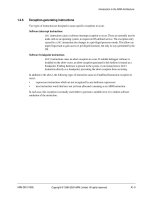
Enter name of top
level design entity
Entity name Specifies the name of the top level entity in the imported HDL files.
Import Quartus II
Project
On or Off When this option is on, you can specify the HDL to import using a Quartus II project file
(.qpf). The current HDL configuration is imported. To import a different revision, the
required revision should be specified in the Quartus II software. The source files used
by the Quartus II project must be in the same directory as your model file or be
explicitly referenced in the Quartus II settings file (.qsf). Error messages are issued for
any entities which cannot be found. Refer to the Quartus II documentation for
information about setting the current revision of a project and how to explicitly
reference the source files in your design.
1–6 Chapter 1: AltLab Library
HDL Import
DSP Builder Reference Manual © March 2009 Altera Corporation
Figure 1–2 shows an example of an imported HDL design implementing a simple
adder with four input ports (Input, Input1, Input2, sclrp), and two output ports
(Output, Output1).
The input and output interfaces to the imported VHDL must be defined using
std_logic_1164 types. If your design uses any other VHDL type definitions (such as
arithmetic or numeric types), you should write a wrapper which converts them to
std_logic or std_logic_vector.
HDL import only supports single clock designs. If a design with multiple clocks is
imported, one clock is used as the implicit clock and any others are shown as input
ports on the Simulink block.
1 HDL source files can be stored in any directory or hierarchy of directories.
Table 1–6 lists the supported megafunctions and LPM functions.
Table 1–7 on page 1–7 lists the megafunctions and LPM functions that are not
supported.
Browse .qpf file Click this button to browse for a Quartus II project file.
Sort top-level
ports by name
On or Off Turn on to sort the ports defined in the top-level HDL file alphabetically instead of using
the order specified in the HDL.
Compile — This button compiles a simulation model from the imported HDL and displays the ports
defined in the imported HDL on the block.
Table 1–5. HDL Import Block Parameters (Part 2 of 2)
Figure 1–2. Typical HDL Import Block
Table 1–6. Supported Megafunctions and LPM Functions
Megafunctions LPM Functions
a_graycounter
altaccumulate
altmult_add
altshift_taps
altsyncram
parallel_add
scfifo
lpm_abs
lpm_add_sub
lpm_compare
lpm_counter
lpm_mult (Note 1)
lpm_mux
lpm_ram_dp
Note to Table 1–6:
(1) The lpm_mult LPM function is not supported when configured to perform a squaring operation.
Chapter 1: AltLab Library 1–7
HDL Input
© March 2009 Altera Corporation DSP Builder Reference Manual
HDL Input
The HDL Input block should be connected directly to an input node in a subsystem.
It is intended for use with a HDL Entity block for black box simulation.
The type and bit width specified for the HDL Input block should match the type and
bit width on the corresponding input port in the HDL file referenced in the HDL
Entity block. This block is usually automatically generated by the Subsystem
Builder block.
You can optionally specify the external Simulink type. If set to Simulink Fixed
Point Type, the bit width is the same as the input. If set to Double, the width may
be truncated if the bit width is greater than 52.
Table 1–8 shows the HDL Input block parameters.
.
Table 1–9 on page 1–8 shows the HDL Input block I/O formats.
Table 1–7. Unsupported Megafunctions and LPM Functions
Megafunctions LPM Functions
alt3pram
altcam
altcdr
altclklock
altddio
altdpram
altera_mf_common
altfp_mult
altlvds
altmemmult
altmult_accum
altpll
altqpram
altsqrt
alt_exc_dpram
alt_exc_upcore
dcfifo
lpm_and
lpm_bustri
lpm_clshift
lpm_constant
lpm_decode
lpm_divide
lpm_ff
lpm_fifo
lpm_fifo_dc
lpm_inv
lpm_latch
lpm_or
lpm_pad
lpm_ram_dq
lpm_ram_io
lpm_rom
lpm_shiftreg
lpm_xor
Table 1–8. HDL Input Block Parameters
Name Value Description
Bus Type Signed Integer,
Signed Fractional,
Unsigned Integer,
Single Bit
Choose the number format of the bus.
[number of bits].[] >= 0
(Parameterizable)
Specify the number of bits to the left of the binary point, including the
sign bit. This parameter does not apply to single-bit buses.
[].[number of bits] >= 0
(Parameterizable)
Specify the number of bits to the right of the binary point. This parameter
applies only to signed fractional buses.
External Type Inferred,
Simulink Fixed Point Type,
Double
Specifies whether the external type is inferred from the Simulink block it
is connected to or explicitly set to either Simulink Fixed Point or Double
type. The default is Inferred.
1–8 Chapter 1: AltLab Library
HDL Output
DSP Builder Reference Manual © March 2009 Altera Corporation
HDL Output
The HDL Output block should be connected directly to an output node in a
subsystem. It is intended to be used with the HDL Entity block for black box
simulation.
The type and bit width specified for the HDL Output block should match the type
and bit width on the corresponding output port in the HDL file referenced in the HDL
Entity block. This block is usually automatically generated by the Subsystem
Builder block.
Table 1–10 shows the HDL Output block parameters.
Table 1–11 shows the HDL Output block I/O formats.
Table 1–9. HDL Input Block I/O Formats (Note 1)
I/O Simulink (2), (3) VHDL Type (4)
II1
[L1].[R1]
I1: out STD_LOGIC_VECTOR({L1 + R1 - 1} DOWNTO 0) Implicit - Optional
OO1
[LP].[RP]
O1: out STD_LOGIC_VECTOR({LP + RP - 1} DOWNTO 0) Explicit
Notes to Table 1–9:
(1) For signed integers and signed binary fractional numbers, the MSB is the sign bit.
(2) [L] is the number of bits on the left side of the binary point; [R] is the number of bits on the right side of the binary point. For signed or unsigned
integers R = 0, that is, [L].[0]. For single bits, R = 0, that is, [1] is a single bit.
(3) I1
[L].[R]
is an input port. O1
[L].[R]
is an output port.
(4) Explicit means that the port bit width information is a block parameter. Implicit means that the port bit width information is set by the data path
bit width propagation mechanism. To specify the bus format of an implicit input port, use a Bus Conversion block to set the width.
Table 1–10. HDL Output Block Parameters
Name Value Description
Bus Type Signed Integer,
Signed Fractional,
Unsigned Integer,
Single Bit
Choose the number format of the bus.
[number of bits].[] >= 0
(Parameterizable)
Specify the number of bits to the left of the binary point, including the sign bit.
This parameter does not apply to single-bit buses.
[].[number of bits] >= 0
(Parameterizable)
Specify the number of bits to the right of the binary point. This parameter applies
only to signed fractional buses.
Table 1–11. HDL Output Block I/O Formats (Note 1)
I/O Simulink (2), (3) VHDL Type (4)
II1
[L1].[R1]
I1: out STD_LOGIC_VECTOR({L1 + R1 - 1} DOWNTO 0) Implicit - Optional
OO1
[LP].[RP]
O1: out STD_LOGIC_VECTOR({LP + RP - 1} DOWNTO 0) Explicit
Notes to Table 1–11:
(1) For signed integers and signed binary fractional numbers, the MSB is the sign bit.
(2) [L] is the number of bits on the left side of the binary point; [R] is the number of bits on the right side of the binary point. For signed or unsigned
integers R = 0, that is, [L].[0]. For single bits, R = 0, that is, [1] is a single bit.
(3) I1
[L].[R]
is an input port. O1
[L].[R]
is an output port.
(4) Explicit means that the port bit width information is a block parameter. Implicit means that the port bit width information is set by the data path
bit width propagation mechanism. To specify the bus format of an implicit input port, use a Bus Conversion block to set the width.
Chapter 1: AltLab Library 1–9
HIL (Hardware in the Loop)
© March 2009 Altera Corporation DSP Builder Reference Manual
HIL (Hardware in the Loop)
The HIL (Hardware in the Loop) block allows you to use an FPGA as a simulation
device inside a Simulink design. This hardware accelerates the simulation time, and
also allows access to real hardware in a simulation.
To use an HIL block, you need an FPGA development board with a JTAG interface.
You can use any JTAG download cable, such as a ByteBlasterMV™, ByteBlaster™, or
USB-Blaster™ cable.
HIL supports advanced features, including:
■ Exported ports (allows the use of hardware components connected to the FPGA)
■ Burst and frame modes (improves HIL simulation speed)
1 This block supports only single clock designs with registered paths in a design. The
simulation results may be unreliable for combinational paths.
Table 1–12 shows the parameters specified in page 1 of the HIL dialog box.
Table 1–12. HIL Block Parameters, Page 1 (Part 1 of 2)
Name Value Description
Select the Quartus II
project
.qpf file Browse for a Quartus II project file which describes the hardware design used in the
HIL block.
Select the clock pin Port name Choose the clock pin name for the hardware design in the Quartus II software.
Select the reset pin Port name Choose the reset pin name for the hardware design in the Quartus II software.
Identify the signed
ports
Signed or
Unsigned
Set the number of bits and select the type (signed or unsigned) of each input and
output port in the hardware design.
Export On or Off When on, the selected port is exported on an FPGA pin (or on multiple pins for
buses). When off (the default), the port is exported to the Simulink model.
Select the reset level Active_High,
Active_Low
Choose the reset level that matches the setting in the original design. For designs
originated from the standard blockset, the reset level is specified in the Clock or
Clock_Derived block. (If no clock block is explicitly used in your design, a
default clock with reset level active high is used.) For designs originated from the
advanced blockset, the reset level is specified in the Signals block.
Burst Mode On or Off When on, allows sending data to the FPGA in bursts. This improves the simulation
speed, but delays the outputs by the burst length used. When Off, it defaults to
single-step mode.
Burst Length (Note 1) Specify the length of a burst ("1" would be equivalent to disabling burst mode). Use
higher values to produce faster simulations (although the extra gain becomes
negligible as bigger burst sizes are used).
Frame Mode On or Off Used in burst mode when data is sent or received in frames. When on, allows
synchronizing of the output data frames to the input data frames.
Input Sync Port name Choose the input port used as the synchronization signal in frame mode.
Output Sync Port name Choose the output port used as the synchronization signal in frame mode.
Sampling Period Integer Specify the sample time period in seconds. (A value of -1 means that the sampling
period is inherited from the block connected to the inputs.)
1–10 Chapter 1: AltLab Library
HIL (Hardware in the Loop)
DSP Builder Reference Manual © March 2009 Altera Corporation
1 The HIL block will need recompilation if the Quartus II project, clock pin, or any of
the exported ports are changed.
Table 1–13 shows the parameters specified in page 2 of the HIL dialog box.
Figure 1–3 shows an example using the HIL block.
1 Refer to the “Using Hardware in the Loop (HIL)” chapter in the DSP Builder User Guide
for more information.
Assert “Sclr” before
starting the simulation
On or Off When on, asserts the synchronous clear signal before the simulation starts.
Note to Table 1–12:
(1) The record size is 32×1024×1024 which is the product of (packet size) × (burst length) while the packet size is the larger of the total input data
width and the total output data width. For example, for a packet size of 1024 bits, the burst length can be set to 32×1024. However, due to the
limitations of the JTAG interface, the optimal record size is between 1 to 2 MBPS (depending on the host computer, USB driver and cables).
Hence, setting a bigger burst size might not give significant speed up.
Table 1–12. HIL Block Parameters, Page 1 (Part 2 of 2)
Name Value Description
Table 1–13. HIL Block Parameters, Page 2
Name Value Description
FPGA device device name Choose the FPGA device.
Compile with Quartus II — Click this button to compile the HIL block with the Quartus II software.
JTAG Cable cable name Choose the JTAG cable.
Device in chain device location Choose the required entry for the location of the device.
Scan JTAG — Click this button to scan the JTAG interface for all JTAG cables attached to the
system (including any remote computers) and the devices on each JTAG cable.
The available cable names and device names are loaded into the JTAG Cable
and Device in chain list boxes.
Configure FPGA — Click this button to configure the FPGA.
Transcript window — Displays the progress of the compilation.
Figure 1–3. Example Using the HIL Block
Chapter 1: AltLab Library 1–11
Quartus II Global Project Assignment
© March 2009 Altera Corporation DSP Builder Reference Manual
Quartus II Global Project Assignment
This block passes Quartus
®
II global project assignments to the Quartus II project .
Each block sets a single assignment. If you need to make multiple assignments, you
can use multiple blocks as shown in Figure 1–4. These assignments could set
Quartus II compilation directives such as target device or timing requirements.
1 You cannot assign the device, family, or f
MAX
requirement using this block. Use the
Signal Compiler block to make device and family settings, or the Clock and
Clock_Derived blocks to make explicit clock settings.
f For a full list of Quartus II global assignments and their syntax, refer to the Quartus II
Settings File Reference Manual or use the following Quartus II shell command:
quartus_sh tcl_eval get_all_assignment_names
Table 1–14 shows the Quartus II Global Project Assignment block
parameters.
Figure 1–4 shows an example defining multiple assignments using Quartus II
Global Project Assignment blocks.
Quartus II Pinout Assignments
The Quartus II Pinout Assignments block passes Quartus
®
II project pinout
assignments to the Quartus II project generated by the Signal Compiler block.
This block must be used only at the top level of your model. This block sets the pinout
location of the Input or Output blocks in your model which have the specified pin
names.
For buses, use a comma to separate the bit pin assignment location from LSB to MSB.
Table 1–14. Quartus II Global Project Assignment Block Parameters
Name Value Description
Assignment Name String Specify the assignment name.
Assignment Value String Specify the assignment value with any optional arguments. Note that any values or
arguments that contain spaces or other special characters must be enclosed in quotes.
Figure 1–4. Assignments Using Quartus II Global Project Assignment Blocks
1–12 Chapter 1: AltLab Library
Resource Usage
DSP Builder Reference Manual © March 2009 Altera Corporation
For example:
Pin Name: abc
Pin Location: Pin_AA, Pin_AB, Pin_AC
assigns abc[0] to Pin_AA, abc[1] to Pin_AB, and abc[2] to Pin_AC.
To set the pin assignment for a clock, use the name of the Clock block (for example,
the default is named clock) for the pin name. For example:
Pin Name: clock
Pin Location: Pin_AM17
To set the pin assignment for a reset, use the name of the reset signal specified in the
Clock block (for example the default global reset is named aclr) for the pin name.
For example:
Pin Name: aclr
Pin Location: Pin_B4
Table 1–15 shows the Quartus II Pinout Assignments block parameters.
Figure 1–5 shows an example using the Quartus II Pinout Assignments block.
Resource Usage
You can use the Resource Usage block to check the hardware used, display timing
information and highlight the critical paths in your design.
1 Your model file must be saved and Signal Compiler must have been run before
you can use the Resource Usage block.
The Resource Usage block displays an estimate of the logic, block RAM and DSP
blocks resources required by your design.
Table 1–15. Quartus II Pinout Assignments Block Parameters
Name Value Description
Pin Name String The pin name must be the exact instance name of the Input or Output block from
the IO & Bus DSP Builder Simulink library folder.
Pin Location String Pin location value of the FPGA IO. Refer to the Quartus II Help for the pinout values of a
given device.
Figure 1–5. Assignments Using Quartus II Pinout Assignments Blocks
Chapter 1: AltLab Library 1–13
Signal Compiler
© March 2009 Altera Corporation DSP Builder Reference Manual
You can double-click on the Resource Usage block to display more detailed
information about the blocks in your design that generate hardware.
f The information displayed depends on the selected device family. Refer to the device
documentation for more information.
You can also choose the Timing tab and click Highlight path to highlight the critical
paths on your design.
1 When the source and destination shown in the dialog box are the same and a single
block is highlighted, the critical path is due to the internal function or a feedback loop.
Signal Compiler
You can use the Signal Compiler block to create and compile a Quartus II project
for your DSP Builder design, and to program your design onto an Altera
®
FPGA.
1 Your model file must be saved before you can use the Signal Compiler block.
Table 1–16 shows the controls and parameters for the Signal Compiler block.
Table 1–16. Signal Compiler Block Parameters Settings Page (Part 1 of 2)
Name Value Description
Family Stratix
®
, Stratix GX,
Stratix II, Stratix II GX,
Stratix III, Stratix IV,
Arria
®
GX, Arria II GX,
Cyclone
®
, Cyclone II,
Cyclone III
Choose which Altera device family you want to target.
If you are using the automated design flow, the Quartus II software
automatically chooses the smallest device in which your design fits.
Use Board Block
to Specify Device
On or Off Turn on to get the device information from the development board block.
Compile — Click this button to compile your design.
Scan JTAG
List of ports connected to
the JTAG cable.
Choose the required JTAG cable port.
Program — Click this button to download your design to the connected development
board.
Analyze — Click this button to analyze the DSP Builder system.
Synthesis — Click this button to run Quartus II synthesis.
Fitter — Click this button to run the Quartus II Fitter tool.
Enable SignalTap II On or Off Turn on to enable use of a SignalTap II Logic Analyzer block
in your design. Turning on this setting will add extra logic and memory to
capture signals in hardware in real time.
SignalTap II depth 2, 4, 8, 16, 32, 64, 128,
256, 512, 1k, 2K, 4K, 8K
Choose the required depth for the SignalTap II Logic Analyzer.
SignalTap II clock User defined Specifies the clock to use for capturing data using the SignalTap II feature.
Choose from a list of available signals.
1–14 Chapter 1: AltLab Library
SignalTap II Logic Analyzer
DSP Builder Reference Manual © March 2009 Altera Corporation
1 The clock and reset signals can be specified using a Clock or Clock_Derived block.
SignalTap II Logic Analyzer
As programmable logic design complexity increases, system verification in software
becomes time consuming and replicating real-world stimulus is increasingly difficult.
To alleviate these problems, you can supplement traditional system verification with
efficient board-level verification.
DSP Builder supports the SignalTap
®
II embedded logic analyzer, which lets you
capture signal activity from internal Altera device nodes while the system under test
runs at speed. You can use the SignalTap II Logic Analyzer block to set up
event triggers, configure memory, and display captured waveforms.
You use the SignalTap II Node block to select signals to monitor. Samples are
saved to internal embedded system blocks (ESBs) when the logic analyzer is
triggered, and are subsequently streamed off chip via the JTAG port using an Altera
download cable. The captured data is then stored in a text file, displayed as a
waveform in a MATLAB plot, and transferred to the MATLAB workspace as a global
variable.
Table 1–17 shows the SignalTap II Logic Analyzer block parameters.
f For detailed instructions on using the SignalTap II Logic Analyzer and
SignalTap II Node blocks, refer to the “Performing SignalTap II Logic Analysis”
chapter in the DSP Builder User Guide.
Use Base Clock On or Off Turn on if you want to use the base clock for the SignalTap II Logic
Analyzer.
Export — Exports synthesizable HDL to a user-specified directory.
Table 1–16. Signal Compiler Block Parameters Settings Page (Part 2 of 2)
Name Value Description
Table 1–17. SignalTap II Logic Analyzer Block Parameters Page
Name Value Description
Scan JTAG
List of ports connected
to the JTAG cable.
Choose the required JTAG cable port.
Acquire — Click this button to acquire data from the development board.
SignalTap Nodes List of SignalTap II node
blocks.
Click to select a node and use the Change button to set a trigger condition.
Change Don’t Care, High, Low,
Rising Edge, Falling
Edge, Either Edge
Click the Change button to set the specified logic condition as the trigger
condition for the selected node.
Chapter 1: AltLab Library 1–15
SignalTap II Node
© March 2009 Altera Corporation DSP Builder Reference Manual
Figure 1–6 shows an example using the SignalTap II Node block and the
SignalTap II Logic Analyzer block.
SignalTap II Node
You can use the SignalTap II Node block with the SignalTap II Logic
Analyzer block to capture signal activity from internal Altera
device nodes while the
system under test runs at speed. The SignalTap II Node block indicates the signals
(also called nodes) for which you want to capture activity.
The SignalTap II Node block has no parameters.
For an example of a design using the SignalTap II Logic Node block, refer to
the description of the SignalTap II Logic Analyzer block.
f Refer to the “Performing SignalTap II Logic Analysis” chapter in the DSP Builder User
Guide for more information.
Simulation Accelerator
The Simulation Accelerator block is no longer supported. An error message is
issued if you attempt to enable bit-accurate simulation.
The Simulation Accelerator block has no parameters.
1 This block is available for backwards compatibility only. All designs should be
simulated in cycle-accurate mode.
Figure 1–6. Example SignalTap II Analysis Model
1–16 Chapter 1: AltLab Library
Subsystem Builder
DSP Builder Reference Manual © March 2009 Altera Corporation
Subsystem Builder
The Subsystem Builder block allows you to build black box subsystems that
synthesize using user-supplied VHDL and simulate using non-DSP Builder Simulink
blocks. This is an alternative to using HDL Import and can give better simulation
speed. You can also use this block if HDL Import cannot be used due to unsupported
megafunctions or LPMs.
The subsystem connects the inputs and outputs in the specified VHDL to HDL Input
and HDL Output blocks and creates an HDL Entity block which you can modify if
the clock and reset signals are not correctly identified.
The Subsystem Builder block automatically maps any input ports named
simulink_clock in the VHDL entity section to the global VHDL clock signal, and
maps any input ports named simulink_sclr in the VHDL entity section to the
global VHDL synchronous clear signal.
The VHDL entity should be formatted according to the following guidelines:
■ The VHDL file should contain a single entity
■ Port direction: in or out
■ Port type: STD_LOGIC or STD_LOGIC_VECTOR
■ Bus size:
■ a(7 DOWNTO 0) is supported (0 is the LSB, and must be 0)
■ a(8 DOWNTO 1) is not supported
■ a(0 TO 7) is not supported
■ Single port declaration per line:
■ a:STD_LOGIC; is supported
■ a,b,c:STD_LOGIC; is not supported
The Verilog HDL module should be formatted according to the following guidelines:
■ The Verilog HDL file should contain a single module
■ Port direction: input or output
■ Bus size:
■ input [7:0] a; is correct (0 is the LSB, and must be 0)
■ input [8:1] a; is not supported
■ input [0:7] a; is not supported
■ Single port declaration per line:
■ input [7:0] a; is correct
■ input [7:0] a,b,c; is not supported
To use the Subsystem Builder block, drag and drop it into your model, click
Select HDL File, specify the file to import, and click Build.
Chapter 1: AltLab Library 1–17
TestBench
© March 2009 Altera Corporation DSP Builder Reference Manual
Table 1–18 shows the Subsystem Builder block parameters.
Figure 1–7 shows an example using the Subsystem Builder block.
TestBench
The TestBench block controls the generation of a testbench. You can also use the
TestBench block to run ModelSim and compare Simulink results with the ModelSim
simulation. Input and output vectors are generated when you use the Compare
against HDL option in the Simple tab or Run Simulink in the Advanced tab.
1 Enabling testbench generation may slow simulation as all input and output values are
stored to a file.
Table 1–19 shows the TestBench block parameters.
Table 1–18. Subsystem Builder Block Parameters
Name Value Description
Select HDL File User defined Browse for the VHDL or Verilog HDL file to import.
Build SubSystem — Click this button to build a subsystem for the selected HDL file.
Figure 1–7. Example Using the Subsystem Builder Block
Table 1–19. TestBench Block Parameters
Name Value Description
Enable Testbench generation On or Off Turn on to enable automatic testbench generation.
Compare against HDL — Click this button to generate HDL, run Simulink and compare the Simulink
simulation results with ModelSim.
Generate HDL — Click this button to generate a VHDL testbench from the Simulink model.
Run Simulink — Re-run the Simulink simulation.
Run ModelSim — Load the testbench into the ModelSim simulator.
Launch GUI On or Off Turn on to launch the ModelSim graphical user interface.
Compare Results — Compare the Simulink and ModelSim results.
Mark ModelSim Unknowns
(X’s) as
Error,
Warning,
Info
Choose whether ModelSim unknown values are displayed as error, warning
or info messages. Errors are displayed in red, warnings in blue and info in
green.
Maximum number of
mismatches to display
>=0
Default = 10
Specify the maximum number of mismatches to display.
1–18 Chapter 1: AltLab Library
VCD Sink
DSP Builder Reference Manual © March 2009 Altera Corporation
VCD Sink
The VCD Sink block is used to export Simulink signals to a third-party waveform
viewer. When you run the simulation of your model, the VCD Sink block generates a
value change dump (.vcd) file named <VCD Sink block name>.vcd which can be read
by a third-party waveform viewer.
To use the VCD Sink block in your Simulink model, perform the following steps:
1. Add a VCD Sink block to your Simulink model.
2. Connect the simulink signals you want to display in a third-party waveform
viewer to the VCD Sink block.
3. Run the Simulink simulation.
4. Read the VCD file in the third-party waveform viewer.
If you are using the ModelSim software to view waveforms, run the script
<VCD Sink block path>_vcd.tcl where the path is the hierarchical path of the block in
the Simulink model. That is: <model name>_<subsystem names>_<block name> each
separated by underscore character.
This Tcl script converts VCD files to ModelSim waveform format (.wlf), starts the
waveform viewer, and displays the signals. If you are using any other third-party
viewer, load the VCD file directly into the viewer.
The VCD Sink block does not have any hardware representation and therefore does
not appear in the VHDL RTL representation created by the Signal Compiler block.
Table 1–20 shows the parameters for the VCD Sink block.
Figure 1–8 shows an example of the VCD Sink block
Table 1–20. VCD Sink Block Parameters
Name Value Description
Number of Inputs An integer greater than 0 Specify the number of input ports on the VCD Sink block.
Figure 1–8. Simulink Model Using the VCD Sink Block
© March 2009 Altera Corporation DSP Builder Reference Manual
2. Arithmetic Library
The Arithmetic library contains two’s complement signed arithmetic blocks such as
multipliers and adders. Some blocks have a Use Dedicated Circuitry option, which
implements functionality into dedicated hardware in the Altera FPGA devices (that is,
in the dedicated DSP blocks of these devices).
f For more information on these device families, refer to the device documentation on
the Altera literature website.
The Arithmetic library contains the following blocks:
■ Barrel Shifter
■ Bit Level Sum of Products
■ Comparator
■ Counter
■ Differentiator
■ Divider
■ DSP
■ Gain
■ Increment Decrement
■ Integrator
■ Magnitude
■ Multiplier
■ Multiply Accumulate
■ Multiply Add
■ Parallel Adder Subtractor
■ Pipelined Adder
■ Product
■ SOP Tap
■ Square Root
■ Sum of Products