Tài liệu Industrial Power Engineering and Applications Handbook P2 docx
Bạn đang xem bản rút gọn của tài liệu. Xem và tải ngay bản đầy đủ của tài liệu tại đây (492.33 KB, 10 trang )
1/22 Industrial Power Engineering and Applications Handbook
Figure 1.18(a)
Screen protected drip proof (SPDP) squirrel
cage motor (Cooling system ICOAI)
Figure
1.18(b) Screen protected drip proof slip ring motor
(Cooling system
ICOAI)
Figure
1.18(c) Large
SPDP
squirrel cage motor (enclosure IP 12) (Cooling system ICOAI)
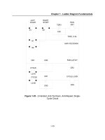
1 Access for checking air gap
2 Air-deflecting baffle
3 Coil bracing ring
4
Fan
5 Rotor end ring
6
Rotor bars
7 Stator core
8 Fully-formed coils of the two
layer stator winding
10 Core duct separator
11
Preformed coil in section
12 End winding connections
13 Bearing endshield
14 Terminal
box
with bolted on
cable sealing end
15 Shaft
16 Grease ejector handle
17 Grease collector
18
Anti-friction bearing with
grease regulator
19 Grease impeller
19
18
17
16 15 14
Figure
1.18(d) Cross-sectional view of a large screen protected motor showing the cooling circuit (Cooling system ICOAI)
(Courtesy: NGEF
Ltd)
Theory, performance and constructional features
of
induction motors 1/23
Squirrel cage rotor
1.1
5
Degree
of
protection
The nomenclatures used above to define an enclosure
were earlier interpreted in different ways by different
manufacturers. To achieve harmonization,
IEC
60034-
1
has eliminated the use of these codes. Instead, designation
IP,
followed by two characteristic numerals according to
IEC
60034-5,
is now introduced to define an enclosure.
The first characteristic numeral defines the protection of
personnel from contact with live or moving parts inside
the enclosure and of machines against the ingress of
solid foreign bodies. The second numeral defines the
type of protection against ingress of water. Tables
1.10
and
1.11
show these requirements.
Table 1.10 Types
of
protection against contact with live or
moving parts
First Type
of
protection
characteristic
number
as
in
IEC
60034-5
Figure 1.19(a) TEFC squirrel cage motor (Cooling system ICOAI)
(Courtesy:
NGEF
Ltd)
Slip ring rotor
Figure 1.19(b) TEFC slip ring motor (Cooling system KOA1
(Courtesy:
NGEF
Ltd)
No
special protection of persons against accidental
or
inadvertent contact with live
or
moving parts
inside the enclosure.
No
protection of equipment against ingress of
solid foreign bodies.
Protection against accidental or inadvertent
contact with live and moving parts inside the
enclosure by a larger surface
of
the human body,
for example a hand, but not against deliberate
access to such parts.
Protection against ingress of large solid foreign
bodies (diameter greater than
50
mm).
Protection against contact with live
or
moving
parts inside the enclosure by fingers.
Protection against ingress of small solid foreign
bodies (diameter greater than
12
mm).
Protection against contact with live or moving
parts inside the enclosure by tools, wires
or
objects
having a thickness greater than
2.5
mm.
Protection against ingress of small solid foreign
bodies (diameter greater than
2.5
mm).
Protection against contact with live
or
moving
parts inside the enclosure by tools, wires,
or
such
objects of thicknesses greater than
1
mm.
Protection against ingress of small solid foreign
bodies (diameter greater than
1
mm) excluding
the ventilation openings (intake and discharge)
and the drain hole of the enclosed machine which
may have degree
2
protection.
Complete protection against contact with live
or
moving parts inside the enclosure.
Protection against harmful deposit of dust.
The
ingress of duct is not totally prevented, but dust
will not be able to enter in an amount sufficient
to harm the machine.
Totally dust-tight.
No
ingress of dust.
1/24
Industrial Power Engineering and Applications Handbook
Table
1.11
Types
of
Protection against
ingress
of
water
Second
Type
of
protection
characteristic
number
No
special protection
Dripping water (vertically falling droplets) will
have
no
harmful
effect.
Droplets
of
water falling at any angle up
to
15"
from
the
vertical will have no harmful effect.
Water falling
as
a spray at
an
angle equal
to
or
smaller than
60"
from
the
vertical will have
no
harmful effect.
Water splashed under stated conditions against
the machine from any direction will have no
harmful effect.
Water injected under stated conditions through a
nozzle against the machine from any direction
will have
no
harmful effect.
Water from heavy seas will not enter the machine
in a
harmful
quantity.
Ingress
of
water in the machine immersed in
water under stated conditions of pressure and
time will not
be
possible in a harmful quantity.
Ingress of water into the machine immersed in
water under specified pressure and for an
indefinite
time
will not
be
possible in a harmful
quantity.
1.16
Cooling
systems
in
large
motors
The cooling system in large motors becomes vital, as
one fan cannot cover the entire length of the motor body
or cool the inside bulk of the motor windings. Now a
more judicious design
is
required for adequate cooling
to eliminate any hot spots in the rotor, stator
or
the
overhangs of the stator windings and bearings etc. There
are many cooling systems adopted by various rnanu-
facturers, depending upon the size of the machine and
the heat generated in various parts during full-load
continuous running. The cooling system may be self-
ventilated, closed circuit, not requiring any external source
to augment the cooling system, or a forced cooling system,
employing an external source, to basically work as heat
exchangers to dissipate the heat.
Thus,
there may be a
variety of cooling systems to cool a large machine.
IEC
60034-6
has specified a number of probable cooling
systems, as adopted by various manufacturers. The more
commonly used practices are shown in Table 1.12.
According to this specification any cooling system may
be expressed by the letters IC (international cooling)
followed by
1 A number to indicate the arrangement of the cooling
circuit as in column 1 of Table 1.12.
2
Each cooling circuit is then identified
for
the primary
cooling medium by a letter
A,
H
or
W etc. which
specifies the coolant
as
noted below:
3
4
For gases Air
-
A
Freon
-
F
Hydrogen
-
H
Nitrogen
-
N
Carbon
dioxide
-
C
Oil
-
U
For liquids Water
-
W
The letter
is
then followed by a number, describing
the method to circulate the coolant as in column
3
of
Table
1.12.
Another letter and a number
are
added after the above
to describe the secondary cooling system.
Example
IC3AlW6
Coding arrangement
as
in
column
1,
Table
1.12
Primary cooling
system
Method
of
circulating
the
coolant
as
in column
3
of
Table
1.12
Secondary cooling system
1
J
I
Depending upon its size, a machine may adopt more
than one cooling system, with separate systems for the
stator and the rotor and sometimes even for bearings.
To
define the cooling system of such a machine, each system
must be separately described. For more details refer
to
The following are some
of
the more prevalent systems
Tube Ventilated Self Cooled (TV)
Closed Air Circuit Water Cooled (CACW)
Closed Air Circuit Air Cooled (CACA)
The above cooling systems will generally comprise
the following:
1
Tube ventilation
In this system cooling tubes which
work as heat exchangers are welded between the core
packet
and
the outer frame and are open only
to
the
atmosphere. See to Figures 1.20 (a)-(c). One fan inside
the stator, mounted on the rotor shaft, transfers the
internal hot air through the tube walls which form the
internal closed cooling circuit. A second fan mounted
outside at the
NDE
blows out the internal hot air of
the tubes to the atmosphere and replaces it with fresh
cool air from the other side. This forms a separate
external cooling circuit.
2
ClosedAir Circuit Water Cooled (CACW)
The motor's
interior hot air forms one part of the closed air circuit
that is circulated by the motor's internal fans. A separate
heat exchanger
is
mounted on top
of
the motor
as
the
cooling water circuit. This forms the second cooling
circuit.
IEC
60034-6.
for totally enclosed large machines:
Theory, performance and constructional features
of
induction motors
1/25
Table
1.12
Normal
systems
of
cooling
for
totally
enclosed large machines
~~ ~
First characteristic Description
number to indicate
the cooling system
1
2
0
I
J
5
6
Free circulation
of
the coolant from the
machine to the surrounding medium
Inlet pipe-circulation:
The coolant flows to
the machine through inlet pipes from
a
source
other than the surrounding medium and then
freely discharges to the surrounding medium
(as
in
the use
of
separately driven blowers)
Outlet pipe circulation:
The coolant is drawn
from the surrounding medium but is discharged
remotely through the pipes
Inlet and outlet pipe circulation:
The coolant
flows from a source other than the surrounding
medium through the inlet pipes and is
discharged remotely through the outlet pipes
Frame surface cooled
(using the surrounding
medium): The primary coolant is circulated
in
a
closed circuit and dissipates heat to the
secondary coolant, which is the surrounding
medium
in
contact with the outside surface
of
the machine. The surface may be smooth or
ribbed, to improve on heat transfer efficiency
(as,
in a TEFC
or
tube ventilated motor (Figures
1.19
and 1.20)
Integral heat exchanger
(using surrounding
medium):
As
at
No.
4
above, except that the
medium surrounding the machine is
a
heat
exchanger, which is built-in
as
an
integral part
of
the machine like
a
totally enclosed. tube-
ventilated motor (Figure 1.20)
Machine-mounted heat exchanger
(using the
surrounding medium):
As
at
No.
5
above,
except that the heat exchanger
is
neither
externally mounted nor forms an integral part
of the machine. Rather
it
is mounted
as
an
independent unit, directly
on
the machine
(Figures
1.21
and
1.22)
Integral heat exchanger
(not using the
surrounding medium):
As
at
No.
5
above,
except that the cooling medium is different
from the surrounding medium. It
can
be liquid
or gas
Machine-mounted heat exchanger
(not using
the surrounding medium):
As at
No.
‘6’ above
except that the cooling medium is different
from the surrounding medium. It can be liquid
or gas (Figures 1.21 and 1.22)
Separately mounted heat exchanger:
The
primary coolant is circulated in a closed circuit
and dissipates heat to the secondary coolant.
It can be
a
heat exchanger
as
an independent
unit
separately mounted
Second characteristic Description
number
for
means
of
supplying power to
circulate the coolant
3
4
0
1
2
3
4
5
6
7
8
9
Free
convection:
No
external power source
is essential. Heat dissipation
is
achieved
through natural convection like
a
surface
cooled motor
Self-circulation:
Movement of the coolant
is normally through a fan mounted
on
the
rotor shaft, like a normal fan cooled
motor
(Figures l.lS(a)-(d) and
1.19(a)
and (b)
Circulation by integral independent
component:
Like
a
fan, driven by an
electric motor, and the power is drawn from
a separate source. rather than the main
machine itself
Circulation by independent component
mounted on the machine:
As
at
No.
5
above, but the movement
of
the coolant ia
through an intermediate component and
mounted
on
the
machine and not an integral
part of the machine
Circulation by an entirely separate
system:
As
at
No.
6
above, but the
circulation of the coolant is by
an
entirely
independent system, not forming
a
part of
the main machine in any way and mounted
separately like
a
water-distribution system
or
a
gas-circulation system
Circulation by relative displacement:
As
at
No.
0
above, except that instead of
surface cooling the cooling is achieved
through the relative movement of the
coolant over the machine
This numeral is used for circulation
by
any means other than stated above
1/26
Industrial Power Engineering and Applications Handbook
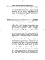
Figure
1.20(a)
Totally enclosed tube ventilated (TETV) squirrel cage motor (Cooling system IC5A111) (Courtesy: BHEL)
Figure
1.20(b)
A typical cooling circuit type IC5AIAI
1
Lifting lug
12
Handle for emptying
1
2345678
9
8
9
10
11
Air baffle
Coil bracing ring
Cooling tubes
Short-circuiting ring
Stator core packet
Two-layer fully formed
coils of stator winding
Air guide shell
Bearing endshield
Fan for outer air
circuit
Fan hood with
protective grid for
cooling air intake
13
14
15
16
17
18
19
20
21
grease collecting box
Welded frame
Terminal box with
cable sealing box
Rotor core packet
Section bars of the
squirrel cage
Rotor end plate
Grease collecting box
Grease thrower of
labyrinth seal
Opening for checking
air gap
Fan for inner air
circuit
1
10
11
12
13
12
17
16 15 14
Figure
1.20(c)
Cross-sectional view of a large tube-ventilated squirrel cage motor showing the cooling circuit (Cooling system
IC5AIA1) (Courtesy:
NGEF
Ltd)
Theory, performance and constructional features
of
induction motors
1/27
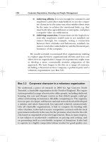
The heat exchanger consists of a large number of
cooling tubes connected to the stator through headers/
ducts. The tubes may have coils of copper wire wound
around them to enhance their cooling capacity. Filtered
water (soft water), to avoid scaling of tubes, is circulated
through these tubes. The hot air circulating through
the motor stator and rotor ducts passes through these
heat exchangers and becomes cooled. See Figure 1.21.
3
Closed Air Circuit Air Cooled (CACA)
This cooling
system is the same as for CACW except that, instead
of water, air flows through the top-mounted heat
exchangers. See Figures 1.21 and 1.22.
1
.I7
Single-phase motors
Application
-
Domestic appliances
-
Small machine tools
-
Industrial and domestic fans, pumps,
polishers, grinders, compressors and
blowers etc.
1
.I
8
Theory
of
operation
A single-phase winding cannot develop a rotating field,
unlike a multiphase winding. But once it is rotated, it
will continue rotating even when the rotating force is
removed
so
long as the winding is connected to a supply
source. To provide a rotating magnetic field, an auxiliary
winding or start winding is therefore necessary across
the main winding. It is placed at
90"
from the main
winding and connected in parallel to it, as shown
in
Figures 1.23 and 1.24. The impedances of the two
windings are kept
so
that they are able to provide a phase
shift between their own magnetic fields. This phase shift
provides a rotating magnetic field as already discussed.
The auxiliary windings may be one of the following types:
I
Split phase winding
When another inductive winding is placed across the
main winding (Figure 1.23(a) and (b))
so
that
RIX,,
of the auxiliary winding is high, a phase shift will
occur between the two windings. This shift will be
low and much less than
90°,
as explained in the phasor
diagram (Figure 1.23(c)). But it can be made adequate
by increasing the
R,
so
that a rotating field may develop
sufficiently to rotate the rotor. The higher the ratio
RIX,,,
the higher will be the starting torque, as
RIX,,
will move closer to the applied voltage
V,
and help to
increase the phase shift. In such motors the starting
torque,
T,,,
is low and running speed-torque
characteristics poor as illustrated in Figure 1.23(d).
Figure 1.23(e) shows a general view.
2
Capacitor start winding
If the inductive auxiliary winding is replaced by a
capacitive winding by introducing a capacitor unit
in
series with it (Figure 1.24(a) and (b)) the phase shift
will approach
90"
(Figure 1.24(c)) and develop a high
starting torque. When this capacitor is removed on a
run, the running torque characteristics become the
same as for a split-phase motor. Figure 1.24(d)
illustrates a rough speed-torque characteristics of such
a motor.
In both the above methods a speed-operated
centrifugal switch is provided with auxiliary winding
to disconnect the winding when the motor has reached
about
75-85%
of its rated speed. Figure 1.24(e) shows
a general view.
3
Capacitor start and capacitor run windings
When the running torque requirement is high but
the starting torque requirement not as high then a
Figure
1.21
(Courtesy:
BHEL)
Closed
air circuit, air cooled
(CACA)
squirrel cage motors (likely cooling systems
IC6AlA1
or
IC6AlA6)
1/28
Industrial Power Engineering and Applications Handbook
frame
Figure
1.22
Cooling cycle for a CACA (IC6AlA6)
or
CACW(IC9A6W7) motor
capacitor
of
a
low value,
so
that the capacitor current
may remain less than the magnetizing components
of
the two windings, may be provided and the
disconnecting switch removed. Figures
1.25(Ul)
and (b,j are drawn with the switch removed. The
starting torque in this case may not be very high
but the running torque would be higher as required.
The value
of
capacitor
C1
would depend upon the
value
of
L1
and the running torque requirement.
We can improve the starting performance
of
the
above method by providing
C
in two parts, one for
start
Cz,
of
a
much higher value, depending upon
the requirement
of
TFt,
through
a
disconnect switch
(Figures
1
.25(u2)
and
(b2)),
and the other
C,,
for
a
run of a much lower value
(so
that
IC,
<
Zmj.
Notes
1
The size of capacitors
C,
C,
or
C2
will depend upon the
horsepower
of
the motor and the torque requirement of the
load.
For
starting duty capacitors generally in the range of
30-
100
pF
and
for
a
run
of 2-20
pF
will
be
adequate.
Whenever frequent switchings are
likely,
high transient voltages
may
develop and harm the motor windings and the capacitors.
Fast
discharge facilities must
be
provided across the capacitor
terminals to damp such transients quickly. See Section
25.7,
for
more
details
on
discharge devices.
2
4
Shaded
pole
motors
Applications requiring extremely small motors, in both
size and horsepower, may be designed for shaded
pole construction. Electronic drives, cassette players,
recorders and similar applications need an extremely
small size of motor,
as
small as
1
W
(1/746
h.p.j. Such
motors can he designed in shaded pole.
The stator is
of
a salient pole type that protrudes
outwards within the stator housing similar to a d.c.
machine but
is
made
of
steel laminations.
A
small
side end portion
of
each pole
is
split and fitted with a
heavy copper ring as shown in Figure 1.26(a). This
ring is called
a
shading coil,
as
it shades the normal
flux distribution through that portion of the pole and
substitutes for
a
split phase and provides
the
required
second winding. The stator poles are wound
as
usual
and the end terminals are brought out to receive the
a.c. supply. Figure 1.26(b) illustrates a simple two-
pole machine. When the voltage is applied across the
stator windings,
a
magnetic flux is developed in the
entire pole, which cuts the copper ring arranged at
the tip
of
the pole. The main flux, thus cutting the
copper coil (ring), induces a current in the ring.
The current in the copper ring opposes the main
flux in that area of the pole and behaves like an artificial
second winding, and develops
a
rotating field. Although
the torque
so
developed is extremely low, it is enough
to rotate such small drives, requiring an extremely
low starting torque, of the order of
40-50%
of
the
full load torque.
Theory, performance and constructional features
of
induction motors
1/29
0-
Vr(1-4)
-0
Main
Im
winding
Disconnect
switch
Start hnding
XL
>
XL,
R
Note
Phase shift is obtained by increasing
-
XL1
(a) Schematic diagram
1
;
"1
I,",.
StartYwinding
(b) General arrangement
shift
b
lr
(c) Phasor diagram
Low starting and running torques
Figure
1.23
Since there is only one winding and the poles are
already shaded at one particular end, the direction of
the rotating flux is fixed and
so
is the direction
of
rotation of the rotor. The direction of rotation cannot
be altered as in the earlier cases. Since there is only
one winding and no need of a speed-operated
centrifugal switch, these motors require almost no
operational maintenance.
5
Universal
motors
These are series motors and are relatively compact
and lightweight compared to an a.c. motor. The use
of such motors is therefore common for hand tools
and home appliances and also for such applications
that require a high speed (above
3200
r.p.m) which is
not possible in an a.c. machine. Likely applications
are polishers, grinders and mixers. This motor runs
equally well on both a.c. and d.c. sources of supply.
t
3
P
COT,
Tsi
I
Centrifugal switch
opens here
Speed Nr
+
7585% N,
(d) Speed-torque characteristics of a split phase motor
(e) Split phase
1-4
motor [Courtesy:
AUE
(GE
Motors)]
Split-phase winding
The motor is designed conventionally, with a
laminated stator, a static magnetic field and a rotating
armature, as shown in Figure 1.27(a) and (b). The
armature and the field windings are connected in series
through two brushes, fitted on the armature extended
commutator assembly, to obtain the same direction of
field and armature currents. Thus, when the direction
of the line current reverses, the field and armature
currents also reverse. When operated on a.c., the torque
produced is in pulses, one pulse in each half cycle as
illustrated in Figure 1.27(c). The normal characteristics
for such motors are also illustrated in Figure 1.27(d).
The no-load speed may be designed very high, to the
order of
2000-20
000
r.p.m. but the speed on load
may be around
50-80%
of the no-load speed due to
windage and friction losses, which constitute a higher
percentage for such small to very small motors
(l/lo
to
1
h.p.). The required output speed for the type
of
application can be obtained through the use of gears.
Main
I,
Im
winding
-
-
-
Start hinding
(a) Schematic diagram
Disconnect
switch
ImiL
!
I,
-
r
-
Y
Start winding
(b) General arrangement
(c) Phasor diagram
High start but low running torques
Centrifugal switch
e
ET-
1
0
Nr
Centrifugal switch
e
ET-
1
0
Nr
@
Capacitor start and run windings
@
Run winding
@
Capacitor start and capacitor run windings
(d)
Speed-torque characteristics
of
capacitor start and
capacitor run motors
(e) Capacitor start or capacitor start-capacitor run
1-0
motor
Figure
1.24
Capacitor start winding
Theory, performance and constructional features of induction motors
1/31
r-
VW-S)
-7
y-
Vr(1-d
-7
-
-
L
L1
C
II
-
w
(ai) Schematic diagram
Main
Start winding
Cz
=
5
to
6
times
Cl
(a2) Schematic diagram
vr(l-$)
winding
Start winding
-
Start winding
General arrangement
(bl)
Low start
but
high running torques
Cl
=
Run capacitor
C,
=
Start capacitor
General arrangement
(b2)
High start and high running torques
Figure
1.25
Capacitor start and capacitor run windings
Shading coil (copper ring)
Laminated stator core
Squirrel cage rotor
7
Shading coil (copper ring)
Figure
1.26(a)
General arrangement
of
a shaded pole motor
Figure
1.26(b)
Shaded pole
1-g
motor [(Courtesy: AUE (GE Motors)]