Tài liệu Industrial Power Engineering and Applications Handbook P1 docx
Bạn đang xem bản rút gọn của tài liệu. Xem và tải ngay bản đầy đủ của tài liệu tại đây (1.23 MB, 40 trang )
Inaustrial Power
Engineering
and
Applications
Handbook
I
K.C.
Agra
Wal
QiB
Newnes NEWNES POWER ENGINEERING SERIES
Industrial Power
Engineering and
Applications Handbook
NEWNES POWER ENGINEERING SERIES
Series editors
Professor TJE Miller, University
of
Glasgow,
UK
Associate Professor Duane Hanselman, University
of
Maine, USA
Professor Thomas M Jahns, University of Wisconsin-Madison, USA
Professor Jim McDonald, University
of
Strathclyde, UK
Newnes Power Engineering Series
is a new series of advanced reference texts covering the core areas of
modern electrical power engineering, encompassing transmission and distribution, machines and drives, power
electronics, and related areas of electricity generation, distribution and utilization. The series
is
designed
for
a
wide audience of enginccrs, academics, and postgraduate students, and its focus is international, which is
reflected in the editorial team. The titles in the series offer concise but rigorous coverage of essential topics
within power engineering, with a special focus on areas undergoing rapid development.
The series complements the long-established range of Newnes titles in power engineering, which includes the
Electrical Engineer’s Reference
Book,
first published by Newnes in
1945,
and the classic
J&P
Transformer
Book,
as
well as a wide selection
of
recent titles for professionals, students and engineers at
all
levels.
Further information on the
Newnes Power Engineering Series
in available from and
www.newnespress.com
Please send book proposals
to
Matthew Deans, Newnes Publisher
matthew.deans @repp.co.uk
Other titles in the Newnes Power Engineering Series
Acha, Agelidis, Anaya
&
Miller Electronic Control in Electrical System
0
7506
5
126
1
Miller (ed.) Electronic Control of Switched Relunctance Machines
0
7506 5073 7
NEWNES POWER ENGINEERING SERIES
Industrial Power
Engineering and
Applications Handbook
K.C.
Agrawal
Newnes
BOSTON
OXFORD
AUCKLAND JOHANNESBURG MELBOURNE NEW
DELHI
I
TO
my
parents
1
Copyright
0
200 1 by Butterworth-Heinemann
member
of the Reed Elsevier
All rights reserved.
No
part of this publication may be reproduced, stored in a retrieval system,
or
transmitted in
any form
or
by any means, electronic, mechanical, photocopying, recording, or otherwise,
without the prior written permission of the publisher.
Recognizing the importance of preserving what has been written, Butterworth-Heinemann prints
its books on acid-free paper whenever possible.
A.l.ll ,.,.l.
GL88N,
Butterworth-Heinemann supports the efforts of American Forests and the Global ReLeaf program
in its campaign for the betterment of trees, forests, and our environment.
Library
of
Congress Cataloging in Publication Data
Agrawal,
K.C.
Industrial power engineering and applications handbooWK.C. Agrawal.
p. cm.
Includes bibliographical references and index.
ISBN
0
7506 7351 6
1
Factories
-
Power supply
-
Handbooks, manuals, etc.
I
Title.
TK 4035 F3. A37 2001
658.2'6-dc21 2001016211
British Library Cataloging in Publication Data
Agrawal,
K.C.
Industrial power engineering and applications handbook
1
I
Title
621.3'1
Electrical power transmission
-
Handbooks, manuals, etc
The publisher offers special discounts on bulk orders of this book
For information, please contact:
Manager of Special Sales
Butterworth-Heinemann
225 Wildwood Avenue
Woburn, MA 01801-2041
Tel: 781-904-2500
Fax: 781-904-2620
For information on all Butterworth-Heinemann publications available, contact our World Wide Web
home page at:
10987654321
Typeset in Replika Press Pvt Ltd., Delhi
110
040, India
Printed and bound in Great Britain
POR
EVERY TITLE
THAT
WE
PUBLISH,
BUWERWORTH~HEINEMANN
WILL
PAY
FOR
HTCV TO
PLANT
AND
CARE
FOR
A
TREE.
Contents
Prejkice
Ackiiowledgernents
Technical
support
Introduction
ix
xi
Xlll
xv
Part
I
Selection, Testing, Controls
and Protection
of
Electric Motors
1
Theory, Performance and Constructional
Features of Induction Motors
lntroduction
.
Brief theory of the operation of
a
polyphase motor. Motor output and torque
.
Motor
ratings and frame sizes
.
Preferred ratings at different
voltages
.
Influence of service conditions
on
motor
performance
.
No-load performance
.
Effect
of
steel of
laminations
on
core losses
.
Circle diagram
.
Types of
induction motors
.
Mounting of motors Enclosures
*
Weatherproof motors
(WP)
.
Degree of protection
.
Cooling systems in large motors
.
Single phase
motors Theory
of
operation
2
Motor Torque, Load Torque and Selection
of Motors
Motor speed-torque curve
.
NEMA rotor designs
.
Special designs of rotors
.
Effect
of
starting current
on
torque
.
Load torque or opposing torque
1
Selection of
motors
.
Time
of
start-up and its effect
on
motor
performance
.
Thermal withstand time
3
Duties of Induction Motors
Duty cycles Continuous duty (CMR)
(SI)
Periodic
duties
.
Factor of inertia
(FI)
Heating and cooling
characteristic curves
'
Drawing the thermal curves
.
Rating of short motors
.
Equivalent output of short
time duties
.
Shock loading and use
of
a flywheel
4
Starting
of
Squirrel Cage Induction Motors
Direct on-line starting
(DOL)
.
Reduced voltage starting
5
Starting and Control
of
Slip-ring Induction
Motors
Important features
of
a
slip-ring motor
.
Starting of slip-
ring motors
.
Hypothetical procedure to calculate the
rotors resistance. Speed control of slip-ring motors
'
Moving electrode electrolyte starters and controllers
6
Static Controls and Braking of Motors
Speed control in squirrel cage motors
.
Speed control
through solid-state technology
. Vu
control (speed
control at constant torque)
.
Phasor (vector) control
.
Use
of
phasor control for flux braking
.
Control and
feedback devices
.
Application of solid-state
technology
'
Conduction and commutation
.
Circuit
configurations of semiconductor devices
.
Smoothing
ripples in the d.c. link
'
Providing a constant d.c.
voltage source
4
Providing
a
constant current source
.
Generation of harmonics and switching surges in a
static device switching circuit
.
Protection
of
semiconductor devices and motors
.
Energy
conservation through solid-state technology
.
Application of static drives
.
Speed variation through
variable-speed fluid couplings
.
Static drive versus fluid
coupling
.
D.C. drives Braking
.
Induction generators
'
Inching or jogging
.
Number of starts and stops
7
Special-Purpose Motors
Textile motors
.
Crane motors
.
Determining the size
of motor
.
Sugar centrifuge motors Motors for deep-
well pumps
.
Motors for agricultural application
.
Surface-cooled motors
8
Torque motors or actuator
motors
.
Vibration and noise level
.
Service factors
.
Motors for hazardous locations
.
Specification
of
motors for Zone
0
locations
.
Specification of motors
for Zone
1
locations
.
Motors for Zone
2
locations
.
Motors for mines, collieries and quarries
.
Intrinsically
safe circuits, type Ex.
'i'
.
Testing and certifying
authorities
.
Additional requirements for ciritical
installations Motors for thermal power station
auxiliaries
.
Selection of a special-purpose motor
8
Transmission
of
Load and Suitability of
Bearings
Direct
or
rigid couplings
.
Flexible couplings
.
Delayed-action couplings
.
Construction and principle
of
operation
.
Belt drives
.
Checking the suitability
of
bearings
.
Suitability of rotors
for
pulley drives
9
Winding Insulation and its Maintenance
Insulating materials and their properties
.
Ageing of
insulation
.
Practices of insulation systems
.
Procedure
for
vacuum pressure impregnation
.
Maintenance of
insulation
.
Monitoring the quality of insulation
of
HT
formed coils during manufacturing
VI
Contents
10 Installation and Maintenance
of
Electric
Motors
Installation of bearings and pulleys
.
Important checks
at the time of commissioning Maintenance
of
electric
motors and their checks
.
Maintenance of bearings
.
General problems in electric motors and their remedy
.
Winding temperature measurement at site
.
Analysis of
insulation failures of an HT motor at
a
thermal power
station
11
Philosophy
of
Quality Systems and Testing
Philosophy of quality systems
.
Testing of electrical
machines
.
Procedure for testing
.
Load test
.
No-load
test
.
Tolerances in test results Certification
of
motors
used in hazardous locations
12 Protection
of
Electric Motors
Purpose
.
Unfavourable operating conditions
.
Fault
conditions
.
Protection
.
Single-device motor
protection relays
.
Summary of total motor protection
.
Motor protection by thermistors
.
Monitoring of
a
motor’s actual operating conditions
.
Switchgears for
motor protection
.
Selection of main components
.
Fuse-free system
of
Electrical Machines
Part
II
Switchgear Assemblies and
Captive Power Generation
13
Switchgear and Controlgear Assemblies
Application
.
Types of assemblies
.
Conventional
designs of switchgear assemblies (also referred to
as
switchboards)
.
Design parameters and service
conditions for a switchgear assembly
.
Deciding the
ratings of current-carrying equipment, devices and
components
.
Designing
a
bus system
.
Designing a
switchgear assembly
.
HT switchgear assemblies
.
General guidelines during installation and maintenance
of
a
switchgear or
a
controlgear assembly
.
Power
circuits and control scheme diagrams
.
Painting
.
Procedure of switchgear and control gear assemblies
and treatment of effluent
14 Testing
of
a Metal-enclosed Switchgear
Philosophy of quality systems
.
Recommended tests
.
Procedure for type tests
.
Procedure for routine
tests
.
Procedure for field tests An introduction to
earthquake engineering and testing methods
15 Instrument and Control Transformers:
Introduction
.
Types of Transformers
.
Common
features of a voltage and a current transformer
.
General specifications and design considerations for
voltage transformers Precautions to be observed
while installing
a
voltage transformer
.
Current
transformers
.
Short-time rating and effect of
momentary peak or dynamic currents
.
Summary of
Specifications of a CT Precautions to be observed
when connecting
a
CT
.
Test Requirements
Assemblies
Application and Selection
16 Captive (Emergency) Power Generation
Introduction
.
DG set
.
Operating parameters
.
Theory
of operation
.
Guidelines on the selection of a DG set
.
Types of loads
.
Starting of a DG set
.
Protection
of
a DG set
.
Parallel operation
.
Procedure of parallel
operation
.
Recommended protection for a
synchronizing scheme
.
Load sharing by two or more
generators
.
Total automation through PLCs
Part
111
Voltage Surges,
Overvoltages and Grounding
Practices
17
Voltage Surges
-
Causes, Effects and
Introduction
.
Temporary overvoltages
.
Voltage surge
or a transient
.
Transient stability of overhead lines
.
Causes of voltage surges
.
Definitions
.
Causes of
steep rising surges
.
Effect
of
steep-fronted TRVS on
the terminal equipment (motor as the basis)
.
Determining the severity
of
a transient
.
Protection of
rotating machines from switching surges
.
Theory of
surge protection (insulation coordination)
18 Surge Arresters: Application and
Surge arresters
.
Electrical characteristics of
a
ZnO
surge arrester
.
Basic insulation level
(BIL)
.
Protective margins
.
Protective level
of
a
surge arrester
.
Selection of gapless surge arrester
.
Classification of
arresters
.
Surge protection of motors
.
Pressure relief
facility
.
Assessing the condition of an arrester
19
Circuit Interrupters
Circuit interrupters
.
Theory of circuit interruption
with different switching mediums (theory of
deionization)
.
Theory of arc plasma
.
Circuit breaking
under unfavourable operating conditions
.
Circuit
interruption in different mediums
.
Current chopping
.
Virtual current chopping
.
Containing the severity of
switching surges
.
Comparison of interrupting devices
20 Temporary Overvoltages and System
Theory of overvoltages
.
Analysis of ungrounded and
grounded systems
.
The necessity of grounding an
electrical system
.
Analysis of a grounded system
.
Arc suppression coil or ground fault neutralizer
.
Ground fault factor (GFF)
.
Magnitude of temporary
overvoltages
.
Insulation coordination
.
Application of
different types of grounding methods (for HT, HV and
EHV systems)
.
Important parameters for selecting
a
ground fault protection scheme
21 Grounding Theory and Ground Fault
Remedies
Selection
Grounding
Protection Schemes
Protection of a domestic or an industrial single phase
system
.
Ground fault on an LT system
.
Ground fault
protection in hazardous areas.
.
Ground leakage in an
HT system
.
Core-balanced current transformers
(CBCTs). Ground fault (GF) protection schemes
Contents
vii
22 Grounding Practices
Grounding electrodes
Measuring the ground resistance Metal for the
grounding conductor Jointing of grounding
conductors
.
Maintenance of grounding stations
Grounding practices in a power generating station
Tolerahle potential difference at a location
.
Voltage
gradients
.
Determining the leakage current through a
body
.
Measuring the average resistivity of
soil
.
Improving the performance of
soil
.
Determining the
ground fault current
.
Designing
a
grounding grid
Resistivity
of
soil
(p)
.
Part
IV
Power Capacitors
23
Power Capacitors: Behaviour, Switching
Phenomena and Improvement of Power
Factor
Introduction
.
Application
of
power capacitors Effect
of low PF
.
Other benefits
of
an improved power
factor
.
Behaviour of
a
power capacitor in operation
.
Generation of triple harmonics in an inductive circuit.
Generation of harmonics by a power electronic circuit.
Resonance
.
Effective magnitude
of
harmonic voltages
;~nd
currents When harmonics
will
appear in a
\ystem Filter circuits
:
suppressing harmonics in a
power network
.
Excessive charging currents
(switching inrush or making currents) Limiting the
inrii\h
currents
.
Capacitor panel design parameters
.
Capacitor rating for an induction motor. Location of
capacitors Automatic PF correction of a system
.
Switching sequences
.
PF correction relays
24 System Voltage Regulation
Capacitors for improvement of system regulation
Series capacitors Rating
of
series capacitors
Advantages of series compensation
.
Analysis of a
system for series compensation
.
Reactive power
management Influence of line length (ferranti effect)
To
optimize the power transfer through reactive
control
.
Transient stability level Switching of large
reactive banks
25 Making Capacitor Units and Ratings
of
Making a capacitor element
.
A critical review
of
internally protected capacitor units
.
Self-healing
capacitors
.
Making a capacitor unit from elements
.
Making capacitor banks from capacitor units Rating
Switching Devices
and selection of components for capacitor duty Fast
discharge devices
26 Protection, Maintenance and Testing of
Protection and safety requirements
.
Installation and
maintenance
of
capacitor units Test requirements
27 Power Reactors
Introduction Selection of power reactors
.
Magnetic
charecteristics
.
Design criterion and
I
.
q5
characteristics of different types of reactor
.
Application
Capacitor Units
Part
V
Bus
Systems
28 Carrying Power through Metal-enclosed
Introduction
.
Types of metal-enclosed bus systems
.
Design parameters and service conditions for a metal
enclosed bus system Short-circuit effects
.
Service
conditions Other design considerations ‘Skin effect
.
Proximity effect
.
Sample calculation for designing a
2500
A non-isolated phase aluminium busbar system
29 Recommended Practices for Mounting
Bus Systems
Buses and Making Bus Joints
Precautions in mounting insulators and conductors
.
Making a joint Bending of busbars
30
Properties and Ratings
of
Current-Carrying
Properties and current ratings for aluminium and
copper conductors
.
Current-carrying capacity
of’
copper and aluminium conductors
31
An Isolated Phase Bus System
An isolated phase
bus
(IPB) system Constructional
features
.
Special features of an IPB system
.
Enclosure heating
.
Natural cooling of enclosures
Continuous rating
.
Forced cooling
.
Influence
of
a
space field on the metallic structures
.
Fault level
.
Voltage drop
.
Forming of sections for IPB systems
Determining the section and size of conductor and
enclosure Sample calculations
32
Testing a Metal-enclosed Bus System
Philosophy
of
quality systems
.
Recommended tests
Procedure for type tests Routine tests
.
Field tests
Iiidex
959
Conductors
Preface
The author has had a long association with the machines
described in this book. The book is the result of this
experience and the overwhelming help and support
extended to him by his colleagues, friends and business
associates over the last twelve years.
The purpose of this book is to share the experience of
the author with those in the field. It is an attempt to make
these subjects simple and interesting. The book should
provide an easy approach to answer the problems an
engineer or engineering student may face when handling
these machines.
The author is sure that the readers will find ample
opportunity to learn from his experience and apply this
information to their field of activities. The book aims to
provide a bridge between the concept and the application.
With this book by his or her side, an engineer should be
able to apply better, design better and select better
equipment
for
system needs and ambient conditions. It
should prove to be a handy reference to all those in the
field of design and application, protection and testing,
production, project engineering, project implementation
or maintenance, in addition to the sales and purchase of
these products.
Engineers have done an incredible job by inventing
new technologies and bringing them, over the years to
their present level. Research and development work by a
dedicated few scientists and engineers has been an untiring
process which has provided us with yet more advanced
forms of technology. The credit for this book goes to
these engineers and scientists throughout the world.
The author is not an inventor, nor has he done anything
new in these fields. He has only attempted to bring together
such advances in a particular field in one book for their
better application. The author’s contribution can be
regarded as an appropriate selection and application of
the available technology and products for their optimum
utilization.
All relevant aspects of a machine, including its design,
have been discussed but greater emphasis is laid on
selection and application. Since this is a reference book
the basic theory is assumed to be known to a student or
a practising engineer handling such machines and/or
technologies.
In the academic world the derivation of a formula from
fundamentals is regarded as most important. In practice,
this formula matters more rather than its origin. But for
those who wish to know more of the reasoning and the
background, care is taken that such subjects are also
covered. The author hopes that readers will be satisfied
to have most of their queries answered.
The book has been written
so
that it should refresh
and awaken the engineer within a reader. The author is
certain that this is what readers will feel as they progress
through this book. A cursory reading will bring them
abreast of the subject and enable them to tackle problems
with ease and simplicity. The author’s efforts will be
defeated if this book falls short of this aim.
The endeavour has been to provide as much information
as possible on the application
of
available technology
and products. It should help application engineers to
select and design a more suitable machine or power system
for their needs.
As
mentioned above, this text will not
cover the full engineering derivations, yet all fundamentals
have been provided that are considered relevant to engineer
any machine or system covered in this book. To augment
the information, ‘further reading’ has also been provided
to support the text and to answer queries that may arise
on a particular subject. For detailed engineering, the
manufacturers are still the best guide. Detailing and
engineering must be left
to
them.
In
this book, the author
has tried to make the subject comprehensive yet concise
and easy to understand
so
that, one can easily refer to it
at any time. The references drawn are brief, but pertinent,
and adequate to satisfy a query.
This book may prove to be a boon to young engineers
entering the field. With it they can compare the theory of
their studies with application in the field.
Whereas
all
aspects that were thought necessary have
been considered, it is possible that some have been omitted.
The author would be grateful to receive suggestions from
readers for any additions, deletions or omissions to make
this book even more useful and up to date.
K.C.
Agrawal
Acknowledgements
The author acknowledges with gratitude the help extended
to
hiin by his colleagues and friends and for the catalogues
and leaflets from various manufacturers. Also helpful
have been a score of references and textbooks on the
sub,jrct
as
well as product standards such as IEC, IEEE,
ANSI and NEMA.
ISO,
BS and
IS
and other national
and international publications.
Thc
author's most sincere thanks are due to the following,
who have given their whole-hearted support and help
in
compiling this book and making
it
up to date. They have
provided details of the latest practices followed by leading
consultants. engineers and end users,
as
well as the national
and international practices of the various manufacturers.
Dr Abraham Verghese
Ani1 Kamra
Ashwani Agrawal
Dr Ashok Kurnar
B. Raman
D.K. Duwal
Special thanks for formatting the book go
to:
Anjuna Agrawal
The author's daughter for
her unflinching support
throughout
assistance
Editing and proof rending
I
11
us trati o
n
s
and drawing
services
Maiiish Chand Computer support and
Asad Mirza
A.K.
Shringhi
Besides the above, the following have bccn a source
of
encouragement and continued support:
Bhanu Bhushan Power Grid Corporation
Harbhajan Singh
Indu Shekhar Jha
N.K. Bhatia
Crompton ~reaGes
Power Grid Corporation
Alstom)
Y.
Pal
Ex
EIL
as
well as a number of friends and well-wishers
in
addi-
tion to those mentioned
in
the Technical Support section
I
would like to apologize to my family and friends for
neglecting them during the time
it
has taken me to write
this book;
in
particular. my wife Madhu and my daughter
Anjuna.
English Electric (now Alstom)
Crompton Greaves English Electric (now
ABB
University of Roorkee Dr P.C. Tripathi BHEL
BHEL
NTPC
M.R.
At& ECS
P.S.
Gokhlc Syntron Controls
S.P. Shnrma
L&T
below.
Dr Subir Sen
V.P. Sharma
EIL
Thc International Electrotcchnical Commission (IEC)"
Power Grid Corporation
Thz author thanks
thc
IEC
lor
permission
to
use the
following
material.
All
extracts
are
copy!-lght
0
IhC
Geneva. S\vit/erland.
All
right\
Iesened.
All
IEC
Publication\ are available from
www.icc.ch.
IEC
takes no rmponsihility
for
and
will
not assume
linhility
fol-
darnazes
resulting from
the
readers misinterpretation of
the
referenced inaterial due to
ils
placement and context in thi\ puhlication. The material
IS
ireproduced
or
written with their permis\ion.
Technical
Support
The following companies and individuals have provided
invaluable technical support.
Chapter
1
R.K. Gupta, NGEF Ltd, New Delhi; J.R. Mahajan, Voltas
Ltd, Mumbai; Ani1 Kamra, Crompton Greaves Ltd, Ncw
Delhi; B. Raman, BHEL, Bhopal; S.K. Sharma, GE
Motors India Ltd, Faridabad; Anirudh Singh, BHEL, New
Delhi
Chapter
3
R.K. Gupta, Bhartiya Cutler Hammer Ltd, Faridabad
Chapter
5
Y.H. Kajiji, AOYP Engineering Company, Mumbai; Ram
Chandran. Bhartiya Cutler Hammer Ltd, Faridabad
Chapter
6
Sanjay Sinha, Hemant Agrawal, Vijay Arora, Munish
Sharma and Ajay Kumar, Allen Bradley India Ltd,
Sahibabad; Shasidhar Dhareshwar, ABB, New Delhi;
Ashwani Kaul, Kirloskar Electric Co. Ltd, New Delhi;
Siddhartha Ghosh, Siemens Ltd, New Delhi; S.D. Nanda
Kishore, Cegelec (India), Noida; Arun Gupta, EISA Lifts,
New Delhi; Rajiv Manchanda, Usha (India) Ltd,
Faridabad; Atul Grover, Allen Bradley Ltd, New Delhi;
Ashok Jain, Fluidomat Ltd, Dewas
(MP);
AK Advani,
Greaves Ltd, New Delhi; Nitin Sen Jain, Kirloskar Electric
Co. Ltd. New Delhi; M/s Subhash Projects India Ltd;
Sarvesh Kumar, Vestas RRB India Ltd, New Delhi;
Bal Gopal, Dynaspede Integrated Systems (P) Ltd,
Tamil Nadu
Chapter
7
Y.I.P. Sehgal, International Pumps and Projects, Noida
(UP); S.U.
Submersible
Pumps,
Noida
(UP); V.P.
Sharma,
EIL, New Delhi
Chapter
8
Pembril Fluidrives Ltd, Aurangabad:
Ashok Jain, Fluidomat Ltd, Dewas;
Eddy Current Controls (India) Ltd, Kerala;
A.K. Advani, Greaves Ltd, New Delhi;
Sunil K. Kaul and K. Sukhija. Fenner (India) Ltd.
Hyderabamew Delhi;
S.
Kumar and P.K. Das, Dunlop (India) Ltd. Kolkata/
New Delhi
Chapter
9
B. Raman, BHEL, Bhopal, India
Chapter 10
Soman Dhar, Castrol India Ltd, New Delhi; Chandra
Kumar, National Engineering Company, Jaipur; B.B. Rao,
SKF
Bearings India Ltd, Mumbai; B. Raman, BHEL,
Bhopal; Ani1 Kamra, Crompton Greaves Ltd, New Delhi
Chapter
11
Y.D. Dosaj, Crompton Greaves Ltd, Ahmed Nagar;
Y.
Pal, Formerly with EIL, (GG-1/13-A, Vikaspuri. New
Delhi)
Chapter
12
P.B.
Dabholkar and lndrajit Jadhav, ABB, Vadodara; Sanjiv
Bahl, ABB, Delhi; Pankaj Sachdeva and Balamourougan,
Alstom (India), Chennai; V. Mohan, Rajiv Tandon, Prem
Kumar and Chand Chadha, Larsen and Toubro, New
Delhi; Kapil Grover, Allen Bradley. Sahibabad;
S.P.
Sharma, L
&
T,
Mumbai; B. Raman,
BHEL.
Bhopal
Chapter 13
M.R. Atter, ECS, Noida;
S.P.
Sharma,
L
&
T, Mumbai;
D.K. Duggal, NTPC, Noida; N.K. Agrawal and P.K. Garg,
BHEL, Haridwar; Abid Hussain, Consultant, New Delhi,
Dr
V.K.
Anand,
Anand
CIS
India, New Delhi; Stat-field
systems (Coating) Pvt. Ltd: Mitsuba Electricals (P) Ltd,
Technical
support
xiv
India; Sajal Srivastava, Berger Paints Ltd, New Delhi;
Sajjathe Sulthan, SBA Enviro Systems, New Delhi; R.R.
Bagri, Clear Water Ltd, New Delhi
Chapter 14
Dr. Ashok Kumar Mathur, Department of Earthquake
Engineering, University of Roorkee; Dr H.K. Chand,
formerly Professor of Geography, Bhagalpur University
Chapter 15
S.
Raghavan, Indcoil Transformers (P) Ltd, Mumbai;
P.U. Patwardhan, Prayog Electricals (P) Ltd, Mumbai;
Dr Abraham Verghese, English Electric Co. now Alston
(India), Sharjah UAE
Chapter 16
Kamal Singhania, Crompton Greaves Ltd, New Delhi;
Ashawni Kaul, Kirloskar Electric, New Delhi; Atul
Khanna, AVK-SEGC
&
Controls (India) Ltd, New Delhi;
V.K. Chaudhary, Cable Corporation of India Ltd, New
Delhi;
0
P
Kwatra, Havell’s India Ltd, New Delhi
Chapter 17
Ashwani Agrawal, ARB, New Delhi; T.K. Modak, Jyoti
Ltd. New Delhi
Chapter 18
Elpro
International Ltd, Chinchwad Gaon, Pune; Station
Surge Arresters and Thyrite Magne
-
Valve Station
Lightning Arresters, M/s IEG (India) Ltd; TransiNor As,
Norway, through Vijay Khanna, New Delhi; N. V. Anantha
Krishnan,
W.S.
Industries (India) Ltd, New Delhi; A.
S.
Kushwaha and Arvind M. Khurana, Power Grid
Corporation of India Ltd, New Delhi; V.P. Singh, Elpro
International Ltd, New Delhi; Ashwani Agrawal, ABB
India Ltd. New Delhi
Chapter 19
V. Raghavan, BHEL, Bhopal; N. Biswas, Alstom, New
Delhi; P.P. Sreekanth, Alstom, New Delhi; Manjeet Singh
and Man
0.
Misra, ABB, New Delhi; Sandeep Mathew
Siemens India, New Delhi
Chapter 20
Y.K. Sehgal, Power Grid Corporation
of
India, New Delhi
Chapter 21
P.
U.
Patwardhan, Prayog Electricals
(P)
Ltd, Mumbai;
Dr Abraham Verghese, Alstom (India), Sharjah, UAE,
Dr Girish Chandra, KGMC, Lucknow
Chapter 22
V. P. Sharma, EIL, New Delhi
Chapter 23
Neutronics Manufacturing
Co.;
Syntron Controls; M.
R.
Attar, ECS; P.
S.
Gokhle, Syntron Controls, Mumbai;
N. P. Singh, Sigma Control, New Delhi; Vijay Jain,
Neutronics Manufacturing Co. Ltd, Mumbai; S.P. Sharma,
L
&
T,
Mumbai;
Y.
P. Likhyani, Crompton Greaves Ltd,
New Delhi;
M.
K. Pandey, Kapsales Electricals (Khatau
Junker), New Delhi; A.S. Kushwaha, Power Grid
Corporation of India, New Delhi; P. K. Mittal, Indian
Railways Telecommunication, New Delhi
Chapter 24
S.
P. Singh, CEA, New Delhi; Dr Subir Sen and Indu
Shekhar Jha, Power Grid Corporation of India Ltd, New
Delhi; Brajesh Malviya, ABB India Ltd, New Delhi;
M. Hanif, BHEL, New Delhi
Chapter 25
M. K. Pandey, Kapsales Electricals (Khatau Junker), New
Delhi
Chapter 26
M. K. Pandey, Kapsales Electricals (Khatau Junker), New
Delhi
Chapter 27
P.
T.
Pandyan, Western High Voltage Equipment,
Jaisinghpur, Maharashtra
Chapter 29
Russy N. Master. L
&
T,
Mumbai; J. K. Juneja,
M/s
J.
K. Plastics, Noida; P.H. Kakade, M/s Vinayak
Corporation, Mumbai
Chapter
30
Regie Paul, Indian Aluminium
Co.
Ltd (Indalco), Cochin,
Kerdla
Chapter 31
B.
S.
R.
Patnaik, Best
&
Crompton Engineering Ltd,
Chennai; D. K. Chaturvedi, NTPC Ltd, Noida;
V.
K.
Mehta, BHEL, Jhansi;
R.
N. Khanna, Controls and
Switchgears Ltd, New Delhi
Introduction
This
book
is split into five parts.
A
summary of each part
follows.
Part
I
Selection, testing, controls
and protection
of
electric motors
This part deals with three- and single-phase ax. machines,
and their protective switchgears. However, reference
is
made
to
and comparisons drawn of a d.c. motor with an
ax. motor,
to
assist a user to make a proper choice of
machine.
However simple a motor is, it requires careful handling
to
ensure optimum performance and long years of trouble-
free operation.
A
small drive, failing while in operation,
may bring the entire process to a halt. One can visualize
the
loss
of production that can result. Power plants,
chemicals, fertilizers, petrochemicals, paper and cement
mills all require careful selection of equipment to avoid
breakdown or malfunctioning during operation. Motors
and their controlgears are core components that require
special attention:
This part deals with the specifications, performance,
characteristics and behaviour of motors under different
operating conditions, their application and selection.
It also covers aspects such
as
shock loading, motors
for hazardous locations and open transient conditions
in HT motors during a switching sequence.
In Chapter
12
a detailed analysis
is
made of all
unfavourable operating conditions and their effect on
the performance of the motor and
its
protection for
optimum utilization. The precautions also cover surge
protection for HT motors. The details provided cover
the smallest-influence that a particular parameter can
have on a machine.
This part-also deals with static controls and drives,
soft starting and process control through solid-state
technology (phasor and field-oriented controls) using
IGBTs as well as energy conservation.
There
is
special coverage of fluid couplings for soft
starting and speed control.
A
comparison between static
drives and variable-speed fluid couplings is made.
Windmills (induction generators) as an unconventional
energy source, vertical hollow shaft motors and sub-
mersible pump sets, selection of belts for transmission
of
load. the phenomenon
of
shaft currents are discussed.
The text especially covers testing requirements and an
introduction
to
quality assurance systems and applica-
tion of
IS0
9001.
Special coverage of impulse testing
of resin-rich
formed
coils and their in-house testing requirements is given.
Part
II
Switchgear assemblies and
captive (emergency) power generation
(Including instrument transformers and cable
selection)
The subjects covered aim at providing methods to form
specifications and then design a switchgear assembly for
all power distribution needs.
lt
also provides coverage of
draw-out assemblies. Establishing the fault level of a
system is described including the electrodynamic and
electromagnetic forces that arise.
Testing procedures are informative and elaborate.
Seismic effects and earthquake engineering is covered
in this part to study the behaviour of an object under
seismic conditions and its suitability for critical
installations. The formation of the earth and movements
of tectonic plates that cause earthquakes and volcanic
eruptions are described.
Instrument transformers (CTs, class PS, CT,, VTs and
CVTs etc.) form important components of a switchgear
assembly for measurement and protection. They are
covered for their specifications, selection and
application.
Design of class
PS
CTs (special coverage)
is
provided.
Captive (emergency) power generation covers the
application of a diesel generating set,
its
starting,
protection, synchronizing and load sharing. This forms
an important part of power distribution at any
installation
to
provide a standby source of supply.
The entire painting rocedure and effluent treatment is
covered for those in the field of manufacturing such
assemblies.
In an attempt
to
provide as much information on the
related subjects as possible and
to
make the book
more complete for a project or a design engineer we
have provided data and tables on cables and described
in detail the procedure for the selection of the type
and size of control and LT and HT power cables.
xvi
Introduction
Part
111
Voltage surges, overvoltages
and grounding practices
(including causes, effects and remedies and
theory of overvoltages, ground fault protection
schemes and grounding practices)
This part is complementary to Part
I1
and provides
technical support to switchgear assemblies and machines
fed by them for surge and overvoltage protection. It is a
very useful part for all those handling HV and EHV
power systems and their surge and overvoltage protection.
The part deals with the BIL of a system, protective
margins and insulation coordination.
It also deals with electric motors as they are typical
for their surge behaviour and protection.
It also covers the steepness of TRVs, their significance
and methods of taming them. Reflections of travelling
waves and surge transferences are also described.
This part specifically considers the application and
selection of surge capacitors and surge arresters. Since
the internal causes
of
surge generation are
a
consequence
of switching and type of interrupter, the part provides
details of the various types of interrupters in use, their
switching behaviour, current chopping and quenching
of arc plasma. It also makes a detailed comparison of
the various types of interrupters available to facilitate
their selection and adaptation to a more appropriate
surge protection scheme.
Temporary overvoltages are different from surges as
are their causes. Therefore temporary overvoltages also
form an important parameter in a system design and
its grounding method. This topic is therefore comple-
mentary to surge protection and has been dealt in detail
to make a practising engineer or engineering student
more aware of the behaviour of an
HT
system,
particularly
on
a ground fault.
Exposure of a human body to touch and step voltages
and methods to deal with these are also covered.
Grounding and ground fault protection schemes are
described in detail with illustrations to help an engineer
to select the most appropriate grounding method and
ground fault protection scheme for a machine or system.
The use of CBCTs is covered.
Part
IV
Power capacitors: power
factor improvement and system
voltage regulation: application
of
shunt and series capacitors
Reactive control is an important tool for voltage regulation
and for optimizing available power utilization. It can
also be used for attaining better stability
of
the system.
It has therefore become a very important technique to
improve an old distribution network that is being
overutilized and is ailing with recurring problems such
as
flickering of voltage, frequent system outages and a
normally low voltage at the consumer end. The author
has attempted to apply reactive control to improve power
distribution networks which are overloaded and which
present these problems.
In this part the author provides all relevant aspects of
a reactive control and carries out an exhaustive analysis
of a system for the most appropriate control. Harmonic
effects and inductive interferences as well as use of filter
and blocking circuits are covered. Capacitor switching
currents and surges and methods of dealing with these
are also described.
This part considers reactive power control with the
use of shunt and series capacitors. The controls may be
manual
or
automatic through electromagnetic
or
static
devices. Protection of capacitors and capacitor banks as
well as design, manufacturing and test requirements,
installation and maintenance are also covered, the main
thrust being on the application of power capacitors.
Application of series capacitors and analysis of an
uncompensated transmission line and the capability
of power transfer and system regulation with and without
series compensation are also presented.
To
clarify the subject the basics and the behaviour of
power capacitors in operation are also discussed.
This part also briefly describes different types of power
reactors required to control inrush currents
or
suppress
the system’s harmonic disorders, besides absorbing
the excessive charging currents on an EHV system.
Part
V
Bus systems in including
metal-enclosed non-isolated and
isolated phase bus systems
Power transfer
is
a very important area of a power system.
In
this part it is dealt with in detail for both LT and HT
systems and for all current ratings.
For
large to very
large ratings, skin and proximity effects are also discussed
to arrive at a design to transfer large amounts of power,
without great loss, voltage drop
or
voltage unbalance.
Technical data and current ratings for various sizes and
sections of aluminium are provided with more emphasis
on aluminium as it is most commonly used. The text
provides material to design, engineer, manufacture and
test a bus system of any current and voltage rating.
This part specifically deals with
Design parameters
Short-circuit effects
Electrodynamic and electromagnetic forces
Effects of proximity and reducing this by phase
interleaving or phase transposition
Designing a reactor for the middle phase to balance a
large unbalanced current-carrying system
Recommended practices to mount buses and make bus
connections
A detailed discussion of the isolated phase bus system
concentrating on types of isolated enclosures and their
design aspects
Sample calculation to design an
IPB
Testing of bus systems.
PART
I
Selection, Testing,
Controls and
Protection
of
Electric Motors
I,"
Theory,
Performance and
Constructional
Features of
Induction Motors
1.4 Motor ratings and frame sizes
1/8
I
5
Preferred ratings
at
different voltages
1/9
1.7
No-load performance
1/17
1.8
Effect of loading on motor performance
1/17
induction motors
1/20
hoice
of voltage
1/20
otors
1/24
1.
I8
Theory
of operation
1/27
List
of formulae uwd
1/34
Theory, performance and constructional features
of
induction motors
1/5
1.1
Introduction
The age of electricity began with the work of Hans
ChristianOersted (1777-1851), whodemonstratedin 1819
that a current-caving conductor could produce a magnetic
field. This was the first time that a relationship between
electricity and magnetism had been established. Oersted’s
work started
a
chain of experiments across Europe that
culminated
in
the discovery of electromagnetic induction
by Michael Faraday (1791-1867) in 1831. Faraday
denionstrakd that
it
was possible to produce an electric
current by means of
a
magnetic field and this subsequently
led to the development of electric motors, generators
and transformers.
In
1888
Nikola
Tesla
(1
856-1943) at Columbus, Ohio,
USA,
invented the first induction motor which has become
the basic prime mover
to
run the wheels of industry
today. Below, for simplicity, we first discuss a polyphase
and then a single-phase motor.
1.2
Brief theory
of
the operation of
a polyphase motor
As
noted above, electromagnetic induction takes place
when
a
sinusoidal voltage is applied to one
of
two windings
placed
so
that the flux produced by one can link the
other.
A
polyphase winding when arranged in
a
circular
form produces a rotating field. This is the basic principle
of an electric motor, appropriately termed an induction
motor. Here applies the theory of the ‘left-hand rule’ to
define the relative positions of the current, field and force.
The rule states that when the thumb, the forefinger and
the middle finger of the left hand are arranged
so
that
they
all
fall at right angles
to
each other then the forefinger
represents the flux
4
or the magnetic intensity
H,
the
middle finger the current and the thumb the force or the
motion (Figure
1.1).
The field thus induced would rotate
at
a
synchronous speed and the magnitude of flux built
up by the stator current would be equal to
4m
in
2-4
windings and
3/2$m
in
3-4
windings. For brevity, we are
not discussing the basics here. Figures
1.2-1.4
illustrate
a current-flux phasor representation, the flux waveform
and the magnetic field, respectively, in a
3-4
winding.
The winding that is static is termed a stator and that
which rotates
is
a rotor. If
lrr
is the rotor current and
$
thc
instantaneous flux, then the force in terms
of
torque,
T,
produced by these parameters can be expressed by
T
Figure
1.1 Fleming’s left hand rule
‘\,
R
4
k
Figure
1.2
Phasor representation of current and flux phase
disposition
t
B
ut
-
$1
=
&
sln
of
@
=
dm
sin
(ut
-
120)
@3
=
@,,,
sin
(ut
-
240)
Figure
1.3
Magnetic
flux
waveform
At
any instant
3
$3
+
$2
+
$3
=
2
$m
A
constant
field
rotating at synchronous
speed
Ns
Figure
1.4
Production of magnetic field in a
34
winding
1/6
industrial Power Engineering
and
Applications Handbook
where
and
Q,,,
=
maximum field strength
In a
3-4
winding, therefore, for the same amount of current,
the torque developed is 50% more than in a
2-4
winding.
The rotor power
P
developed by torque Tat a speed N
can be expressed by
4
=
&,
sin
ut
T.N
p=-
974
where
P
=
rotor power in
kW
7'
=
torque in mkg
N
=
speed in r.p.m.
Since the
kW
developed by a
3-4
winding is 50% more
than by a
2-4
winding for the same value of stator current
I,,
the economics
of
this principle is employed in an
induction motor for general and industrial use.
As
standard
practice, therefore, in a multi-phase system, only
3-4
induction motors are manufactured and employed, except
for household appliances and applications, where mostly
single-phase motors are used.
The magnetic field rotates at a synchronous speed,
so
it should also rotate the rotor. But this is not
so
in an
induction motor. During start-up, the rate
of
cutting
of
flux
is the maximum and
so
is the induced e.m.f. in the
rotor circuit. It diminishes with motor speed due to the
reduced relative speed between the rotor and the stator
flux.
At a synchronous speed, there
is
no linkage
of
flux
and thus no induced e.m.f. in the rotor circuit, consequently
the torque developed is zero.
Since,
(1.3)
the impedance considered represents only the rotor side.
For simplicity, the stator impedance has been ignored,
being too small with little error.
In equation
(
1.3)
T
=
torque developed
S
=
slip
R2
=
rotor resistance per phase
\\X2
=
standstill rotor reactance per phase, and
,,e2
=
standstill rotor induced e.m.f. per phase
The last two parameters are maximum during start-up,
diminish with speed and become zero at the synchronous
speed (when
S
=
0).
Therefore
T
=
0
when
,\ez
=
0.
Corollary
The speed-torque characteristics
of
a motor will largely
depend upon
its
rotor parameters such as R2 and
\\X2.
The higher the rotor resistance
R2,
the higher will be the
torque. From equation
(1.3)
we can draw a speed-torque
curve
of
a motor as shown in Figures
1
.5(a) and (b).
During start-up or at high slips, the value
of
,,X2
will
be
too
high compared to
R2
and equation (1.3) will
modify
to
s=
1
Speed
+
-
Shp
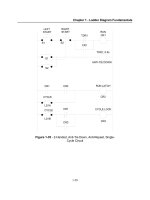
(a)
Typical for
an
LT
motor
s-
1
Speed
c
+
Slip
(b)
Typical for an
HT
motor
4'
N,s
=
0
Figure
1.5
Speed-torque and speed-current curves
at
the
rated
stator voltage
S.
,,e: .
R2
T\,
Dc
s?
,
,\X;
where
T,,
is the torque during start-up or
(1.3a)
and at lower slips or at near the rated speed, when
S
.
,,X?
<<
R2,
equation
(1.3)
will modify to