Tài liệu Sensor Based Intelligent Robots P2 ppt
Bạn đang xem bản rút gọn của tài liệu. Xem và tải ngay bản đầy đủ của tài liệu tại đây (255.36 KB, 10 trang )
Tracking Multiple Moving Objects in Populated, Public Environments 33
There are several improvements for bipartite network flows [2]. However they
require the network to be unbalanced in order to substantially speed up the
algorithms, i.e. either |U||V | or |U||V |, which is not the case in our
context.
The complexity of finding an optimal (minimum or maximum weight) match-
ing might be reduced if the cost label is also a metric on the node set of the
underlying graph. For example if the nodes of the graph are points in the plane
and the cost label is the L
1
(manhattan), L
2
(Euclidean)orL
∞
metric there
are lower time complexity bounds for the problem of finding a minimum weight
perfect matching [15] than in the general case. However it is not obvious if (and
if so, how) this can be applied to the given object correspondence problem.
4 Applications
Fast and robust tracking of moving objects is a versatile ability, which we use
in two applications: detection of obstructions and motion coordination with a
guiding person. In these examples the motion of the robot is controlled by a reac-
tive system that enables it to avoid collisions with static and dynamic obstacles.
More details on this system and the underlying “velocity obstacle” paradigm
can be found in [3,9,11].
4.1 Obstruction Detection
A goal beyond the scope of this paper is to enable a mobile system to recognize
certain situations in its environment. As a first situation we address deliberate
obstructions by humans, people who attempt to stop or bother the mobile sys-
tem. This situation has a certain importance to real world applications of mobile
robots, since systems like these may attract passers-by to experiment on how the
system reacts and controls its motion.
Our detection of obstructions is based on the definition of a supervised area
in front of the robot and three counters assigned to each tracked object. The
supervised area represents the space that the robot needs for its next motion
steps. We call an object blocking if it is situated inside this area but does not
move at a sufficient speed in the robot’s desired direction. The three counters
represent the following values:
1. Number of entrances into supervised area. This is the number of transitions
from non-blocking to blocking state of a tracked object.
2. Duration of current blocking. If the considered object is blocking, the elapsed
time since the last entrance event of this object is counted.
3. Overall duration of blocking. The total time spent blocking by the considered
object is counted.
If any of these counters exceeds a threshold value, the corresponding object is
considered obstructing. Following a dynamic window approach, these counters
forget blockings after a period of time. Note that a passively blocking object is
34 Boris Kluge
evaded by the control scheme, i.e. its relative position leaves the supervised area.
Therefore this counter approach in conjunction with the used control scheme
detects active and deliberate obstructions fairly well.
The same object may be considered obstructing several times. Each time the
response of the system is increased. At first the system informs the object that
it has been tracked and that it interferes with the robot’s motion plan. Next,
the robot stops, asks the obstructor to let it pass by and waits for a short period
of time, hopefully losing the obstructor’s focus of interest. Finally, the robot
might choose an alternative path to its goal to evade this persistent object. In
our current implementation, however, it just gives up.
4.2 Motion Coordination
Objects in the environment are not always opponent to the vehicle. In our second
application one object is accepted as a guide that the robot has to accompany.
This idea is inspired by the implementation on a robotic wheelchair. Typical
applications are a walk in a park, shopping mall or pedestrian area together with
a disabled person. Ideally, there is no need for continuous steering maneuvers, it
is sufficient to indicate the guiding person. This ability to accompany a moving
object is realized by a modification to the underlying velocity obstacle approach.
We give the basic idea here, for further details see [9].
At each step of time the set RV of dynamically reachable velocities of the
vehicle is computed, velocity referring to speed and direction. Omitting veloc-
ities CV causing collisions with moving and static obstacles, an avoidance ve-
locity v is selected for the next cycle from the set RAV = RV \CV of reachable
avoidance velocities. In the original velocity obstacle work, v is selected in order
to reduce the distance to a goal position. In our case the goal is not a position in
the environment but a velocity v
g
which is composed of the velocity of the guide
person, and an additional velocity vector in order to reach a desired position
relative to the guide person. Thus a velocity v is selected from RAV for the
next cycle such that the difference v −v
g
is sufficiently small. So this approach
is of beautiful simplicity but yet powerful enough to enable a robotic vehicle to
accompany a human through natural, dynamic environments, as shown by our
experiments.
5 Experiments
The described system is implemented on a robotic wheelchair equipped with
a SICK laser range finder and a sonar ring [11]. Computations are performed
on an on-board PC (Intel Pentium II, 333 MHz, 64 MB RAM). The laser range
finder is used to observe the environment, whereas the sonar ring helps to avoid
collisions with obstacles that are invisible to the range finder.
The tracking system has been tested in our lab environment and in the
railway station of Ulm. It proved to perform considerably more robust than
its predecessor [10] which is based on a greedy nearest neighbor search among
Tracking Multiple Moving Objects in Populated, Public Environments 35
0
5
10
15
20
25
30
-20 -15 -10 -5 0 5 10 15 20 25
y [m]
x [m]
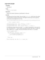
Fig. 3. Outdoor trajectory
the objects’ centers of gravity. The number of objects extracted from a scan
typically ranges from ten to twenty, allowing cycle times of about 50 milliseconds
using the hardware mentioned above. However, the performance of the serial
communication link to the range finder imposes a restriction to three cycles per
second.
Figure 3 shows the trajectory of a guide walking outside on the parking place
in front of our lab. The guide has been tracked and accompanied for 1073 cycles
(more than five minutes), until he finally became occluded to the range finder.
The wheelchair moved counterclockwise. The small loop is caused by the guide
walking around the wheelchair.
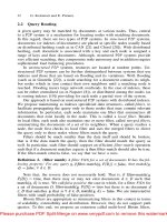
Figure 4 shows trajectories of numerous objects tracked in the railway station
of Ulm. The wheelchair moved from (0, 0) to about (30, −10) accompanying a
guide. Pedestrians’ trajectories crossing the path of the robot or moving parallel
can be seen as well as static obstacles, apparently moving as their centers of
gravity slowly move due to change of perspective and dead reckoning errors.
This scene has been observed for 247 cycles (82 seconds).
6 Further Work
Unfortunately, the tracking system still loses tracked objects occasionally. One
obvious cause is occlusion. It is evident that invisible objects cannot be tracked
by any system. But consider an object occluded by another object passing be-
tween the range finder and the first object. Such an event cancelled the tracking
shown in Fig. 3, where the guide was hidden for exactly one scan. Hence a future
system should be enabled to cope at least with short occlusions.
36 Boris Kluge
-15
-10
-5
0
5
0 5 10 15 20 25 30 3
5
y[m]
x[m]
Fig. 4. Trajectories of objects tracked in the railway station of Ulm
But tracked objects get lost occasionally even if they are still visible. This
might happen for example if new objects appear and old objects disappear si-
multaneously, as the visual field of the range finder is limited. To illustrate this,
imagine a linear arrangement of three objects. Now delete the leftmost object
and insert an object next to the rightmost. A flow computed as described above
induces a false assignment, that is a shift to the right. This problem is partially
dealt with by restriction to a local search for correspondents as presented in
Sect. 3.2. It might be further improved if we do not assign any old object to
new objects that become visible by a change of perspective due to the robot’s
motion.
In some cases object extraction fails to properly split composed objects. If
these objects are recognized separately in the previous scan, either of them is
lost. But this situation may be recognized by looking at the minimum cost flow
in the graph, if there is a significant flow into one node from two predecessors.
This might give a hint to split the newly extracted object.
As object extraction is error-prone, one might follow the idea to compute the
flow based on the scan points before extracting objects by searching for proximity
groups of parallel edges carrying flow. However this might be computationally
infeasible, since the sizes of the graphs involved in the computations of the flows
are heavily increased.
Information about the motion of an object drawn from previous scan images
could be used to compute an approximation of its current position and thus direct
the search for corresponding points. A first implementation of this regarding
the motion of centers of gravity shows poor behaviour in some environments,
for example considering walls moving as their visible part grows. Another bad
effect of position prediction is its tendency to create errors by a chain effect, as
Tracking Multiple Moving Objects in Populated, Public Environments 37
even a single incorrect object assignment results in incorrect prediction of future
positions and therefore may result in further incorrect assignments.
7 Conclusion
In this paper we presented an object tracking system based on laser range finder
images and graph algorithms. The basic idea of our tracking approach is to rep-
resent the motion of object shapes in successive scan images as flows in bipartite
graphs. By optimization (maximum flow, minimum cost, maximum weighted
matching) we get plausible assignments of objects from successive scans. Fur-
thermore, we briefly presented an approach to detect deliberate obstructions of
a robot and a method for motion coordination between a human and a robot.
However, a more robust object extraction and the relatively high computational
complexity of the network flow algorithms remain open problems.
Acknowledgements
This work was supported by the German Department for Education and Re-
search (BMB+F) under grant no. 01 IL 902 F6 as part of the project MORPHA.
References
1. R. K. Ahuja, T. L. Magnati, and J. B. Orlin. Network Flows: Theory, Algorithms,
and Applications. Prentice Hall, 1993.
2. R. K. Ahuja, J. B. Orlin, C. Stein, and R. E. Tarjan. Improved algorithms for
bipartite network flow. SIAM Journal on Computing, 23(5):906–933, Oct. 1994.
3. P. Fiorini and Z. Shiller. Motion planning in dynamic environments using velocity
obstacles. International Journal of Robotics Research, 17(7):760–772, July 1998.
4. E. L. Lawler. Combinatorial optimization: networks and matroids. Rinehart and
Winston, New York, 1976.
5. K. Mehlhorn and S. N¨aher. LEDA—A Platform for Combinatorial and Geometric
Computing. Cambridge University Press, 1999.
6. E. B. Meier and F. Ade. Object detection and tracking in range image sequences
by separation of image features. In IEEE International Conference on Intelligent
Vehicles, pages 280–284, 1998.
7. T. B. Moeslund. Computer vision-based human motion capture – a survey. Tech-
nical Report LIA 99-02, University of Aalborg, Mar. 1999.
8. H. Noltemeier. Graphentheorie: mit Algorithmen und Anwendungen. de Gruyter,
1976.
9. E. Prassler, D. Bank, B. Kluge, and M. Strobel. Coordinating the motion of a
human and a mobile robot in a populated, public environment. In Proc. of Int.
Conf. on Field and Service Robotics (FSR), Helsinki, Finland, June 2001.
10. E. Prassler, J. Scholz, M. Schuster, and D. Schwammkrug. Tracking a large number
of moving objects in a crowded environment. In IEEE Workshop on Perception
for Mobile Agents, Santa Barbara, June 1998.
38 Boris Kluge
11. E. Prassler, J. Scholz, and M. Strobel. Maid: Mobility assistance for elderly and
disabled people. In Proc. of the 24th Int. Conf. of the IEEE Industrial Electronics
Soc. IECON’98, Aachen, Germany, 1998.
12. F. P. Preparata and M. I. Shamos. Computational geometry : an introduction.
Springer Verlag, 1988.
13. S. Roy and I. J. Cox. A maximum-flow formulation of the n-camera stereo corre-
spondence problem. In Proceedings of the International Conference on Computer
Vision, Bombai, Jan. 1998.
14. K. Sobottka and H. Bunke. Vision-based driver assistance using range imagery. In
IEEE International Conference on Intelligent Vehicles, pages 280–284, 1998.
15. P. M. Vaidya. Geometry helps in matching. SIAM Journal on Computing, 18(6):
1201–1225, Dec. 1989.
Omnidirectional Vision
for Appearance-Based Robot Localization
B.J.A. Kr¨ose, N. Vlassis, and R. Bunschoten
Real World Computing Partnership, Novel Functions Laboratory SNN,
Department of Computer Science, University of Amsterdam,
Kruislaan 403, NL-1098 SJ Amsterdam, The Netherlands
{krose,vlassis,bunschot}@science.uva.nl
Abstract. Mobile robots need an internal representation of their envi-
ronment to do useful things. Usually such a representation is some sort
of geometric model. For our robot, which is equipped with a panoramic
vision system, we choose an appearance model in which the sensoric data
(in our case the panoramic images) have to be modeled as a function of
the robot position. Because images are very high-dimensional vectors, a
feature extraction is needed before the modeling step. Very often a lin-
ear dimension reduction is used where the projection matrix is obtained
from a Principal Component Analysis (PCA). PCA is optimal for the
reconstruction of the data, but not necessarily the best linear projection
for the localization task. We derived a method which extracts linear fea-
tures optimal with respect to a risk measure reflecting the localization
performance. We tested the method on a real navigation problem and
compared it with an approach where PCA features were used.
1 Intro duction
An internal model of the environment is needed to navigate a mobile robot opti-
mally from a current state toward a desired state. Such models can be topological
maps, based on labeled representations for objects and their spatial relations, or
geometric models such as polygons or occupancy grids in the task space of the
robot.
A wide variety of probabilistic methods have been developed to obtain a
robust estimate of the location of the robot given its sensory inputs and the en-
vironment model. These methods generally incorporate some observation model
which gives the probability of the sensor measurement given the location of
the robot and the parameterized environment model. Sometimes this parame-
ter vector describes explicit properties of the environment (such as positions of
landmarks [8] or occupancy values [4]) but can also describe an implicit relation
between a sensor pattern and a location (such as neural networks [6], radial basis
functions [10] or look-up tables [2]).
Our robot is equipped with a panoramic vision system. We adopt the implicit
model approach: we are not going to estimate the parameters of some sort of
G.D. Hager et al. (Eds.): Sensor Based Intelligent Robots, LNCS 2238, pp. 39–50, 2002.
c
Springer-Verlag Berlin Heidelberg 2002
40 B.J.A. Kr¨ose, N. Vlassis, and R. Bunschoten
CAD model but we model the relation between the images and the robot location
directly (appearance modeling).
In section 2 we describe how this model is used in a Markov localization
procedure. Then we discuss the problem of modeling in a high dimensional im-
age space and describe the standard approach for linear feature extraction by
Principal Component Analysis (PCA). In order to evaluate the method we need
a criterion, which is discussed in section 5. The criterion can also be used to find
an alternative linear projection: the supervised projection. Experiments on real
robot data are presented in sections 6 and 7 where we compare the two linear
projection methods.
2 Probabilistic Appearance-Based Robot Localization
Let x be a stochastic vector (e.g., 2-D or 3-D) denoting the robot position in
the workspace. Similar to [1] we employ a form of Markov localization for our
mobile robot. This means that at each point in time we have a belief where the
robot is indicated by a probability density p(x). Markov localization requires
two probabilistic models to maintain a good position estimate: a motion model
and an observation model.
The motion model describes the effect a motion command has on the location
of the robot and can be represented by a conditional probability density
p(x
t
|u, x
t−1
) (1)
which determines the distribution of x
t
(the position of the robot after the
motion command u) if the initial robot position is x
t−1
.
The observation model describes the relation between the observation, the
location of the robot, and the parameters of the environment. In our situation
the robot takes an omnidirectional image z at position x. We consider this as a
realization of a stochastic variable z. The observation model is now given by the
conditional distribution
p(z|x; θ), (2)
in which the parameter vector θ describes the distribution and reflects the un-
derlying environment model.
Using the Bayes’ rule we can get an estimate of the position of the robot
after observing z:
p(x|z; θ)=
p(z|x; θ)p(x)
p(z|x; θ)p(x)dx
. (3)
Here p(x) gives the probability that the robot is at x before observing z. Note
that p(x) can be derived using the old information and the motion model
p(x
t
|u, x
t−1
) repeatedly. If both models are known we can combine them and
decrease the motion uncertainty by observing the environment again.
In this paper we will focus on the observation model (2). In order to esti-
mate this model we need a dataset consisting of positions x and corresponding
Omnidirectional Vision for Appearance-Based Robot Localization 41
observations z
1
. We are now faced with the problem of modeling data in a
high-dimensional space, particularly since the dimensionality of z (in our case
the omnidirectional images) is high. Therefore the dimensionality of the sensor
data has to be reduced. Here we restrict ourselves to linear projections, in which
the image can be described as a set of linear features. We will start with a linear
projection obtained from a Principal Component Analyis (PCA), as is usually
done in appearance modeling [5]
3 Principal Component Analysis
Let us assume that we have a set of N images {z
n
}, n =1, ,N. The im-
ages are collected at respective 2-dimensional robot positions {x
n
}. Each image
consists of d pixels and is considered as a d-dimensional data vector. In a Prin-
cipal Component Analysis (PCA) the eigenvectors of the covariance matrix of
an image set are computed and used as an orthogonal basis for representing in-
dividual images. Although, in general, for perfect reconstruction all eigenvectors
are required, only a few are sufficient for visual recognition. These eigenvectors
constitute the q, (q<d) dimensions of the eigenspace. PCA projects the data
onto this space in such a way that the projections of the original data have
uncorrelated components, while most of the variation of the original data set is
preserved.
First we subtract from each image the average image over the entire image
set,
¯
z. This ensures that the eigenvector with the largest eigenvalue represents
the direction in which the variation in the set of images is maximal. We now
stack the N image vectors to form the rows of an N × d image matrix Z. The
numerically most accurate way to compute the eigenvectors from the image set
is by taking the singular value decomposition [7] Z = ULV
T
of the image matrix
Z, where V is a d ×q orthonormal matrix with columns corresponding to the q
eigenvectors v
i
with largest eigenvalues λ
i
of the covariance matrix of Z [3].
These eigenvectors v
i
are now the linear features. Note that the eigenvec-
tors are vectors in the d-dimensional space, and can be depicted as images: the
eigenimages. The elements of the N × q matrix Y = ZV are the projections of
the original d-dimensional points to the new q-dimensional eigenspace and are
the q-dimensional feature values.
4 Observation Model
The linear projection gives us a feature vector y, which we will use for localiza-
tion. The Markov localization procedure, as presented in Section 2, is used on
the feature vector y:
1
In this paper we assume we have a set of positions and corresponding observations:
our method is supervised. It is also possible to do a simultaneous localization and
map building (SLAM). In this case the only available data is a stream of data
{z
(1)
,u
(1)
, z
(2)
,u
(2)
, ,z
(T )
,u
(T )
} in which u is the motion command to the robot.
Using a model about the uncertainty of the motion of the robot it is possible to
estimate the parameters from these data [8].
42 B.J.A. Kr¨ose, N. Vlassis, and R. Bunschoten
p(x|y; θ)=
p(y|x; θ)p(x)
p(y|x; θ)p(x)dx
, (4)
where the denominator is the marginal density over all possible x. We now have
to find a method to estimate the observation model p(y|x; θ) from a dataset
{x
n
, y
n
},n=1, ,N.
We used a kernel density estimation or Parzen estimator. In a Parzen ap-
proach the density function is approximated by a sum of kernel functions over
the N data points from the training set. Note that in a strict sense this is not a
‘parametric’ technique in which the parameters of some pre-selected model are
estimated from the training data. Instead, the training points themselves as well
as the chosen kernel width may be considered as the parameter vector θ.We
write p(y|x; θ)as
p(y|x; θ)=
p(y, x; θ)
p(x; θ)
(5)
and represent each of these distribution as a sum of kernel functions:
p(x, y; θ)=
1
N
N
n=1
g
y
(y − y
n
)g
x
(x − x
n
) (6)
p(x; θ)=
1
N
N
n=1
g
x
(x − x
n
). (7)
where
g
y
(y)=
1
(2π)
q/2
h
q
exp
−
||y||
2
2h
2
and g
x
(x)=
1
2πh
2
exp
−
||x||
2
2h
2
(8)
are the q- and two-dimensional Gaussian kernel, respectively. For simplicity in
our experiments we used the same width h for the g
x
and g
y
kernels.
5 Feature Representation
As is made clear in the previous sections, the performance of the localization
method depends on the linear projection, the number of kernels in the Parzen
model, and the kernel widths. First we discuss two methods with which the
model can be evaluated. Then we will describe how a linear projection can be
found using the evaluation.
5.1 Expected Localization Error
A model evaluation criterion can be defined by the average error between the
true and the estimated position. Such a risk function for robot localization has
been proposed in [9]. Suppose the difference between the true position x
∗
of
the robot and the the estimated position by x is denoted by the loss function