Tài liệu Mold Selection P1 pdf
Bạn đang xem bản rút gọn của tài liệu. Xem và tải ngay bản đầy đủ của tài liệu tại đây (1.83 MB, 12 trang )
113
4 Mold Selection
4.1 Selection of an Appropriate Mold
Once a good product design has been achieved and it is decided where the
product will be made and how many cavities are required, we must consider
the available alternatives for the molds.
4.1.1 Dedicated Mold, Universal Mold Shoe
“Dedicated mold” means a complete mold that is used for one purpose only.
After use, the mold is put into storage until it is used again. This is the most
common type of mold. Occasionally, especially with molds with 2–8 cavities,
the same mold shoe can be and often is used for more than one set of cavities
and cores. In principle, there is nothing wrong with this concept, provided
the molding shop is well organized (good record keeping and proper storage
facilities for the loose stack parts) and the personnel is capable of making
the switch from one product to another without the need for high-priced
mold makers. It may take a few hours to switch from one set of stacks to
another and there is always the risk of damage to the mold components in
handling and during assembly. The question is whether it is worthwhile to
switch molds, especially if it is done frequently. If the mold shoe is quite
simple, it would be better (safer and more economical) to have a dedicated
mold. But there are cases where the mold shoe is large, complicated, and
relatively expensive; if the stacks for the various (preferably similar) products
are designed from the beginning so that they can be easily interchanged, this
is a very good and economical solution.
Typical examples are 4- or 6-cavity molds for a series of round containers,
with none or only small differences in diameters, but with large differences
in height, as would be the case with small tubs for dairy products, e.g., in
sizes from 0.25 liter to 1 liter capacity. Such molds can be designed and built
with all the advantages of a dedicated mold, but saving the cost of several
mold shoes.
“Universal mold shoes” are used mainly for low production runs, for which
only small numbers of cavities are required. They are based on the principle
that stack inserts can be easily and quickly interchanged by the molding
technicians or setup personnel, often even without removing the mold shoe
from the machine. The stacks do not necessarily have to be for the same or
even similar products. They are usually designed for one cavity per insert. If
there is space, two or more cavities and cores could well be placed within
one insert. The disadvantage is that, because the stacks are designed for easy
interchangeability in the mold shoe, it may not be possible to provide them
with the best cooling layouts (facilitating faster cycles) of a dedicated mold.
In addition, the product requiring the longest cooling time governs the cycle
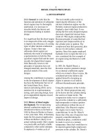
Figure 4.1 A 4-level mold designated to
quickly switch to different sets of inserts
(Courtesy: Stackteck)
Dedicated molds are usually
preferred. However, the use of a
common mold shoe with different
sets of stacks can often be more
economical
For small products and low
quantities, universal molds can often
be the most economical solution
1281han04.pmd 28.11.2005, 11:14113
114
4 Mold Selection
time; however, for low production, short cycle times are not as significant
for the unit cost as is the lower mold cost.
4.1.2 “One-Product” Molds or “Family” Molds?
“One-product mold” is a mold built for one specific product. The best layout
for minimum mold size, space (stack location), cooling, ejection, etc., can be
achieved with a dedicated (one-product) mold.
A “family mold” is a dedicated mold, in which more than one shape of product
is made during the same injection, which will be of the same material and
color. A very serious disadvantage of all family molds is that the cycle time of
the mold is governed by the product (and the mold stack) that is most difficult
to cool. This difference can be substantial, and should be seriously considered,
particularly with products as described in Section 4.1.2.1 and 4.1.2.2. For all
family molds producing pieces of different size, we must make sure that the
mold is laid out so that the clamp forces are balanced as well as possible, i.e.,
that the sum of all projected areas is about equal in each of the 4 mold
quadrants. In other words, the projected areas of the cavities above and below
the horizontal center line of the mold must be nearly equal and so must be
the sum of the projected areas to the right and the left of the vertical center
line of the mold (see Fig. 4.2).
4.1.2.1 Family Molds for Composite Products
For composite products, such as toys and games, it may be desirable to make
all the components of the toy in one shot. Often, the various pieces are kept
on the runner system of a 2-plate mold and are packed and shipped together
with the runner; it is left to the user to take the pieces off the runner during
assembly of the toy. The production runs are usually relatively small; therefore,
this is a most effective method of producing with low cost molds (don’t forget
to include the cost of the runners in the cost of the product).
Occasionally, a product, e.g., a toy car, may have two or more colors. It could
be a car with a blue body, red wheels, and yellow bumpers, etc. By molding
equal production runs of first blue, then red, then yellow parts, 3 sets of cars
can be produced, in the three combinations of colors. In this case, the runners
are not shipped with the product. This method is also used occasionally for
technical products.
4.1.2.2 Family Molds for Small or Medium-Sized Technical
Products
Family molds for small or medium-sized technical products are used when a
number of different sizes of similar, rather small products, such as washers
or seals, are molded in one mold. But such molds can also be used for larger
products, which are required as a “set” in production, as they are used, e.g.,
for home appliances, among others. Any type of mold can be used (hot runner
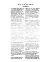
Figure 4.2 Schematic of symmetrically
balanced cavities in relation to the
centerline of the clamp
Figure 4.3 Stack family mold for container
and lid (Courtesy: Husky)
Figure 4.4 Cavity view of 72-cavity cutlery
mold; 24 forks, 24 spoons, and 25 knives are
molded every shot (ca. 8–10 s)
1281han04.pmd 28.11.2005, 11:14114
115
4.1 Selection of an Appropriate Mold
or cold runner, 2-plate or 3-plate). There are two main disadvantages of this
type of mold:
(1) Except for edge-gated 2-plate molds, the products fall out of the mold all
mixed together and must be separated before storage or use.
(2) Stock and production control can have serious problems when some of
the products are used up (e.g., wear) faster than others, and must be
available as spare parts. It may then be necessary to run the mold to
produce the full shots while only some of the items are required. This
problem can be overcome by blocking off the runner system ahead of
the unwanted cavities and running the mold only for the products
required; this means to run the mold less efficiently.
4.1.2.3 Family Molds for Perfect Color Matching
Any plastic, and especially colored plastic, whether colored in-house or bought
already colored from the supplier, comes in batches. Within each batch, the
plastic can be considered uniformly mixed and colored. These batches are
supplied in bags, or in large carboys, or in truckloads, etc. Even though the
specifications to make the batches were identical, there are mixing tolerances
in manufacturing and small variations from batch to batch are unavoidable.
It is better to work with large batches, which will yield large numbers of
matching-colored pieces, but this is not always practical or economical. If a
product pair (or assembly) must have a perfect color match, the answer is to
make the matching pieces in one shot, which is of course supplied by the
same injection unit, at the same time. A typical application for this is a “lady’s
compact”, consisting of a base (for the face powder) and a matching lid (for
the mirror). But there are other applications, some of them in the technical
field. It is quite common to build molds that have the same number of each
of the products that require the perfect color match. If the pieces are required
in pairs and their projected areas are about the same, a mold layout is rather
easy and the stacks can be laid out symmetrically. A problem is that the pieces
are ejected together and must be separated after molding; also, they must
also be stored so that the matching colors are kept together and are not mixed
with products from another color batch (this can also add costs to the
product).
4.1.2.4 Family Molds for In-Mold Assembly
Family molds for in-mold assembly are more sophisticated molds, usually
for very high production volumes and are only rarely used. A multiple of
two different but matching pieces is molded in the same mold; they are
assembled during the ejection time, using special motions, which are part of
the mold or during the mechanical removal (with synchronized take-offs or
robots), so that already assembled pieces are ejected to a conveyor or carried
away under controlled conditions. Such assembly methods may require longer
ejection times but can save subsequent assembly equipment, and time.
Perfect color matching can easily be
achieved with family molds
Figure 4.6 Color matched parts for personal
care products
Figure 4.5 View of ejected array in robot end
of arm tooling
1281han04.pmd 28.11.2005, 11:14115
116
4 Mold Selection
4.1.2.5 Family Molds Using Controlled Ejection for Subsequent
Assembly
This method is almost exclusively used for products where the required annual
quantities are very large and virtually no changes are expected for years. In
these cases, a number of pairs of matching pieces, usually of the same
projected area or with only small difference in area, are molded in one (single
level or stack) mold and then removed either by take-off or by other methods,
which maintain the orientation of the matching pieces so that they can be
easily assembled in a specially designed machine or mechanism, usually
adjacent to the molding machine. Typical examples are Petri dishes, video
and audio- cassettes, CD “jewel boxes,” and so forth.
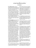
Figure 4.7 shows a Petri dish system taken from the rear of the clamp, which
is protected by guards (A). The bottoms and the tops of the Petri dish are
molded on each face of a 2
× 4, 2 × 6, or 2 × 8 stack mold. Guide rails transport
the molded parts by conveyor (B) to an assembly station (C); from there the
assembled dishes move to a stacker (D) and the stacks of assembled Petri
dishes are then moved to an (open) “sleeving” station (E) where plastic sleeves
are manually pulled over the stacks for boxing and shipping to a sterilizer;
cycle time: 3.5 s, productivity (with 2
× 8 mold): 8,200 assembled dishes/hour.
4.1.3 Where to Gate
The next issue to consider is the location of the gate. The gate is the point
where the plastic enters the cavity space. In some cases, the product designers
will indicate where they believe the gate should be. They may select this
location because of the function and strength of the product and in some
A
B
C
D
E
Figure 4.7 Petri dish system
(Courtesy: Husky)
Figure 4.8 Petri dishes and CD jewel boxes
are typically molded using family molds
Figure 4.9 Cutlery is also often molded
in family molds
1281han04.pmd 28.11.2005, 11:14116
117
cases, because any projecting gate vestige may be bad for appearance or even
harmful to the user. However, such suggested location may not always be the
best for filling the cavity space or for the best strength properties of the
product. At this point of the development, the input by a molder or the mold
designers could be very valuable and a dialogue between the product and
mold designers should be encouraged to find the best location for the gate.
These days, computer aided mold filling simulation packages can accurately
predict the fill patterns of any part. This allows for quick simulations of gate
placements and helps finding the optimal location.
4.1.3.1 Cup- or Box-Shaped Products
In general, for cup- or box-shaped products, outside center gating is most
desirable, because it ensures more evenly distributed flow from the gate
towards the rim or edge. However, center gating (except for single-cavity
molds) implies the use of either 3-plate or hot runner molds, both of which
are more expensive than 2-plate molds. Note that the gate area is always an
area of inherent weakness; molding conditions such as higher melt tempera-
tures, longer molding cycles, and higher cooling temperatures can improve
the strength there and this must be considered as a factor affecting the cycle
time and cost of the product. It should also be noted here that hot runner
valve gating reduces the stresses in the gate area.
The foregoing does not imply that 2-plate molds cannot be used for cup- or
box-shaped products; in fact, 2-plate molds are used for many such products,
but usually only those with larger wall thickness.
4.1.3.2 Flat Products
“Flat” in this context means relatively flat, as opposed to “cup-shaped.” It
includes really flat pieces (in one geometric plane) but also curved products,
such as automotive panels, trays, etc. of all shapes. Flat products are preferably
gated from the edge of the product, because the flow away from the gate (or
gates) will result in a stronger product; it also ensures that there are no
unsightly gate marks in the middle of the product. Here also, it is much better
if the incoming stream of plastic will be directed against a solid portion of
the core or at least a projection of the core and not to flow into an open space,
such as a rib or an open surface. Thin-walled, round products, such as lids
for containers and trays, should be center-gated for faster filling and to reduce
possible distortion when ejected early to gain cycle speed; however, they can
also be edge-gated when the center of the lid must not show a gate mark.
Figure 4.12 shows a selection of typical automotive products. The quantities
are usually small compared with the huge numbers molded for packaging
and medical products and the molds are usually small cavitations (1 or 2).
But even so, most of these products are molded with hot runners, because it
is easier and more effective to control the quality of the products and there is
often less labor required than with cold runner molds. Also, the use of regrind
is sometimes not possible, which makes the justification of a hot runner easier.
Figure 4.12 Selection of typical automotive
products
4.1 Selection of an Appropriate Mold
Figure 4.10 Mold filling analysis is very
useful for finding the best gate location
Figure 4.11 Typical bottom center-gated
parts
1281han04.pmd 28.11.2005, 11:14117
118
4 Mold Selection
Because in most molding machines the injection unit is in line with the center
of the machine platens, it is not possible to edge-gate a single-cavity mold,
unless either there is a large enough opening near the center of the product,
from where a cold or hot runner system can feed one or more edge gates (see
Fig. 4.13), or a hot runner system is used with drops outside of the profile of
the product, feeding into cold runners (see Fig. 4.15).
An alternative is to have the cavity located completely to one side of the
centerline of the machine, which could be possible for any product small
enough to fit there. This however could leave to a severe unbalance in the
clamp. This is not recommended.
There are ways of balancing the clamp forces, e.g., by doubling the size of the
mold and providing a second, similar cavity if the cavity is not too complicated
and expensive, or by adding a pressure pad in a location on the platen
symmetrically opposed to the cavity (see Fig. 4.14). For more details on this
subject, refer to [5] Chapter 6.
If the product is very large, edge-gating into a single cavity can be achieved
with a 3-plate mold (now rarely used for this purpose) or by using a hot
runner system, which enters one or several cold runner systems outside the
edge of the product. From there, cold branch runners can lead to edge or
tunnel gates into the side of the product, just like in a regular 2-plate mold.
This method is used for large, mostly flat products, such as automotive panels,
and so forth (see Fig. 4.15).
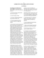
Figure 4.7 shows a flow model of a large automotive panel with three gates
(A) from a hot runner system (B), but without the use of cold runners as in
the schematic of Fig. 4.6. The runners are shown schematically, superimposed
over the photo. Note that here again, the gates are near the edge of the panel
for greater strength.
Figure 4.13 Two examples of gating
into the center of an open product.
The sprue could be a cold sprue or a
hot (runner) sprue
Figure 4.14 Balancing of mold clamp-
ing forces; (left) added second cavity;
(right) added balancing pressure pad
Figure 4.15 Schematic of large, single-cavity
mold with hot runners feeding cold runners;
(a) product (a large panel); (b) sprue; (g) hot
runner channel; (h)”drop” to cold runner;
(j) cold runner; (i) gate
Fill time
= 0.9408 [s]
0.9408
0.7056
0.4704
0.2352
0.0000
[s]
A
A
A
B
Figure 4.16 Flow model of an automotive
panel
1281han04.pmd 28.11.2005, 11:14118
119
4.1.3.3 Deep, Large Cup-Shaped Products
Products in this category are large pails, boxes, garbage containers, large crates,
children’s bathtubs, and so forth. It is always desirable to use one center gate,
if the L/t ratio is low enough (200 or less.) Today’s machines with high
injection pressures have made it even possible to mold large industrial pails
with an L/t ratio of up to 500 with only one gate. However, most large products
(tubs, boxes, etc.) have two or more gates in the bottom for faster, lower-
stress filling and to reduce the L/t ratio for each gate. Large industrial
containers, crates, pallets, etc. may have four or more gates. It is important to
provide venting where the streams coming from the gates are expected to
meet to avoid the risk of air enclosures or even holes at the predicted weld
lines. Such molds with one gate can use a cold sprue (simplest mold) or they
can have a hot sprue. If two or more gates are required, a hot runner system
must be used. 3-plate molds, although theoretically possible, are almost never
used in this arrangement, because of the large size and mass of the cavity
block that would have to move (float) between the moving and stationary
platens to allow ejection of the runner.
Figure 4.17 shows a typical heavy crate (A) for bottles with separators (B)
for individual bottles. This design requires a mold with side cores for the
deep engravings (C) and the openings (D) in the sides. There are also two
baskets (E) with openings (F) in all 4 sides. Because the sides are angled, the
openings can be produced by so-called “shut-offs” between core and cavity
contacting in each opening, thus not requiring side cores. Such a mold is
much less expensive and can cycle much faster than the mold with side cores.
The other picture illustrates a large box (G) with matching, flat snap-on lid
(H).
Figure 4.18 shows 10 and 20 Liter industrial pails. Depending on the ratio of
flow length to wall thickness (L/t ratio), they use either a single gate in the
center or three gates near the rim to facilitate filling.
4.1.3.4 Elongated Products
For maximum strength it is always better to gate near the end of the product
(cold runners) or on the top surface (A) near the end of the product (3-plate
or hot runners). Gating into the top may be undesirable for appearance, but
proper function of the product should always be the first consideration. A gate
mark at the top surface can often be hidden, for example, inside a letter or
and ornament on such surface, or by creating a “fake vestige” in a location
symmetrically opposite the gate (see also Section 2.8.3, Witness Lines).
Figure 4.19 shows typical elongated products (tooth brush, safety razor
handle), which must be gated near the end for maximum strength. Similarly,
other products (not shown), such as cutlery (disposable or not), must also
be gated at the end. If these parts were to be gated in the middle they would
break at the gate.
H
G
F
E
A
B
C
D
Figure 4.17 Typical crates and baskets
Figure 4.18 Very large industrial pails
AAAA
Figure 4.19 Typical elongated products
4.1 Selection of an Appropriate Mold
1281han04.pmd 28.11.2005, 11:14119
120
4 Mold Selection
4.1.3.5 Inside Center Gated Parts
Cold Runner 3-Plate and Hot Runner Molds
In all gate locations mentioned so far, the gate is always located on the outside
(top or side) of the product, i.e., in the hollow (concave) portion of the cavity.
This is good practice because
It is the shortest path for the plastic between the machine nozzle and the
gates
The product will stay with the core from where it can be easily ejected by
any conventional method
The best cooling is on the core where the product shrinks on, to ensure
proper ejection
However, there are cases where a gate on the outside of the product is not
desirable, mostly because of required esthetic appearance. Typically, this is
the case with high-quality closures (for perfume bottle caps, some in-mold
labeled products, etc.) or some spray bottle or over-caps, where a gate
vestige on top would “cheapen” the appearance of the package. But there
are also some technical products and enclosures for which inside gating is
preferred.
Figure 4.20 shows over-caps (A) with inside center gating. It requires long
nozzles (B) and, as can be seen, there is not much space for core cooling.
These molds cycle 2–3 times longer than outside center-gated molds, but
have no gate vestige on the outside. This example shows clearly how little
space there is to provide good cooling, a gate insert, and good heat insulation
from the nozzle tip.
There are some basic drawbacks with inside center gating (ISCG) (see
Fig. 4.21):
The sprue (or drop of a hot runner system) is much longer than with
outside gating to reach the bottom of the product.
Because the cavity is on the moving mold half, the product cannot be
ejected easily. The product will most likely shrink onto and stay with the
core from where it is injected; therefore, an ejection system must be
incorporated into the injection side of the mold and, if necessary, into
the stationary platen of the machine. Ejection by air would be best, but is
often not possible because of the shape of the product and/or the plastic
processed. Therefore, mechanical ejectors (strippers or ejector pins) must
be on the injection side of the mold, which also carries the cores and the
runner system. This ejector system is either air actuated or driven by
mechanical links connected to the moving platen. Most likely, this ejection
mechanism adds still more length to the sprues or drops. These difficulties
are even greater with unscrewing molds, with the cores on the injection
side and the sprue inside the cores.
Figure 4.21 Outside center gated (top),
and inside center gated mold (bottom)
A
B
B
Figure 4.20 Over-caps (A) with inside
center gating (Courtesy: Husky)
1281han04.pmd 28.11.2005, 11:14120
121
The cooling on the inside of any core contributes always more than 60%
of the cooling efficiency of a mold. But with ISCG, inside the core is also
the sprue of a 3-plate system or the drop of a hot runner system. For
shortest molding cycles, we need to cool the core efficiently to remove
the heat both from the product and the sprue in 3-plate molds; however,
in hot runner molds, we must remove the heat from the product while
keeping the hot drop well insulated from the cooled core so that the
plastic in the drop will not freeze. Both these conditions mean that there
is very little space to provide good cooling for the product and much
slower cycles will be unavoidable compared to a similar product gated
from the outside.
The need to provide an ejection system on the injection side makes it
difficult to position the runners and cooling lines in either 3-plate or hot
runner mold. While the moving mold half with the cavities becomes
very simple and relatively small, the injection side with the cores will be
very complicated and large.
With these problems, an ISCG mold is always considerably more complicated
and about 25% more expensive to design and build and will cycle two to
three times slower than a comparable mold with outside gated cavities.
4.1.3.6 Slender Products
Round, thin-walled products such as vials, syringes, etc. are best (outside)
center-gated, using either 3-plate molds or, preferably, hot runner systems,
Fig. 4.22.
Core Shift
Slender products (length over diameter ratio of more than 2.5 : 1) have the
problem of “core shift”; in fact, the core is not shifting but a bending of the
core is caused by differences in the plastic injection pressure. It is practically
impossible to gate exactly concentric between cavity and core; even with the
closest practical tolerances, there will always be some minute misalignment
between the center of the gate (at the closed end) and the center of the cavity
space between the cavity and the core, Fig. 4.23.
Such misalignment will allow more plastic to flow into one side of the core
than into the opposite side and as the cavity space fills, the core will deflect
because of a pressure differential in the plastic between the sides and remain
deflected to some extent until the product is ejected. After ejection, the core
returns (elastically) to its original straightness. The effect of such core
deflection can be measured in the wall thickness but can also be seen easily
by rolling the molded piece on a flat surface; its easily recognizable “banana
shape” is caused by the different shrinkage conditions of the thicker and the
thinner side of the vial (the thicker side takes longer to cool and thus bends
the product after ejection). The thinner the walls are, the worse is the problem
and the more precision in mold making will be required, adding to the cost
Figure 4.22 Gating for vials; (top): center
gating (hot runner or 3-plate); (bottom):
cold runner 2-plate gating. A and B show
top view of gating at 180° and at 120°
4.1 Selection of an Appropriate Mold
1281han04.pmd 28.11.2005, 11:14121
122
4 Mold Selection
of the mold. On the other hand, thicker walls require more plastic (cost!)
and longer cooling (more cost!). When center-gating, there is no problem
with venting because the plastic flows toward the parting line where good
venting is easy to achieve.
To overcome core deflection, there are various methods (some of them
patented) of stabilizing the core inside the cavity and/or selecting a stiffer
core material with a greater modulus of elasticity (E) than mold steel to reduce
the deflection of the core. Some tungsten-carbide alloys exhibit a modulus
of elasticity 2.5 times greater than steel; however, they have little shock
resistance and are expensive to manufacture.
There are mold makers specializing in these products (vials, syringes, pen
barrels, etc.) who have the experience and skills to overcome the problems
and provide good molds.
An older method for making these products is to use cold runner gates (either
self-degating or not) into the side of the barrel (see Fig. 4.22) at or near the
open end, and to use two gates located at 180°, or three gates at 120° around
the circumference of the barrel, or to provide a continuous ring gate all around
the opening. The ring gate will then be machined off. The advantage of any
of these methods is that the plastic enters the cavity space from two or more
symmetrically opposed gates and flows in parallel streams, which tend to
hold the slender core in center. One serious problem with this method is
that the cold runner from the sprue is located in the same plane as the stripper.
Using floating stripper rings is not possible because of the gap required for
floating between the rings and the stripper plate and positioning the stripper
rings exactly in line with the core is very difficult to achieve and very costly.
Still, there are many multi-cavity molds built this way. The second serious
problem with this method is the venting of the air as it is pushed ahead of
the inrushing plastic. With vials, there is no opening at the closed end and
vent pins at the top (dome) are absolutely necessary. A composite cavity,
with a separate part forming the dome will permit vent gaps between the
dome and the cavity portion forming the sides of the vial. Products such as
syringes have a hole in the dome and can be vented there.
Note that uneven filling because the center of the gate is not in line with the
centers of the cavity and the core cannot only happen with slender products
as schematically shown in Figs. 4.22 and 4.23. Figure 4.25 shows a fairly stubby
container with ribs and outside center gating. The lower part of the photo
shows a complete shot. Because the gate is (unintentionally) off-center, the
cavity space fills unevenly, as shown clearly with the 6 short shots, from right
to left. By progressively increasing the shot size it can be clearly seen how the
plastic gradually fills the cavity space and produces an air entrapment that
causes much difficulty when molding.
Figure 4.26 shows the short shot of a thin-walled cap with a “corrugated”
sidewall. The corrugations have slightly different radii in the cavity and on
the core so that the outer tips of the corrugations are somewhat thicker than
the sidewalls, permitting the plastic to flow easier through the thicker tips
Figure 4.24 Typical long slender products
Figure 4.23 Schematic of effect of
misalignment of gate and center of the core
1281han04.pmd 28.11.2005, 11:14122
123
while filling the cavity space. This can be easily seen by the plastic being
father advanced at the tips in the short shot. Note that the mold is almost
perfect, with the advance practically equal all around. This is the result of
very close tolerancing and good workmanship.
Figure 4.27 depicts an over-cap with shallow, flat ribs (A). This is another
example of how the plastic advances faster through heavier sections in the
flow path. To demonstrate and check the filling pattern, the mold was first
injected with clear plastic until it ran at optimal conditions. Then, some yellow
colorant was added to the extruder. When the colored plastic reached the
mold, the front of the incoming melt was still “clear” but the following melt
was already yellow. The plastic advances much faster in the sidewall with the
shallow ribs than in the wall sections between the ribs. These different wall
sections could cause some molding difficulties, if the plastic in the thicker
sections fills so fast that it causes an air entrapment.
4.1.4 Gate Size and Runner Systems
A gate presents a serious restriction to the flow of the plastic; the larger the
gate the easier the cavity can be filled. However, the larger the gate, the more
unsightly will be the gate mark (“vestige”) left on the product. Valve gating
would avoid this problem. In some cases, with certain heat insensitive plastics,
a very small gate could be of advantage by creating so much resistance to the
flow that the shear created will heat the plastic above the melt temperature
and thereby reduce the viscosity of the plastic; this can sometimes help filling
an otherwise difficult-to-fill cavity space. The gate size can be determined by
calculations (see [5], Chapter 10) or by using past experience with similar
products and materials.
Figure 4.25 Stubby container with ribs and
outside center gating
Figure 4.26 Short shot of a thin-walled cap
with a “corrugated” sidewall
Figure 4.27 Over-cap with shallow, flat ribs
4.1 Selection of an Appropriate Mold
1281han04.pmd 28.11.2005, 11:14123
124
4 Mold Selection
The various shapes of gate designs are discussed in detail in [5]. Here, we
will discuss the advantages of certain gates and their influence on productivity.
4.1.4.1 Edge and Fan Gates (Cold Runners)
Both edge and fan gates have been used from the beginning of the injection
molding technology and are still used today. Both gates keep the product
attached to the runner during ejection; the runner must be severed before
using the products.
Edge gates, when properly designed, will break easily at the product and leave
a clean vestige, usually a slightly rough (matte) area the size and shape of the
cross section of the gate. Fan gates leave a very narrow, long vestige that can
be almost invisible. Large edge gates could be required for very large products
or for products that must be molded with a long low-pressure hold cycle to
ensure that the cavity will be fully filled without visible sinks or voids. The
large gates are milled or sawed off, if clipping with pliers is not acceptable for
appearance or if the plastic is too brittle. The cost of this extra operation
must be added to the cost of production. Also, the cost of any jigs or fixtures
required for this purpose must be added to the mold cost. There are a few
occasions where the products should stay connected with the runners:
The products will be shipped with the runners, e.g., with family molds,
when it is of advantage to have the end user remove the products from
the runner when needed.
Very small and delicate products, needing 100% inspection. In this case,
it may be easier to handle the whole array of runners and products from
molding to inspection. This handling and the inspection can also be
automated. Products are degated after inspection.
Oriented packaging into boxes is easier from complete arrays, where the
products (e.g., cutlery) are still in the attitude as they were molded, rather
than being randomly ejected.
4.1.4.2 Self-Degating Cold Runner Gates
The most frequently used self-degating method is tunnel gating (Fig. 4.29).
If the runners and the gates are properly designed and sized, the products
are severed from the runner as the mold starts opening. The molded pieces
and the runners fall out together and must then be separated. There are
automatic separating machines on the market. The gate vestige is small,
usually a round or oval, slightly rough (matte) mark in the side of the product.
If the product is deep enough, there is usually no problem for locating the
gate; if the product is rather shallow, the steel remaining between the gate
and the parting line can be small and fragile and easily be damaged; in this
case, steel selection is very important, but even so, this is an area requiring
frequent repairs. Placing an insert in this area when the mold is built will
save much cost and downtime when the gate is damaged or breaks.
Figure 4.28 Schematics of edge gate (a)
and fan gate (b)
Figure 4.29 Typical tunnel gate
(a)
(b)
1281han04.pmd 28.11.2005, 11:14124
Next Page