Tài liệu Satellite Communications docx
Bạn đang xem bản rút gọn của tài liệu. Xem và tải ngay bản đầy đủ của tài liệu tại đây (5.83 MB, 586 trang )
TLFeBOOK
Satellite
Communications
TLFeBOOK
McGraw-Hill Telecommunications
ALI
●
Digital Switching Systems
A
SH
●
Dynamic Routing in Telecommunications Networks
A
ZZAM/RANSOM
●
Broadband Access Technologies
A
ZZAM
●
High Speed Cable Modems
B
ARTLETT
●
Cable Communications
B
ATES
●
Broadband Telecommunications Handbook
B
ATES
●
Optical Switching and Networking Handbook
B
AYER
●
Computer Telephony Demystified
B
EDELL
●
Wireless Crash Course
C
LAYTON
●
McGraw-Hill Illustrated Telecom Dictionary, Third Edition
C
OLLINS
●
Carrier Class Voice Over IP
D
AVIS
●
ATM for Public Networks
G
ALLAGHER
●
Mobile Telecommunications Networking with IS-41
H
ARTE
●
Cellular and PCS: The Big Picture
H
ARTE
●
CDMA IS-95
H
ARTE
●
GMS Superphones
H
ARTE
●
Delivering xDSL
H
ELDMAN
●
Competitive Telecommunications
M
ACARIO
●
Cellular Radio, Second Edition
M
ULLER
●
Bluetooth Demystified
M
ULLER
●
Desktop Encyclopedia of Telecommunications
M
ULLER
●
Desktop Encyclopedia of Voice and Data Networking
M
ULLER
●
Mobile Telecommunications Factbook
L
ACHS
●
Fiber Optics Communications
L
EE
●
Mobile Cellular Telecommunications, Second Edition
L
EE
●
Mobile Communications Engineering, Second Edition
L
EE
●
Lee’s Essentials of Wireless
L
OUIS
●
Telecommunications Internetworking
P
ATTAN
●
Satelite-Based Cellular Communications
P
ECAR
●
Telecommunications Factbook, Second Edition
R
ICHHARIA
●
Satelite Communications Systems, Second Edition
R
ODDY
●
Satelite Communications, Third Edition
R
OHDE/WHITAKER
●
Communications Receivers, Third Edition
R
USSELL
●
Signaling System #7, Third Edition
R
USSELL
●
Telecommunications Protocols, Second Edition
R
USSELL
●
Telecommunications Pocket Reference
S
HEPARD
●
Telecommunications Convergence
S
HEPARD
●
Optical Networking Demystified
S
IMON
●
Spread Spectrum Communications Handbook
S
MITH
●
Cellular System Design and Optimization
S
MITH
●
Practical Cellular and PCS Design
S
MITH
●
Wireless Telecom FAQs
S
MITH
●
LMDS
T
URIN
●
Digital Transmission Systems
W
INCH
●
Telecommunications Transmission Systems, Second Edition
TLFeBOOK
Satellite
Communications
Dennis Roddy
Third Edition
McGraw-Hill
New York Chicago San Francisco Lisbon London Madrid
Mexico City Milan New Delhi San Juan Seoul
Singapore Sydney Toronto
TLFeBOOK
Copyright © 2001 by The McGraw-Hill Companies, Inc. All rights reserved. Manufactured in the
United States of America. Except as permitted under the United States Copyright Act of 1976, no part
of this publication may be reproduced or distributed in any form or by any means, or stored in a data-
base or retrieval system, without the prior written permission of the publisher.
0-07-138285-2
The material in this eBook also appears in the print version of this title: 0-07-137176-1.
All trademarks are trademarks of their respective owners. Rather than put a trademark symbol after
every occurrence of a trademarked name, we use names in an editorial fashion only, and to the benefit
of the trademark owner, with no intention of infringement of the trademark. Where such designations
appear in this book, they have been printed with initial caps.
McGraw-Hill eBooks are available at special quantity discounts to use as premiums and sales pro-
motions, or for use in corporate training programs. For more information, please contact George
Hoare, Special Sales, at or (212) 904-4069.
TERMS OF USE
This is a copyrighted work and The McGraw-Hill Companies, Inc. (“McGraw-Hill”) and its licensors
reserve all rights in and to the work. Use of this work is subject to these terms. Except as permitted
under the Copyright Act of 1976 and the right to store and retrieve one copy of the work, you may not
decompile, disassemble, reverse engineer, reproduce, modify, create derivative works based upon,
transmit, distribute, disseminate, sell, publish or sublicense the work or any part of it without
McGraw-Hill’s prior consent. You may use the work for your own noncommercial and personal use;
any other use of the work is strictly prohibited. Your right to use the work may be terminated if you
fail to comply with these terms.
THE WORK IS PROVIDED “AS IS”. McGRAW-HILL AND ITS LICENSORS MAKE NO GUAR-
ANTEES OR WARRANTIES AS TO THE ACCURACY, ADEQUACY OR COMPLETENESS OF
OR RESULTS TO BE OBTAINED FROM USING THE WORK, INCLUDING ANY INFORMA-
TION THAT CAN BE ACCESSED THROUGH THE WORK VIA HYPERLINK OR OTHERWISE,
AND EXPRESSLY DISCLAIM ANY WARRANTY, EXPRESS OR IMPLIED, INCLUDING BUT
NOT LIMITED TO IMPLIED WARRANTIES OF MERCHANTABILITY OR FITNESS FOR A
PARTICULAR PURPOSE. McGraw-Hill and its licensors do not warrant or guarantee that the func-
tions contained in the work will meet your requirements or that its operation will be uninterrupted or
error free. Neither McGraw-Hill nor its licensors shall be liable to you or anyone else for any inac-
curacy, error or omission, regardless of cause, in the work or for any damages resulting therefrom.
McGraw-Hill has no responsibility for the content of any information accessed through the work.
Under no circumstances shall McGraw-Hill and/or its licensors be liable for any indirect, incidental,
special, punitive, consequential or similar damages that result from the use of or inability to use the
work, even if any of them has been advised of the possibility of such damages. This limitation of lia-
bility shall apply to any claim or cause whatsoever whether such claim or cause arises in contract, tort
or otherwise.
DOI: 10.1036/0071382852
abc
McGraw-Hill
TLFeBOOK
v
Contents
Preface xiii
Chapter 1. Overview of Satellite Systems 1
1.1 Introduction 1
1.2 Frequency Allocations for Satellite Services 2
1.3 Intelsat 4
1.4 U.S. Domsats 8
1.5 Polar Orbiting Satellites 11
1.6 Problems 19
Chapter 2. Orbits and Launching Methods 21
2.1 Introduction 21
2.2 Kepler’s First Law 21
2.3 Kepler’s Second Law 22
2.4 Kepler’s Third Law 23
2.5 Definitions of Terms for Earth-Orbiting Satellites 24
2.6 Orbital Elements 27
2.7 Apogee and Perigee Heights 29
2.8 Orbital Perturbations 30
2.8.1 Effects of a Nonspherical Earth 30
2.8.2 Atmospheric Drag 35
2.9 Inclined Orbits 36
2.9.1 Calendars 37
2.9.2 Universal Time 38
2.9.3 Julian Dates 39
2.9.4 Sidereal Time 41
2.9.5 The Orbital Plane 42
2.9.6 The Geocentric-Equatorial Coordinate System 46
2.9.7 Earth Station Referred to the IJK Frame 48
2.9.8 The Topocentric-Horizon Coordinate System 53
2.9.9 The Subsatellite Point 57
2.9.10 Predicting Satellite Position 59
2.10 Sun-Synchronous Orbit 60
2.11 Problems 62
Copyright 2001 The McGraw-Hill Companies Click Here for Terms of Use
TLFeBOOK
Chapter 3. The Geostationary Orbit 67
3.1 Introduction 67
3.2 Antenna Look Angles 68
3.3 The Polar Mount Antenna 75
3.4 Limits of Visibility 77
3.5 Near Geostationary Orbits 79
3.6 Earth Eclipse of Satellite 82
3.7 Sun Transit Outage 83
3.8 Launching Orbits 83
3.9 Problems 86
Chapter 4. Radio Wave Propagation 91
4.1 Introduction 91
4.2 Atmospheric Losses 91
4.3 Ionospheric Effects 92
4.4 Rain Attenuation 96
4.5 Other Propagation Impairments 99
4.6 Problems 99
Chapter 5. Polarization 101
5.1 Introduction 101
5.2 Antenna Polarization 105
5.3 Polarization of Satellite Signals 108
5.4 Cross-Polarization Discrimination 113
5.5 Ionospheric Depolarization 115
5.6 Rain Depolarization 116
5.7 Ice Depolarization 118
5.8 Problems 118
Chapter 6. Antennas 121
6.1 Introduction 121
6.2 Reciprocity Theorem for Antennas 122
6.3 Coordinate System 123
6.4 The Radiated Fields 124
6.5 Power Flux Density 128
6.6 The Isotropic Radiator and Antenna Gain 128
6.7 Radiation Pattern 129
6.8 Beam Solid Angle and Directivity 131
6.9 Effective Aperture 132
6.10 The Half-Wave Dipole 133
6.11 Aperture Antennas 134
6.12 Horn Antennas 139
6.13 The Parabolic Reflector 144
6.14 The Offset Feed 149
6.15 Double-Reflector Antennas 150
6.16 Shaped Reflector Systems 154
6.17 Arrays 157
6.18 Problems 161
vi Contents
TLFeBOOK
Chapter 7. The Space Segment 167
7.1 Introduction 167
7.2 The Power Supply 167
7.3 Attitude Control 170
7.3.1 Spinning Satellite Stabilization 172
7.3.2 Momentum Wheel Stabilization 174
7.4 Station Keeping 177
7.5 Thermal Control 179
7.6 TT&C Subsystem 180
7.7 Transponders 181
7.7.1 The Wideband Receiver 183
7.7.2 The Input Demultiplexer 186
7.7.3 The Power Amplifier 186
7.8 The Antenna Subsystem 193
7.9 Morelos 196
7.10 Anik-E 199
7.11 Advanced Tiros-N Spacecraft 200
7.12 Problems 207
Chapter 8. The Earth Segment 209
8.1 Introduction 209
8.2 Receive-Only Home TV Systems 209
8.2.1 The Outdoor Unit 211
8.2.2 The Indoor Unit for Analog (FM) TV 212
8.3 Master Antenna TV System 212
8.4 Community Antenna TV System 213
8.5 Transmit-Receive Earth Stations 214
8.6 Problems 220
Chapter 9. Analog Signals 221
9.1 Introduction 221
9.2 The Telephone Channel 221
9.3 Single-Sideband Telephony 222
9.4 FDM Telephony 224
9.5 Color Television 226
9.6 Frequency Modulation 233
9.6.1 Limiters 234
9.6.2 Bandwidth 234
9.6.3 FM Detector Noise and Processing Gain 237
9.6.4 Signal-to-Noise Ratio 239
9.6.5 Preemphasis and Deemphasis 241
9.6.6 Noise Weighting 243
9.6.7 S/N and Bandwidth for FDM/FM Telephony 243
9.6.8 Signal-to-Noise Ratio for TV/FM 246
9.7 Problems 247
Chapter 10. Digital Signals 251
10.1 Introduction 251
10.2 Digital Baseband Signals 251
Contents vii
TLFeBOOK
10.3 Pulse-Code Modulation 256
10.4 Time-Division Multiplexing 260
10.5 Bandwidth Requirements 261
10.6 Digital Carrier Systems 264
10.6.1 Binary Phase-Shift Keying 266
10.6.2 Quadrature Phase-Shift Keying 268
10.6.3 Transmission Rate and Bandwidth for PSK Modulation 271
10.6.4 Bit Error Rate for PSK Modulation 271
10.7 Carrier Recovery Circuits 277
10.8 Bit Timing Recovery 278
10.9 Problems 279
Chapter 11. Error Control Coding 283
11.1 Introduction 283
11.2 Linear Block Codes 284
11.3 Cyclic Codes 285
11.3.1 Hamming codes 286
11.3.2 BCH codes 286
11.3.3 Reed-Solomon codes 286
11.4 Convolution Codes 289
11.5 Interleaving 292
11.6 Concatenated Codes 293
11.7 Link Parameters Affected by Coding 294
11.8 Coding Gain 296
11.9 Hard Decision and Soft Decision Decoding 297
11.10 Automatic Repeat Request (ARQ) 300
11.11 Problems 302
Chapter 12. The Space Link 305
12.1 Introduction 305
12.2 Equivalent Isotropic Radiated Power 305
12.3 Transmission Losses 306
12.3.1 Free-Space Transmission 307
12.3.2 Feeder Losses 309
12.3.3 Antenna Misalignment Losses 309
12.3.4 Fixed Atmospheric and Ionospheric Losses 310
12.4 The Link Power Budget Equation 311
12.5 System Noise 311
12.5.1 Antenna Noise 313
12.5.2 Amplifier Noise Temperature 314
12.5.3 Amplifiers in Cascade 315
12.5.4 Noise Factor 317
12.5.5 Noise Temperature of Absorptive Networks 318
12.5.6 Overall System Noise Temperature 319
12.6 Carrier-to-Noise Ratio 320
12.7 The Uplink 322
12.7.1 Saturation Flux Density 322
12.7.2 Input Back Off 324
12.7.3 The Earth Station HPA 325
12.8 Downlink 326
12.8.1 Output Back Off 328
12.8.2 Satellite TWTA Output 329
viii Contents
TLFeBOOK
12.9 Effects of Rain 330
12.9.1 Uplink rain-fade margin 331
12.9.2 Downlink rain-fade margin 332
12.10 Combined Uplink and Downlink C/N Ratio 335
12.11 Intermodulation Noise 338
12.12 Problems 340
Chapter 13. Interference 345
13.1 Introduction 345
13.2 Interference between Satellite Circuits (
B
1
and B
2
Modes) 347
13.2.1 Downlink 349
13.2.2 Uplink 350
13.2.3 Combined [C/I] due to interference on both uplink
and downlink 351
13.2.4 Antenna gain function 351
13.2.5 Passband interference 353
13.2.6 Receiver transfer characteristic 354
13.2.7 Specified interference objectives 355
13.2.8 Protection ratio 356
13.3 Energy Dispersal 357
13.4 Coordination 359
13.4.1 Interference levels 360
13.4.2 Transmission gain 361
13.4.3 Resulting noise-temperature rise 362
13.4.4 Coordination criterion 364
13.4.5 Noise power spectral density 364
13.5 Problems 365
Chapter 14. Satellite Access 369
14.1 Introduction 369
14.2 Single Access 370
14.3 Preassigned FDMA 370
14.4 Demand-Assigned FDMA 375
14.5 Spade System 376
14.6 Bandwidth-Limited and Power-Limited TWT Amplifier Operation 379
14.6.1 FDMA Downlink Analysis 379
14.7 TDMA 383
14.7.1 Reference Burst 387
14.7.2 Preamble and Postamble 389
14.7.3 Carrier Recovery 390
14.7.4 Network Synchronization 390
14.7.5 Unique Word Detection 395
14.7.6 Traffic Data 398
14.7.7 Frame Efficiency and Channel Capacity 398
14.7.8 Preassigned TDMA 400
14.7.9 Demand-Assigned TDMA 402
14.7.10 Speech Interpolation and Prediction 403
14.7.11 Downlink Analysis for Digital Transmission 407
14.7.12 Comparison of Uplink Power Requirements for FDMA
and TDMA 408
14.8 On-Board Signal Processing for FDMA/TDM Operation 411
14.9 Satellite-Switched TDMA 414
Contents ix
TLFeBOOK
14.10 Code-Division Multiple Access 417
14.10.1 Direct-sequence spread spectrum 420
14.10.2 The code signal
c(t ) 421
14.10.3 The autocorrelation function for
c(t ) 424
14.10.4 Acquisition and tracking 425
14.10.5 Spectrum spreading and despreading 427
14.10.6 CDMA throughput 428
14.11 Problems 431
Chapter 15. Satellite Services and the Internet 437
15.1 Introduction 437
15.2 Network Layers 438
15.3 The TCP Link 442
15.4 Satellite Links and TCP 443
15.5 Enhancing TCP Over Satellite Channels Using Standard
Mechanisms (RFC-2488) 445
15.6 Requests for Comments 447
15.7 Split TCP Connections 449
15.8 Asymmetric Channels 451
15.9 Proposed Systems 454
15.10 Problems 458
Chapter 16. Direct Broadcast Satellite Services 461
16.1 Introduction 461
16.2 Orbital Spacings 461
16.3 Power Rating and Number of Transponders 463
16.4 Frequencies and Polarization 463
16.5 Transponder Capacity 464
16.6 Bit Rates for Digital Television 465
16.7 MPEG Compression Standards 466
16.8 Forward Error Correction 470
16.9 The Home Receiver Outdoor Unit (ODU) 471
16.10 The Home Reciever Indoor Unit (IDU) 474
16.11 Downlink Analysis 474
16.12 Uplink 482
16.13 Problems 483
Chapter 17. Satellite Services 487
17.1 Introduction 487
17.2 Satellite Mobile Services 488
17.3 VSATs 490
17.4 Radarsat 492
17.5 Global Positioning Satellite System 495
17.6 Orbcomm 498
17.7 Problems 505
Appendix A. Answers to Selected Problems 509
Appendix B. Conic Sections 515
Appendix C. NASA Two-Line Orbital Elements 533
Appendix D. Listings of Artificial Satellites 537
x Contents
TLFeBOOK
Appendix E. Illustrating Third-Order Intermodulation Products 541
Appendix F. Acronyms 543
Appendix G. Logarithmic Units 549
Appendix H. Mathcad Notation 553
References 557
Index 565
Contents xi
TLFeBOOK
This page intentionally left blank.
TLFeBOOK
Preface
In keeping with the objectives of the previous editions, the third edi-
tion is intended to provide broad coverage of satellite communications
systems, while maintaining sufficient depth to lay the foundations for
more advanced studies. Mathematics is used as a tool to illustrate
physical situations and obtain quantitative results, but lengthy math-
ematical derivations are avoided. Numerical problems and examples
can be worked out using a good calculator or any of the excellent math-
ematical computer packages readily available. Mathcad™ is an excel-
lent tool for this purpose and is used in many of the text examples. The
basic Mathcad notation and operations are explained in Appendix H.
In calculating satellite link performance, extensive use is made of
decibels and related units. The reader who is not familiar with some of
the more specialized of these units will find them explained in
Appendix G.
The main additions to the third edition relate to digital satellite ser-
vices. These have expanded rapidly, especially in the areas of Direct
Broadcast Satellite Services (mainly television), and the Internet; new
chapters have been introduced on these topics. Error detection and cor-
rection is an essential feature of digital transmission, and a separate
chapter is given to this topic as well. The section on code-division mul-
tiple access, another digital transmission method, has been expanded.
As in the previous editions, the basic ideas of orbital mechanics are
covered in Chap. 2. However, because of the unique position and
requirements of the geostationary orbit, this subject has been present-
ed in a chapter of its own. Use of non-geostationary satellites has
increased significantly, and some of the newer systems utilizing low
earth orbits (LEOs) and medium earth orbits (MEOs), as proposed for
Internet use, are described. Iridium, a 66 LEO system that had been
designed to provide mobile communications services on a global scale,
declared bankruptcy in 2000 and the service was discontinued. For
xiii
Mathcad is a registered trademark of Mathsoft Inc.
Copyright 2001 The McGraw-Hill Companies Click Here for Terms of Use
TLFeBOOK
this reason, the description of Iridium was not carried through into the
new edition. In December 2000 a new company, Iridium Satellite LLC.,
was formed. Details of the company and the services offered or pro-
posed will be found at Considerable use has
been made of the World Wide Web in updating the previous edition,
and the web sites are referenced in the text. Listings of artificial satel-
lites, previously appended in tabular form, can now be found at the
web sites referenced in Appendix D; these listings have the advantage
of being kept current.
Much of the information in a book of this nature has to be obtained
from companies, professional organizations, and government depart-
ments. These sources are acknowledged in the text, and the author
would like to thank the personnel who responded to his requests for
information. Thanks go to the students at Lakehead University who
suggested improvements and provided corrections to the drafts used
in classroom teaching; to Dr. Henry Driver of Computer Sciences
Corporation who sent in comprehensive corrections and references
for the calculation of geodetic position. The author welcomes
readers’ comments and suggestions and he can be reached by email at
Thanks also go to Carol Levine for the
friendly way in which she kept the editorial process on schedule, and
to Steve Chapman, the sponsoring editor, for providing the impetus to
work on the third edition.
Dennis Roddy
Thunder Bay, Ontario
January 2001
xiv Preface
TLFeBOOK
1
Overview of Satellite Systems
1.1 Introduction
The use of satellites in communications systems is very much a fact of
everyday life, as is evidenced by the many homes which are equipped
with antennas, or “dishes,” used for reception of satellite television.
What may not be so well known is that satellites form an essential
part of telecommunications systems worldwide, carrying large
amounts of data and telephone traffic in addition to television signals.
Satellites offer a number of features not readily available with other
means of communications. Because very large areas of the earth are
visible from a satellite, the satellite can form the star point of a com-
munications net linking together many users simultaneously, users
who may be widely separated geographically. The same feature enables
satellites to provide communications links to remote communities in
sparsely populated areas which are difficult to access by other means.
Of course, satellite signals ignore political boundaries as well as geo-
graphic ones, which may or may not be a desirable feature.
To give some idea of cost, the construction and launch costs of the
Canadian Anik-E1 satellite (in 1994 Canadian dollars) were $281.2
million, and the Anik-E2, $290.5 million. The combined launch insur-
ance for both satellites was $95.5 million. A feature of any satellite sys-
tem is that the cost is distance insensitive, meaning that it costs about
the same to provide a satellite communications link over a short dis-
tance as it does over a large distance. Thus a satellite communications
system is economical only where the system is in continuous use and
the costs can be reasonably spread over a large number of users.
Satellites are also used for remote sensing, examples being the
detection of water pollution and the monitoring and reporting of
weather conditions. Some of these remote sensing satellites also form
Chapter
1
Copyright 2001 The McGraw-Hill Companies Click Here for Terms of Use
TLFeBOOK
a vital link in search and rescue operations for downed aircraft and
the like.
A good overview of the role of satellites is given by Pritchard (1984)
and Brown (1981). To provide a general overview of satellite systems
here, three different types of applications are briefly described in this
chapter: (1) the largest international system, Intelsat, (2) the domestic
satellite system in the United States, Domsat, and (3) U.S. National
Oceanographic and Atmospheric Administration (NOAA) series of
polar orbiting satellites used for environmental monitoring and search
and rescue.
1.2 Frequency Allocations for Satellite
Services
Allocating frequencies to satellite services is a complicated process
which requires international coordination and planning. This is carried
out under the auspices of the International Telecommunication Union.
To facilitate frequency planning, the world is divided into three regions:
Region 1: Europe, Africa, what was formerly the Soviet Union, and
Mongolia
Region 2: North and South America and Greenland
Region 3: Asia (excluding region 1 areas), Australia, and the south-
west Pacific
Within these regions, frequency bands are allocated to various satel-
lite services, although a given service may be allocated different fre-
quency bands in different regions. Some of the services provided by
satellites are
Fixed satellite service (FSS)
Broadcasting satellite service (BSS)
Mobile satellite services
Navigational satellite services
Meteorological satellite services
There are many subdivisions within these broad classifications; for
example, the fixed satellite service provides links for existing tele-
phone networks as well as for transmitting television signals to cable
companies for distribution over cable systems. Broadcasting satellite
services are intended mainly for direct broadcast to the home, some-
times referred to as direct broadcast satellite (DBS) service [in Europe
it may be known as direct-to-home (DTH) service]. Mobile satellite ser-
2 Chapter One
TLFeBOOK
vices would include land mobile, maritime mobile, and aeronautical
mobile. Navigational satellite services include global positioning sys-
tems, and satellites intended for the meterorological services often
provide a search and rescue service.
Table 1.1 lists the frequency band designations in common use for
satellite services. The Ku band signifies the band under the K band,
and the Ka band is the band above the K band. The Ku band is the one
used at present for direct broadcast satellites, and it is also used for
certain fixed satellite services. The C band is used for fixed satellite
services, and no direct broadcast services are allowed in this band. The
VHF band is used for certain mobile and navigational services and for
data transfer from weather satellites. The L band is used for mobile
satellite services and navigation systems. For the fixed satellite ser-
vice in the C band, the most widely used subrange is approximately
4 to 6 GHz. The higher frequency is nearly always used for the uplink
to the satellite, for reasons which will be explained later, and common
practice is to denote the C band by 6/4 GHz, giving the uplink fre-
quency first. For the direct broadcast service in the Ku band, the most
widely used range is approximately 12 to 14 GHz, which is denoted by
14/12 GHz. Although frequency assignments are made much more pre-
cisely, and they may lie somewhat outside the values quoted here (an
example of assigned frequencies in the Ku band is 14,030 and 11,
730 MHz), the approximate values stated above are quite satisfactory
for use in calculations involving frequency, as will be shown later in
the text.
Care must be exercised when using published references to fre-
quency bands because the designations have developed somewhat dif-
ferently for radar and communications applications; in addition, not
all countries use the same designations. The official ITU frequency
Overview of Satellite Systems 3
TABLE 1.1 Frequency Band Designations
Frequency range, GHz Band designation
0.1–0.3 VHF
0.3–1.0 UHF
1.0–2.0 L
2.0–4.0 S
4.0–8.0 C
8.0–12.0 X
12.0–18.0 Ku
18.0–27.0 K
27.0–40.0 Ka
40.0–75 V
75–110 W
110–300 mm
300–3000 m
TLFeBOOK
band designations are shown in Table 1.2 for completeness. However,
in this text the designations given in Table 1.1 will be used, along
with 6/4 GHz for the C band and 14/12 GHz for the Ku band.
1.3 INTELSAT
INTELSAT stands for International Telecommunications Satellite.
The organization was created in 1964 and currently has over 140
member countries and more than 40 investing entities (see
for more details). Starting with the Early
Bird satellite in 1965, a succession of satellites has been launched at
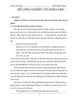
intervals of a few years. Figure 1.1 illustrates the evolution of some of
the INTELSAT satellites. As the figure shows, the capacity, in terms
of number of voice channels, increased dramatically with each suc-
ceeding launch, as well as the design lifetime. These satellites are in
geostationary orbit, meaning that they appear to be stationary in rela-
tion to the earth. The geostationary orbit is the topic of Chap. 3. At this
point it may be noted that geostationary satellites orbit in the earth’s
equatorial plane and that their position is specified by their longitude.
For international traffic, INTELSAT covers three main regions, the
Atlantic Ocean Region (AOR), the Indian Ocean Region (IOR), and
the Pacific Ocean Region (POR). For each region, the satellites are
positioned in geostationary orbit above the particular ocean, where
they provide a transoceanic telecommunications route. The coverage
areas for INTELSAT VI are shown in Fig. 1.2. Traffic in the AOR is
about three times that in the IOR and about twice that in the IOR and
POR combined. Thus the system design is tailored mainly around AOR
requirements (Thompson and Johnston, 1983). As of May 1999, there
were three INTELSAT VI satellites in service in the AOR and two in
service in the IOR.
4 Chapter One
TABLE 1.2 ITU Frequency Band Designations
Frequency range Metric
Band (lower limit exclusive, Corresponding abbreviations
number Symbols upper limit inclusive) metric subdivision for the bands
4 VLF 3–30 kHz Myriametric waves B.Mam
5LF 30–300 kHz Kilometric waves B.km
6 MF 300–3000 kHz Hectometric waves B.hm
7HF 3–30 MHz Decametric waves B.dam
8 VHF 30–300 MHz Metric waves B.m
9 UHF 300–3000 MHz Decimetric waves B.dm
10 SHF 3–30 GHz Centimetric waves B.cm
11 EHF 30–300 GHz Millimetric waves B.mm
12 300–3000 GHz Decimillimetric waves
SOURCE: ITU Geneva.
TLFeBOOK
Figure 1.1 Evolution of INTELSAT satellites. (From Colino 1985; courtesy of ITU Telecommunications Journal.)
5
TLFeBOOK
The INTELSAT VII-VII/A series was launched over a period from
October 1993 to June 1996. The construction is similar to that for the
V and VA/VB series shown in Fig. 1.1 in that the VII series has solar
sails rather than a cylindrical body. This type of construction is
described more fully in Chap. 7. The VII series was planned for service
in the POR and also for some of the less demanding services in the
AOR. The antenna beam coverage is appropriate for that of the POR.
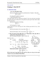
Figure 1.3 shows the antenna beam footprints for the C-band hemi-
spheric coverage and zone coverage, as well as the spot beam coverage
possible with the Ku-band antennas (Lilly, 1990; Sachdev et al., 1990).
When used in the AOR, the VII series satellite is inverted north for
south (Lilly, 1990), minor adjustments then being needed only to opti-
mize the antenna patterns for this region. The lifetime of these satel-
6 Chapter One
Figure 1.2 INTELSAT VI coverage areas. (From P. T. Thompson and E. C. Johnston,
INTELSAT VI: A New Satellite Generation for 1986–2000, International Journal of
Satellite Communications, vol. 1, 3–14. © John Wiley & Sons, Ltd.)
TLFeBOOK
lites ranges from 10 to 15 years depending on the launch vehicle.
Recent figures from the INTELSAT Web site give the capacity for the
INTELSAT VII as 18,000 two-way telephone circuits and 3 TV chan-
nels; up to 90,000 two-way telephone circuits can be achieved with the
use of “digital circuit multiplication.” The INTELSAT VII/A has a
capacity of 22,500 two-way telephone circuits and 3 TV channels; up to
112,500 two-way telephone circuits can be achieved with the use of
digital circuit multiplication. As of May 1999, four satellites were in
service over the AOR, one in the IOR, and two in the POR.
The INTELSAT VIII-VII/A series of satellites was launched over a
period February 1997 to June 1998. Satellites in this series have sim-
ilar capacity as the VII/A series, and the lifetime is 14 to 17 years.
It is standard practice to have a spare satellite in orbit on high-relia-
bility routes (which can carry preemptible traffic) and to have a ground
Overview of Satellite Systems 7
Figure 1.3 INTELSAT VII coverage (Pacific Ocean Region; global, hemispheric, and spot
beams). (From Lilly, 1990, with permission.)
TLFeBOOK
spare in case of launch failure. Thus the cost for large international
schemes can be high; for example, series IX, described below, represents
a total investment of approximately $1 billion.
The INTELSAT IX satellites are the latest in the series (Table 1.3).
They will provide a much wider range of services than previously and
promise such services as Internet, direct-to-home (DTH) TV, tele-
medicine, tele-education, and interactive video and multimedia.
In addition to providing transoceanic routes, the INTELSAT satel-
lites are also used for domestic services within any given country and
regional services between countries. Two such services are Vista for
telephone and Intelnet for data exchange. Figure 1.4 shows typical
Vista applications.
1.4 U.S. Domsats
Domsat is an abbreviation for domestic satellite. Domestic satellites
are used to provide various telecommunications services, such as
voice, data, and video transmissions, within a country. In the United
States, all domsats are situated in geostationary orbit. As is well
known, they make available a wide selection of TV channels for the
home entertainment market, in addition to carrying a large amount of
commercial telecommunications traffic.
U.S. Domsats which provide a direct-to-home television service can
be classified broadly as high power, medium power, and low power
(Reinhart, 1990). The defining characteristics of these categories are
shown in Table 1.4.
The main distinguishing feature of these categories is the equivalent
isotropic radiated power (EIRP). This is explained in more detail in
Chap. 12, but for present purposes it should be noted that the upper
limit of EIRP is 60 dBW for the high-power category and 37 dBW for the
low-power category, a difference of 23 dB. This represents an increase in
received power of 10
2.3
or about 200:1 in the high-power category, which
allows much smaller antennas to be used with the receiver. As noted in
8 Chapter One
TABLE 1.3 INTELSAT Series IX Geostationary Satellites
Satellite Projected location Capacity Launch window
901 62°E Up to 96 units of 36 MHz First quarter 2001
902 60°E Up to 96 units of 36 MHz First quarter 2001
903 335.5°E Up to 96 units of 36 MHz Second quarter 2001
904 342°E Up to 96 units of 36 MHz Third quarter 2001
905 332.5°E Up to 96 units of 36 MHz Fourth quarter 2001 to
first quarter 2002
906 332.5°E Up to 92 units of 36 MHz To be determined
907 328.5°E Up to 96 units of 36 MHz To be determined
TLFeBOOK
Figure 1.4 (a) Typical Vista application; (b) domestic/regional Vista network with standard
A or B gateway. (From Colino, 1985; courtesy of ITU Telecommunication Journal.)
9
TLFeBOOK
the table, the primary purpose of satellites in the high-power category
is to provide a DBS service. In the medium-power category, the primary
purpose is point-to-point services, but space may be leased on these
satellites for the provision of DBS services. In the low-power category,
no official DBS services are provided. However, it was quickly discov-
ered by home experimenters that a wide range of radio and TV pro-
gramming could be received on this band, and it is now considered to
provide a de facto DBS service, witness to which is the large number of
TV receive-only (TVRO) dishes which have appeared in the yards and
on the rooftops of homes in North America. TVRO reception of C-band
signals in the home is prohibited in many other parts of the world, part-
ly for aesthetic reasons because of the comparatively large dishes used,
and partly for commercial reasons. Many North American C-band TV
broadcasts are now encrypted, or scrambled, to prevent unauthorized
access, although this also seems to be spawning a new underground
industry in descramblers.
As shown in Table 1.4, true DBS service takes place in the Ku band.
Figure 1.5 shows the components of a direct broadcasting satellite sys-
tem (Government of Canada, 1983). The television signal may be
relayed over a terrestrial link to the uplink station. This transmits a
very narrowbeam signal to the satellite in the 14-GHz band. The satel-
lite retransmits the television signal in a wide beam in the 12-GHz
frequency band. Individual receivers within the beam coverage area
will receive the satellite signal.
Table 1.5 shows the orbital assignments for domestic fixed satellites
for the United States (FCC, 1996). These satellites are in geostation-
ary orbit, which is discussed further in Chap. 3. Table 1.6 shows the
10 Chapter One
TABLE 1.4 Defining Characteristics of Three Categories of United States
DBS Systems
High power Medium power Low power
Band Ku Ku C
Downlink frequency 12.2–12.7 11.7–12.2 3.7–4.2
allocation, GHz
Uplink frequency allocation, GHz 17.3–17.8 14–14.5 5.925–6.425
Space service BSS FSS FSS
Primary intended use DBS Point to point Point to point
Allowed additional use Point to point DBS DBS
Terrestrial interference possible No No Yes
Satellite spacing, degrees 9 2 2–3
Satellite spacing determined by ITU FCC FCC
Adjacent satellite No Yes Yes
interference possible?
Satellite EIRP range, dBW 51–60 40–48 33–37
ITU: International Telecommunication Union; FCC: Federal Communications Commission.
SOURCE: Reinhart, 1990.
TLFeBOOK