Tài liệu GSM Switching, Services and Protocols P8 pdf
Bạn đang xem bản rút gọn của tài liệu. Xem và tải ngay bản đầy đủ của tài liệu tại đây (834.47 KB, 27 trang )
Roaming and Switching
8.1 Mobile Application Part Interfaces
The main bene®t for the mobile subscribers that the international standardization of GSM
has brought is that they can move freely not only within their home networks but also in
international GSM networks and that at the same time they can even get access to the
special services they subscribed to at home ± provided there are agreements between the
operators. The functions needed for this free roaming are called roaming or mobility
functions. They rely mostly on the GSM-speci®c extension of the Signalling System
Number 7 (SS#7). The Mobile Application Part (MAP) procedures relevant for roaming
are ®rst the Location Registration/Update, IMSI Attach/Detach, requesting subscriber data
for call setup, and paging. In addition, the MAP contains functions and procedures for the
control of supplementary services and handover, for subscriber management, for IMEI
management, for authentication and identi®cation management, as well as for the user data
transport of the Short Message Service. MAP entities for roaming services reside in the
MSC, HLR, and VLR. The corresponding MAP interfaces are de®ned as B (MSC-VLR), C
(MSC-HLR), D (HLR-VLR), E (MSC-MSC), and G (VLR-VLR) (Figure 3.9). At the
subscriber interface, the MAP functions correspond to the functions of Mobility Manage-
ment (MM), i.e. the MM messages and procedures of the Um interface are translated into
the MAP protocols in the MSC.
The most important functions of GSM Mobility Management are Location Registration
with the PLMN and Location Updating to report the current location of an MS, as well as
the identi®cation and authentication of subscribers. These actions are closely interrelated.
During registration into a GSM network, during the location updating procedure, and also
during the setup of a connection, the identity of a mobile subscriber must be determined
and veri®ed (authentication).
The mobility management data are the foundation for creating the functions needed for
routing and switching of user connections and for the associated services. For example,
they are requested for routing an incoming call to the current MSC or for localizing an MS
before paging is started. In addition to mobility data management, information about the
con®guration of supplementary services is requested or changed, e.g. the currently valid
target number for unconditional call forwarding in the HLR or VLR registers.
8
GSM Switching, Services and Protocols: Second Edition. Jo
È
rg Eberspa
È
cher,
Hans-Jo
È
rg Vo
È
gel and Christian Bettstetter
Copyright q 2001 John Wiley & Sons Ltd
Print ISBN 0-471-49903-X Online ISBN 0-470-84174-5
8.2 Location Registration and Location Update
Before a mobile station can be called or gets access to services, the subscriber has to
register with the mobile network (PLMN). This is usually the home network where the
subscriber has a service contract. However, the subscriber can equally register with a
foreign network provider in whose service area he or she is currently visiting, provided
there is a roaming agreement between the two network operators. Registration is only
required if there is a change of networks, and therefore a VLR of the current network has
not yet issued a TMSI to the subscriber. This means the subscriber has to report to the
current network with his IMSI and receives a new TMSI by executing a Location Regis-
tration procedure. This TMSI is stored by the MS in its nonvolatile SIM storage, such that
even after a powerdown and subsequent power-up only a normal Location Updating
procedure is required.
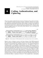
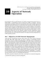
The sequence of operations for registration is presented schematically in Figure 8.1. After
a subscriber has requested registration at his or her current location by sending a location
update request with his or her IMSI and the current location area (LAI), ®rst the MSC
instructs the VLR with a MAP message update location area to register the MS with its
current LAI. In order for this registration to be valid, the identity of the subscriber has to be
checked ®rst, i.e. the authentication procedure is executed. For this purpose, the authenti-
cation parameters have to be requested from the AUC through the HLR. The precalculated
sets of security parameters (Kc, RAND, SRES) are usually not transmitted individually to
the respective VLR. In most cases, several complete sets are kept at hand for several
authentications. Each set of parameters, however, can only be used once, i.e. the VLR
must continually update its supply of security parameters (authentication parameter
request).
After successful authentication (see Section 6.3.2), the subscriber is assigned a new
MSRN, which is stored with the LAI in the HLR, and a new TMSI is also reserved for
this subscriber; this is TMSI Reallocation (see Figure 7.25). To encrypt the user data, the
base station needs the ciphering key Kc, which it receives from the VLR by way of the
MSC with the command start ciphering. After ciphering of the user data has begun, the
TMSI is sent in encrypted form to the mobile station. Simultaneously with the TMSI
assignment, the correct and successful registration into the PLMN is acknowledged (loca-
pdate accept). Finally, the mobile station acknowledges the correct reception of the
TMSI (tmsi reallocation complete, see Figure 7.26).
While the location information is being updated, the VLR is obtaining additional informa-
tion about the subscriber, e.g. the MS category or con®guration parameters for supple-
mentary services. For this purpose, the Insert Subscriber Data Procedure is de®ned
(insert subscriber data message in Figure 8.1). It is used for registration or location
updating in the HLR to transmit the current data of the subscriber pro®le to the VLR. In
general, this MAP procedure can always be used when the pro®le parameters are changed,
e.g. if the subscriber recon®gures a supplementary service such as unconditional forward-
ing. The changes are communicated immediately to the VLR with the Insert Subscriber
Data Procedure.
The location update procedure is executed, if the mobile station recognizes by reading the
LAI broadcast on the BCCH that it is in a new location area, which leads to updating the
8 Roaming and Switching
182
location information in the HLR record. Alternatively, the location update can also occur
periodically, independent of the current location. For this purpose, a time interval value is
broadcast on the BCCH, which prescribes the time between location updates. The main
objective of this location update is to know the current location for incoming calls or short
messages, so that the call or message can be directed to the current location of the mobile
station. The difference between the location update procedure and the location registration
procedure is that in the ®rst case the mobile station has already been assigned a TMSI. The
8.2 Location Registration and Location Update
183
Figure 8.1: Overview of the location registration procedure
TMSI is unique only in connection with an LAI, and both are kept together in the non-
volatile storage of the SIM card. With a valid TMSI, the MS also keeps a current ciphering
key Kc for encryption of user data (Figure 8.2), although this key is renewed during the
location update procedure. This key is recalculated by the MS based on the random
number RAND used for authentication, whereas on the network side it is calculated in
the AUC and made available in the VLR.
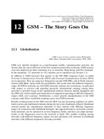
Corresponding to the location update procedure, there is an MM procedure at the air
interface of the MM-category speci®c. Besides the location updating proper, it contains
three blocks which are realized at the air interface by three procedures of the category
common (see Figure 7.26): the identi®cation of the subscriber, the authentication, and the
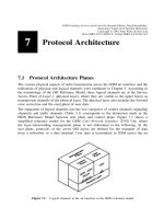
start of ciphering on the radio channel. In the course of location updating, the mobile
station also receives a new TMSI, and the current location is updated in the HLR. Figure
8.2 illustrates the standard case of a location update. The MS has entered a new LA, or the
timer for periodic location updating has expired, and the MS requests to update its location
information. It is assumed that the new LA still belongs to the same VLR as the previous
8 Roaming and Switching
184
Figure 8.2: Overview of the location updating procedure
one, so only a new TMSI needs to be assigned. This is the most frequent case. But if its not
quite so crucial to keep the subscriber identity con®dential, it is possible to avoid assigning
a new TMSI. In this case, only the location information is updated in the HLR/VLR.
The new TMSI is transmitted to the MS in enciphered form together with the acknow-
ledgement of the successful location update. The location update is complete after
acknowledgement by the mobile station. After execution of the authentication, the VLR
can complete its database and replace the ``consumed'' 3-tuple (RAND, SRES, Kc) by
another one requested from the HLR/AUC.
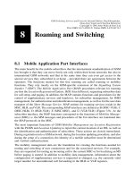
If location change involves both LA and VLR, the location update procedure is somewhat
more complicated (Figure 8.3). In this case, the new VLR has to request the identi®cation
and security data for the MS from the old VLR and store them locally. Only in emergency
cases, if the old VLR cannot be determined from the old LAI or if the old TMSI is not
known in the VLR, the new VLR may request the IMSI directly from the MS (identi®ca-
tion procedure). Only after a mobile station has been identi®ed through the IMSI from the
old VLR and after the security parameters are available in the new VLR, is it possible for
the mobile station to be authenticated and registered in the new VLR, for a new TMSI to be
assigned, and for the location information in the HLR to be actualized. After successful
registration in the new VLR (location update accept) the HLR instructs the old VLR to
cancel the invalid location data in the old VLR (cancel location).
In the examples shown (Figures 8.1±8.3), the location information is stored as MSRN in
the HLR. The MSRN contains the routing information for incoming calls and this infor-
8.2 Location Registration and Location Update
185
Figure 8.3: Location update after changing the VLR area
mation is used to route incoming calls to the current MSC. In this case, the HLR receives
the routing information already at the time of the location update. Alternatively, at location
update time, the HLR may just store the current MSC and/or VLR number in connection
with an LMSI, such that routing information is only determined at the time of an incoming
call.
8.3 Connection Establishment and Termination
8.3.1 Routing Calls to Mobile Stations
The number dialed to reach a mobile subscriber (MSISDN) contains no information at all
about the current location of the subscriber. In order to establish a complete connection to a
mobile subscriber, however, one must determine the current location and the locally
responsible switch (MSC). In order to be able to route the call to this switch, the routing
address to this subscriber (MSRN) has to be obtained. This routing address is assigned
temporarily to a subscriber by its currently associated VLR. At the arrival of a call at the
GMSC, the HLR is the only entity in the GSM network which can supply this information,
and therefore it must be interrogated for each connection setup to a mobile subscriber. The
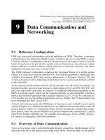
principal sequence of operations for routing to a mobile subscriber is shown in Figure 8.4.
An ISDN switch recognizes from the MSISDN that the called subscriber is a mobile
subscriber, and therefore can forward the call to the GMSC of the subscriber's home
PLMN based on the CC and NDC in the MSISDN (1). This GMSC can now request the
current routing address (MSRN) for the mobile subscriber from the HLR using the MAP
(2,3). By way of the MSRN the call is forwarded to the local MSC (4), which determines
the TMSI of the subscriber (5,6) and initiates the paging procedure in the relevant location
area (7). After the mobile station has responded to the paging call (8), the connection can
be switched through.
Several variants for determining the route and interrogating the HLR exist, depending on
how the MSRN was assigned and stored, whether the call is national or international, and
depending on the capabilities of the associated switching centers.
8.3.1.1 Effect of the MSRN Assignment on Routing
There are two ways to obtain the MSRN:
² obtaining the MSRN at location update
² obtaining the MSRN on a per call basis
For the ®rst variant, an MSRN for the mobile station is assigned at the time of each location
update which is stored in the HLR. This way the HLR is in a position to supply immedi-
ately the routing information needed to switch a call through to the local MSC.
The second variant requires that the HLR has at least an identi®cation for the currently
responsible VLR. In this case, when routing information is requested from the HLR, the
HLR ®rst has to obtain the MSRN from the VLR. This MSRN is assigned on a per call
basis, i.e. each call involves a new MSRN assignment.
8 Roaming and Switching
186
8.3.1.2 Placement of the Protocol Entities for HLR Interrogation
Depending on the capabilities of the associated switches and the called target (national or
international MSISDN), there are different routing procedures. In general, the local switch-
ing center analyzes the MSISDN. Due to the NDC, this analysis of the MSISDN allows the
separation of the mobile traf®c from other traf®c. The case that mobile call numbers are
integrated into the numbering plan of the ®xed network is currently not provided.
In the case of a national number, the local exchange recognizes from the NDC that the
number is a mobile ISDN number. The ®xed network and home PLMN of the called
subscriber reside in the same country. In the ideal case, the local switch can interrogate
the HLR responsible for this MSISDN (HLR in the home PLMN of the subscriber) and
obtain the routing information (Figure 8.5a). The connection can then be switched through
via ®xed connections of the ISDN directly to the MSC.
If the local exchange does not have the required protocol intelligence for the interrogation
of the HLR, the connection can be passed on preliminarily to a transit exchange, which
then assumes the HLR interrogation and routing determination to the current MSC (Figure
8.5b). If the ®xed network is not at all capable of performing an HLR interrogation, the
connection has to be directed through a GMSC. This GMSC connects through to the
current MSC (Figure 8.5c). For all three cases, the mobile station could also reside in a
foreign PLMN (roaming); the connection is then made through international lines to the
current MSC after interrogating the HLR of the home PLMN.
In the case of an international call number, the local exchange recognizes only the
international CC and directs the call to an International Switching Center (ISC). Then
the ISC can recognize the NDC of the mobile network and process the call accordingly.
Figures 8.6 and 8.7 show examples for the processing of routing information. An inter-
8.3 Connection Establishment and Termination
187
Figure 8.4: Principle of routing calls to mobile subscribers
national call to a mobile subscriber involves at least three networks: the country from
which the call originates; the country with the home PLMN of the subscriber, Home
PLMN (H-PLMN); and the country in which the mobile subscriber is currently roaming,
Visited PLMN (V-PLMN). The traf®c between countries is routed through ISCs. Depend-
ing on the capabilities of the ISC, there are several routing variants for international calls
to mobile subscribers. The difference is determined by the entity that performs the HLR
interrogation, resulting in differently occupied line capacities.
8 Roaming and Switching
188
Figure 8.5: Routing variants for national MSISDN
Figure 8.6: Routing for international MSISDN (HLR interrogation from ISC)
If the ISC performs the HLR interrogation, the routing to the current MSC is performed
either by the ISC of the originating call or by the ISC of the mobile subscriber's H-PLMN
(Figure 8.6). If no ISC can process the routing, again a GMSC has to get involved, either a
GMSC in the country where the call originates or the GMSC of the H-PLMN (Figure 8.7).
For the routing procedures explained here, it does not matter which kind of subscriber is
calling, i.e. the subscriber may be in the ®xed network or in the mobile network. However,
for calls from mobile subscribers, the HLR interrogation is usually performed at the local
exchange (MSC).
8.3.2 Call Establishment and Corresponding MAP Procedures
Call establishment in GSM at the air interface is similar to ISDN call establishment at the
user network interface (Q.931) [7]. The procedure is supplemented by several functions:
random access to establish a signaling channel (SDCCH) for call setup signaling, the
authentication part, the start of ciphering, and the assignment of a radio channel.
The establishment of a connection always contains a veri®cation of user identity (authen-
tication) independent of whether it is a mobile-originated call setup or a mobile-terminated
call setup. The authentication is performed in the same way as for location updating. The
VLR supplements its database entry for this mobile station with a set of security data,
which replaces the ``consumed'' 3-tuple (RAND, SRES, Kc). After successful authentica-
tion, the ciphering process for the encryption of user data is started.
8.3.2.1 Outgoing Connection Setup
For outgoing connection setup (Figure 8.8), ®rst the mobile station announces its connec-
8.3 Connection Establishment and Termination
189
Figure 8.7: Routing through GMSC for international MSISDN
tion request to the MSC with a setup indication message, which is a pseudo-message. It
is generated between the MM entity of the MSC and the MAP entity, when the MSC
receives the message cm-service request from the MS, which indicates in this way the
request for an MM connection (see Figure 7.27). Then the MSC signals to the VLR that the
mobile station identi®ed by the temporary TMSI in the location area LAI has requested
service access (process access request) which is an implicit request for a random
number RAND from the VLR, to be able to start the authentication of the MS. This random
number is transmitted to the mobile station, its response with authentication result SRES is
returned to the VLR, which now examines the authenticity of the mobile station's identity
(compare authentication at registration, Figure 8.1).
After successful authentication, the ciphering process is started on the air interface, and
this way the MM connection between MS and MSC has been completely established (cm-
service accept). Subsequently, all signaling messages can be sent in encrypted form.
Only now the MS reports the desired calling target. While the MS is informed with a call
8 Roaming and Switching
190
Figure 8.8: Overview of outgoing call setup
proceeding message that processing of its connection request has been started, the MSC
reserves a channel for the conversation and assigns it to the MS (assign). The connection
request is signaled to the remote network exchange through the signaling system SS#7
with the ISDN User Part (ISUP) message iam [7]. When the remote exchange answers
(acm), the delivery of the call can be indicated to the mobile station (alert). Finally, when
the called partner goes off-hook, the connection can be switched through (connect, ans,
connect acknowledge).
8.3.2.2 Incoming Connection Setup
For incoming connection setup, it is necessary to determine the exact location of an MS in
order to route the call to the currently responsible MSC. A call to a mobile station is
therefore always routed to an entity which is able to interrogate the HLR for temporary
routing information and to use it to forward the call. Usually, this entity is a GMSC of the
home PLMN of the MS (see Section 8.3.1.2). Through this HLR interrogation, the GMSC
obtains the current MSRN of the mobile station and forwards it to the current MSC (Figure
8.9).
Depending on whether the MSRN is stored in the HLR or ®rst has to be obtained from the
VLR, two variants of the HLR interrogation exist. In the ®rst case, the interrogated HLR
can supply the MSRN immediately (routing information). In the second case, the HLR
8.3 Connection Establishment and Termination
191
Figure 8.9: Interrogation of routing information for incoming call
has only received and stored the current VLR address during location update. Therefore,
the HLR ®rst has to request the current routing information from the VLR before the call
can be switched through to the local MSC.
Call processing is interrupted again in the local MSC in order to determine the exact
location of the mobile station within the MSC area (send info for setup, Figure 8.10).
The current LAI is stored in the location registers, but an LA can comprise several cells.
Therefore, a broadcast (paging call) in all cells of the LA is used to determine the exact
location, i.e. cell, of the MS. Paging is initiated from the VLR using the MAP (page ms)
and transformed by the MSC into the paging procedure at the air interface. When an MS
receives a paging call, it responds directly and thus allows determination of the current
cell.
8 Roaming and Switching
192
Figure 8.10: Overview of incoming call setup
Thereafter, the VLR instructs the MSC to authenticate the MS and to start ciphering on the
signaling channel. Optionally, the VLR can execute a reallocation of the TMSI (TMSI
reallocation procedure) during call setup. Only at this point, after the network internal
connection has been established (see Section 7.4.4), the connection setup proper can be
processed (command complete call from VLR to MSC). The MS is told about the
connection request with a setup message, and after answering call complete it receives
a channel. After ringing (alert) and going off-hook, the connection is switched through
connect, connect, acknowledge), and this fact is also signaled to the remote exchange
(acm, ans).
8.3.3 Call Termination
At the air interface, a given call can be terminated either by the mobile equipment or by the
network. The taking down of the connection is initiated at the Um interface by means of
the CC messages disconnect, release, and release complete. This is followed by an
explicit release of occupied radio resources (channel release). On the network side, the
connection between the involved switching centers (MSC, etc.) is terminated using the
ISUP messages rel and rlc in the SS#7 network (Figure 8.11).
After taking down of the connection, information about charges (charging information)
is stored in the VLR or HLR using the MAP. This charging data can also be required for an
incoming call, e.g. if roaming charges are due because the called subscriber is not in his or
her home PLMN.
8.3.4 MAP Procedures and Routing for Short Messages
A connectionless relay protocol has been de®ned for the transport of short messages (see
Section 7.4.8) at the air interface, which has a counterpart in the network in a store-and-
forward operation for short messages. This forwarding of transport PDUs of the SMS uses
MAP procedures. For an incoming short message which arrives from the Short Message
Service Center (SMS-SC) at a Short Message Gateway MSC (SMS-GMSC), the exact
location of the MS is the ®rst item that needs to be determined just as for an incoming
call. The current MSC of the MS is ®rst obtained with an HLR interrogation (short
8.3 Connection Establishment and Termination
193
Figure 8.11: Mobile-initiated call termination and storing of charging information
message routing information, Figure 8.12a). The short message is then passed to this
MSC (forward short message) and is locally delivered after paging and SMS connec-
tion setup. Success or failure are reported to the SMS-GMSC in another MAP message
(forward acknowledgement/error indication) which then informs the service
center.
In the reverse case, for an outgoing short message, no routing interrogation is needed, since
the SMS-GMSC is known to all MSC, so the message can be passed immediately to the
SMS-GMSC (Figure 8.12b).
8.4 Handover
8.4.1 Overview
Handover is the transfer of an existing voice connection to a new base station. There are
different reasons for the handover to become necessary. In GSM, a handover decision is
made by the network, not the mobile station, and it is based on BSS criteria (received
signal level, channel quality, distance between MS and BTS) and on network operation
criteria (e.g. current traf®c load of the cell and ongoing maintenance work).
The functions for preparation of handover are part of the Radio Subsystem Link Control.
Above all, this includes the measurement of the channel. Periodically, a mobile station
checks the signal ®eld strength of its current downlinks as well as those of the neighboring
base stations, including their BSICs. The MS sends measurement reports to its current base
station (quality monitoring); see Section 5.5.1. On the network side, the signal quality of
the uplink is monitored, the measurement reports are evaluated, and handover decisions
are made.
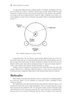
As a matter of principle, handovers are only performed between base stations of the same
PLMN. Handovers between BSS in different networks are not allowed. Two kinds of
handover are distinguished (Figure 8.13):
² Intracell Handover: for administrative reasons or because of channel quality (channel-
selective interferences), the mobile station is assigned a new channel within the same
cell. This decision is made locally by the Radio Resource Management (RR) of the BSS
and is also executed within the BSS.
² Intercell Handover: the connection to an MS is transferred over the cell boundary to a
new BTS. The decision about the time of handover is made by the RR protocol module
of the network based on measurement data from MS and BSS. The MSC, however, can
participate in the selection of the new cell or BTS. The intercell handover occurs most
often when it is recognized from weak signal ®eld strength and bad channel quality
(high bit error ratio) that a mobile station is moving near the cell boundary. However, an
intercell handover can also occur due to administrative reasons, say for traf®c load
balancing. The decision about such a network-directed handover is made by the
MSC, which instructs the BSS to select candidates for such a handover.
Two cases need to be distinguished with regard to participation of network components in
the handover, depending on whether the signaling sequences of a handover execution also
8 Roaming and Switching
194
involve an MSC. Since the RR module of the network resides in the BSC (see Figure 7.11),
the BSS can perform the handover without participation of the MSC. Such handovers
occur between cells which are controlled by the same BSC and are called internal hand-
over. They can be performed independently by the BSS; the MSC is only informed about
the successful execution of internal handovers. All other handovers require participation of
at least one MSC, or their BSSMAP and MAP parts, respectively. These handovers are
known as external handovers.
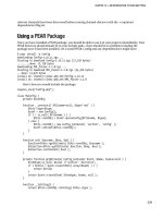
Participating MSCs can act in the role of MSC-A or MSC-B. MSC-A is the MSC which
8.4 Handover
195
Figure 8.12: Forwarding short messages in a PLMN
performed the initial connection setup, and it keeps the MSC-A role and complete control
(anchor MSC) for the entire life of the connection. A handover is therefore in general the
extension of the connection from the anchor MSC-A to another MSC (MSC-B). In this
case, the mobile connection is passed from MSC-A to MSC-B with MSC-A keeping the
ultimate control over the connection. An example is presented in Figure 8.14. A mobile
station occupies an active connection via BTS1 and moves into the next cell. This cell of
BTS2 is controlled by the same BSC so that an internal handover is indicated. The
connection is now carried from MSC-A over the BSC and the BTS2 to the mobile station;
the connections of BTS1 (radio channel and ISDN channel between BTS and BSC) were
taken down. As the mobile station moves on to the cell handled by BTS3, it enters a new
BSS which requires an external handover. Besides, this BSS belongs to another MSC,
which now has to play the role of MSC-B. Logically, the connection is extended from
MSC-A to MSC-B and carried over the BSS to the mobile station. At the next change of
the MSC, the connection element between MSC-A and MSC-B is taken down, and a
8 Roaming and Switching
196
Figure 8.13: Intracell and intercell handover
Figure 8.14: Internal and external handover
connection to the new MSC from MSC-A is set up. Then the new MSC takes over the role
of MSC-B.
8.4.2 Intra-MSC Handover
The basic structure for an external handover is the handover between two cells of the same
MSC (Figure 8.15). The mobile station continually transmits measurement reports with
channel monitoring data on its SACCH to the current base station (BSS 1). Based on these
measurement results, the BSS decides when to perform a handover and requests this
handover from the MSC (message handover required). The respective measurement
results can be transmitted in this message to the MSC, to enable its participation in the
handover decision. The MSC causes the new BSS to prepare a channel for the handover,
and frees the handover to the mobile station (handover command), as soon as the
reservation is acknowledged by the new BSS. The mobile station now reports to the
new BSS (handover access) and receives information about the physical channel proper-
ties. This includes synchronization data like the new timing advance value and also the
new transmitter power level. Once the mobile station is able to occupy the channel
successfully, it acknowledges this fact with a message handover complete. The
resources of the old BSS can then be released.
8.4.3 Decision Algorithm for Handover Timing
The basis for processing a successful handover is a decision algorithm which uses
measurement results from mobile and base station to identify possible other base stations
as targets for handovers and which determines the optimal moment to execute the hand-
over. The objective is to keep the number of handovers per cell change as small as possible.
Ideally, there should not be more than one handover per cell change. In reality, this is often
not achievable. When a mobile station leaves the radio range of a base station and enters
one of a neighboring station, the radio conditions are often not very stable, so that several
handovers must be executed before a stable state is reached. Simulation results in [44] and
[36] give a mean value of about 1.5±5 handovers per cell change.
Since every handover incurs not only increased traf®c load for the signaling and transport
system but also reductions in speech quality, the importance of a well-dimensioned hand-
over decision algorithm is obvious, an algorithm which also takes into account the momen-
tary local conditions. This is also a reason for GSM not having standardized a uniform
algorithm for the determination of the moment of the handover. For this decision about
when to perform a handover, network operators can develop and deploy their own algo-
rithms which are optimally tuned for their networks. This is made possible through stan-
dardizing only the signaling interface that de®nes the processing of the handover and
through transferring the handover decision to the BSS. The GSM handover is thus a
network-originated handover as opposed to a mobile-originated handover, where the
handover decision is made by the mobile station. An advantage of this handover approach
is that the software of the mobile station need not be changed when the handover strategy
or the handover decision algorithm is changed in all or parts of the network. Even though
the GSM standard does not prescribe a mandatory handover decision algorithm, a simple
8.4 Handover
197
algorithm is proposed, which can be selected by the network operator or replaced by a
more complex algorithm.
In principle, a GSM handover always proceeds in three steps (Figure 8.16), which are
based on the measurement data provided by the mobile station over the SACCH, and on
the measurements performed by the BSS itself. Foremost among these data items are the
current channel's received signal level (RXLEV) and the signal quality (RXQUAL), both
on the uplink (measured by the BSS) and on the downlink (measured by the MS). In order
to be able to identify neighboring cells as potential targets for a handover, the mobile
station measures in addition the received signal level RXLEV_CELL(n)ofupto16
8 Roaming and Switching
198
Figure 8.15: Principal signaling sequence for an intra-MSC handover
Figure 8.16: Decision steps in a GSM handover
neighboring base stations. The RXLEV values of the six base stations which can be
received best are reported every 480 ms to the BSS. Further criteria for the handover
decision algorithm are the distance between MS and BTS measured via the Timing
Advance (TA) of the Adaptive Frame Alignment (see Section 5.3.2) and measurements
of the interference in unused time slots. A new value of each of these measurements is
available every 480 ms.
Measurement preprocessing calculates average values from these measurements, whereby
at least the last 32 values of RXLEV and RXQUAL must be averaged. The resulting mean
values are continuously compared with thresholds (see Table 8.1) after every SACCH
interval.
These threshold values can be con®gured individually for each BSS through management
interfaces of the OMSS (see Section 3.3.4). The principle used for the comparison of
measurements with the threshold is to conduct a so-called Bernoulli experiment: if out
of the last N
i
mean values of a criterion i more than P
i
go under (RXLEV) or over
(RXQUAL, MS_RANGE) the threshold, then a handover may be a necessary. The values
of N
i
and P
i
can also be con®gured through network management. Their allowed range is
de®ned as the interval [0; 31].
In addition to these mean values, a BSS can calculate the current power budget PBGT(n),
which represents a measure for the respective path loss between mobile station and current
base station or a neighboring base station n. Using this criterion, a handover can always be
caused to occur to the base station with the least path loss for the signals from or to the
mobile station. The PBGT takes into consideration not only the RXLEV_DL of the current
downlink and the RXLEV_NCELL(n) of the neighboring BCCH but also the maximal
transmitter power P (see Table 5.8) of a mobile station, the maximal power
MS_TXPWR_MAX allowed to a mobile station in the current cell, and the maximal
power MS_TXPWR_MAX(n) allowed to mobiles in the neighboring cells. In addition,
the calculation uses the value PWR_C_D, which is the difference between maximal
transmitter power on the downlink and current transmitter power of the BTS in the down-
link, a measure for the available power control reserve.
Thus the power budget for a neighboring base station n is calculated as follows:
PBGTnMinimum MS_TXPWR_MAX; P 2 RXLEV_DL 2 PWR_C_D
2 Minimum MS_TXPWR_MAXn; P 2 RXLEV_NCELLn
A handover to a neighboring base station can be requested, if the power budget is
PBGT(n) . 0 and greater than the threshold HO_MARGIN(n). The causes for handover
which are possible using these criteria are summarized in Table 8.2. As can be seen, the
signal criteria of the uplink and downlink as well as the distance from the base station and
power budget can lead to a handover.
The BSS makes a handover decision by ®rst determining the necessity of a handover using
the threshold values of Table 8.1. In principle, one can distinguish three categories:
² Handover because of more favorable path loss conditions
² Mandatory intercell handover
² Mandatory intracell handover
8.4 Handover
199
Situations where a neighboring base station shows more favorable propagation conditions
and therefore lower path loss, do not necessarily force a handover. Such potential handover
situations to a neighboring cell are discovered through the PBGT(n) calculations. To make
a handover necessary, the power budget of the neighboring cell must be greater than the
threshold HO_MARGIN(n).
The recognition of a mandatory handover situation (Figure 8.17) within the framework of
8 Roaming and Switching
200
Table 8.1 Threshold values for the GSM handover
Threshold value Typical value Meaning
L_RXLEV_UL_H 2103 to 273 dBm Upper handover threshold of received
signal level in uplink
L_RXLEV_DL_H 2103 to 273 dBm Upper handover threshold of received
signal level in downlink
L_RXLEV_UL_IH 285 to 240 dBm Lower(!) received signal level threshold in
uplink for internal handover
L_RXLEV_DL_IH 285 to 240 dBm Lower(!) received signal level threshold in
downlink for internal handover
RXLEV_MIN(n) approx. 285 dBm Minimum required RXLEV of BCCH of cell
n to perform a handover to this cell
L_RXQUAL_UL_H ± Lower handover threshold of bit error ratio
in uplink
L_RXQUAL_DL_H ± Lower handover threshold of bit error ratio
in downlink
MS_RANGE_MAX 2 to 35 km Maximum distance between mobile and
base station
HO_MARGIN(n) 0 to 24 dB Hysteresis to avoid multiple handovers
between two cells
Table 8.2 Handover causes
Handover cause Meaning
UL_RXLEV Uplink received signal level too low
DL_RXLEV Downlink received signal level too low
UL_RXQUAL Uplink bit error ratio too high
DL_RXQUAL Downlink bit error ratio too high
PWR_CTRL_FAIL Power control range exceeded
DISTANCE MS to BTS distance too high
PBGT(n) Lower value of path loss to BTS n
the Radio Subsystem Link Control (see also Section 5.5 and Figure 5.19) is based on the
received signal level and signal quality in uplink and downlink as well as on the distance
between MS and BTS. Going over or under the respective thresholds always necessitates a
handover. Here are the typical situations for a mandatory handover:
² The received signal level in the uplink or downlink (RXLEV_UL/RXLEV_DL) drops
below the respective handover threshold value (L_RXLEV_UL_H/L_RXLEV_DL_H)
and the power control range has been exhausted, i.e. the MS and/or the BSS have
reached their maximal transmitter power (see Section 5.5.2).
² The bit error ratio as a measure of signal quality in uplink and/or downlink (RXQUAL_
UL/RXQUAL_DL) exceeds the respective handover threshold value (L_RXQUAL_
8.4 Handover
201
Figure 8.17: Detection of mandatory handover (abbreviated)
UL_H/L_RXQUAL_DL_H), while at the same time the received signal level drops into
the neighborhood of the threshold value.
² The maximum distance to the base station (MAX_MS_RANGE) has been reached.
A handover can also become mandatory, even if the handover thresholds are not exceeded,
if the lower thresholds of the transmitter power control are exceeded (L_RXLEV_xx_P/
L_RXQUAL_xx_P, see Table 5.9), even though the maximum transmitter power has been
reached already. The cause of handover indicated is the failure of the transmitter power
control (PWR_CTR_FAIL, see Table 8.2).
A special handover situation exists, if the bit error ratio RXQUAL as a measurement for
signal quality in uplink and/or downlink exceeds its threshold and at the same time the
received signal level is greater than the thresholds L_RXLEC_UL_IH/L_RXLEC_DL_IH.
This strongly hints at an existing severe cochannel interference. This problem can be
solved with an (internal) intracell handover, which the BSS can perform on its own without
support from the MSC. It is also considered as a mandatory handover.
If the BSS has detected a handover situation, a list of candidates as possible handover
targets is assembled using the BSS decision algorithm. For this purpose, one ®rst deter-
mines which BCCH of the neighboring cell n is received with suf®cient signal level:
RXLEV_NCELLn . RXLEV_MINn
1 Maximum 0; MS_TXPWR_MAXn 2 P
The potential handover targets are then assembled in an ordered list of preferred cells
according to their path loss compared to the current cell (Figure 8.18). For this purpose, the
power budget of the neighboring cells in question is again evaluated:
PBGTn 2 HO_MARGINn . 0
All cells n which are potential targets for a handover due to RXLEV_NCELL(n) and lower
8 Roaming and Switching
202
Figure 8.18: Completion of handover decision in the BSS
path loss than the current channel are then reported to the MSC with the message hand-
over required (Figure 8.18) as possible handover targets. This list is sorted by priority
according to the difference (PBGT(n) 2 HO_MARGIN(n)). The same message hand-
over required is also generated if the MSC has sent a message handover candidate
enquiry to the BSS.
The conditions at a cell boundary in the case of exhausted transmitter power control
(PWR_C_D 0) are shown in Figure 8.19 with a mobile station moving from the current
cell to a cell B. The threshold RXLEV_MIN(B) is reached very early; however, the
handover is somewhat moved in the direction of cell B because of the positive HO_MAR-
GIN(B) for the power budget. When moving in the opposite direction, the handover would
be delayed in the other direction due to HO_MARGIN(A) of cell A. This has the effect of a
hysteresis which reduces repeated handovers between both cells due to fading (ping-pong
handover). Besides varying radio conditions (fading due to multipath propagation,
shadowing, etc.) there are many other sources of error with this kind of handover. Recog-
nize, on one hand, that there are substantial delays between measurement and reaction due
to the averaging process. This leads to executing the handover too late on a few occasions.
It is more important, however, that the current channel is compared with the BCCH of the
neighboring cells rather than the traf®c channel to be used after the handover decision,
which could suffer from different propagation conditions (frequency-selective fading etc.).
Finally, the MSC decides about the target cell of the handover. This decision takes into
consideration the following criteria in decreasing order of priority: handover due to signal
quality (RXQUAL), received signal level (RXLEV), distance, and path loss (PBGT). This
prioritization is especially effective when there are not enough traf®c channels available
and handover requests are competing for the available channels.
The standard explicitly points out that all measurement results must be sent with the
8.4 Handover
203
Figure 8.19: Handover criteria for exhausted transmitter power control
message handover required to the MSC, so that in the end the option remains open to
implement the complete handover decision algorithm in the MSC.
8.4.4 MAP and Inter-MSC Handover
The most general form of handover is the inter-MSC handover. The mobile station moves
over a cell boundary and enters the area of responsibility of a new MSC. The handover
caused by this move requires communication between the involved MSCs. This occurs
through the SS#7 using transactions of the Mobile Application Part (MAP).
8.4.4.1 Basic Handover between two MSCs
The principal sequence of operations for a basic handover between two MSCs is shown in
Figure 8.20. The MS has indicated the conditions for the handover, and the BSS requests
the handover from MSC-A (handover required). MSC-A decides positively for a hand-
over and sends a message perform handover to MSC-B. This message contains the
necessary data to enable MSC-B to reserve a radio channel for the MS. Above all, it
identi®es the BSS which is to receive the connection. MSC-B assigns a handover number
and tries to allocate a channel for the MS. If a channel is available, the response radio
8 Roaming and Switching
204
Figure 8.20: Principal operation of a basic handover
channel acknowledge contains the new MSRN to the MS and the designation of the
new channel. If no channel is available, this is also reported to MSC-A which then
terminates the handover procedure.
When a radio channel acknowledge is successful, an ISDN channel is switched
through between the two MSCs (ISUP messages iam and acm), and both MSCs send an
acknowledgement to the MS (ha indication, hb indication). The MS then resumes the
connection on the new channel after a short interruption (hb con®rm). MSC-B then sends
a message send end signal to MSC-A and thus causes the release of the old radio
connection. After the end of the connection (ISUP messages rel, rlc), MSC-A generates
a message end signal for MSC-B which then sends a handover report to its VLR.
8.4.4.2 Subsequent Handover
After a ®rst basic handover of a connection from MSC-A to MSC-B, a mobile station can
move on freely. Further intra-MSC handovers can occur (Figure 8.15), which are
processed by MSC-B.
If, however, the mobile station leaves the area of MSC-B during this connection, a Subse-
quent Handover becomes necessary. Two cases are distinguished: in the ®rst case, the
mobile station returns to the area of MSC-A, whereas in the second case it enters the area
of a new MSC, now called MSC-B
0
. In both cases, the connection is newly routed from
MSC-A. The connection between MSC-A and MSC-B is taken down after a successful
subsequent handover.
A subsequent handover from MSC-B back to MSC-A is also called handback (Figure
8.4 Handover
205
Figure 8.21: Principle of subsequent handover from MSC-B to MSC-A (handback)