Tài liệu GSM Switching, Services and Protocols P9 pptx
Bạn đang xem bản rút gọn của tài liệu. Xem và tải ngay bản đầy đủ của tài liệu tại đây (654.88 KB, 21 trang )
Data Communication and
Networking
9.1 Reference Con®guration
GSM was conceived in accordance with the guidelines of ISDN. Therefore, a reference
con®guration is also de®ned for GSM systems, similar to the one used in ISDN systems.
Using the reference con®guration, one gets an impression of the range of services and the
kinds of interfaces to be provided by mobile stations. Furthermore, the reference con®g-
uration indicates at which interface which protocols or functions terminate and where
adaptation functions may have to be provided.
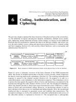
The GSM reference con®guration comprises the functional blocks of a mobile station
(Figure 9.1) at the user±network interface Um. The mobile equipment is subdivided into
a Mobile Termination (MT) and various combinations of Terminal Adapter (TA) and
Terminal Equipment (TE), depending on the kind of service access and interfaces offered
to the subscriber.
At the interface to the mobile network, the air interface Um, MT units are de®ned. An
integrated mobile speech or data terminal is represented only by an MT0. The MT1 unit
goes one step further and offers an interface for standard-conforming equipment at the
ISDN S reference point, which can be connected directly as end equipment. Likewise,
normal data terminal equipment with a standard interface (e.g. V.24) can be connected via
a TA and this way use the mobile transmission services. Finally, the TA functionality has
been integrated into units of type MT2.
At the S or R reference point, the GSM bearer or data services are available (access points
1 and 2 in Figure 9.1), whereas the teleservices are offered at the user interfaces of the TE
(access point 3, Figure 9.1). Among the bearer services besides the transmission of digi-
tized speech, there are circuit-switched and packet-switched data transmission. Typical
teleservices besides telephony are, for example, Short Message Service (SMS), Group 3
fax service, or emergency calls from anywhere.
9.2 Overview of Data Communication
Voice service needs only a switched-through physical connection, which changes its bit
rate in the BSS due to the speech transcoding in the TRAU. From the MSC on, the speech
9
GSM Switching, Services and Protocols: Second Edition. Jo
È
rg Eberspa
È
cher,
Hans-Jo
È
rg Vo
È
gel and Christian Bettstetter
Copyright q 2001 John Wiley & Sons Ltd
Print ISBN 0-471-49903-X Online ISBN 0-470-84174-5
signals in GSM networks are transported in standard ISDN format with a bit rate of
64 kbit/s. In comparison, realizing data services and the other teleservices like Group 3
fax is considerably more complicated. Because of the psychoacoustic compression proce-
dures of the GSM speech codec, data cannot be simply transmitted as a voiceband signal as
in the analog network ± a complete reconstruction of the data signal would not be possible.
Therefore, a solution to digitize the voiceband signal similar to ISDN is not possible.
Rather the available digital data must be transmitted in unchanged digital form by avoiding
speech codecs in the PLMN, as is possible in the ISDN. Here we have to distinguish two
areas where special measures have to be taken: ®rst, the realization of data and teleservices
at the air interface or within the mobile network, and second, at the transition between
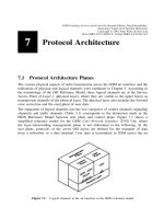
mobile and ®xed network with the associated mapping of service features. These two areas
are illustrated schematically in Figure 9.2.
A PLMN offers transparent and nontransparent services. These bearer services carry data
between the MT of the mobile station and the Interworking Function (IWF) of the MSC.
For the realization of bearer services, the individual units of the GSM network de®ne
several functions:
9 Data Communication and Networking
210
Figure 9.1: GSM reference con®guration
² Bit Rate Adaptation (RA)
² Forward Error Correction (FEC)
² ARQ error correction with the Radio Link Protocol (RLP)
² Adaptation protocol Layer 2 Relay (L2R)
For the transmission of transparent and nontransparent data, several rate adaptation stages
are required to adapt the bit rates of the bearer services to the channel data rates of the radio
interface (traf®c channels with 3.6 kbit/s, 6 kbit/s, and 12 kbit/s) and to the transmission
rate of the ®xed connections. A bearer service for data transmission can be realized in the
following two ways: 9.6 kbit/s data service requires a full-rate traf®c channel, all other data
services can either be realized on a full-rate or half-rate channel. A mobile station must
support both types of data traf®c channels, independent of what is used for speech trans-
mission. The data signals are transcoded ®rst from the user data rate (9.6 kbit/s, 4.8 kbit/s,
2.4 kbit/s, etc.) to the channel data rate of the traf®c channel, then further to the data rate of
the ®xed connection between BSS and MSC (64 kbit/s) and ®nally back to the user data
rate. This bit rate adaptation (RA) in GSM corresponds in essence to the bit rate adaptation
in the ITU-T standard V.110, which speci®es the support of data terminals with an inter-
face according to the V. series on an ISDN network [34].
On the radio channel, data is protected through the forward error correction procedures
(FEC) of the GSM PLMN; and for nontransparent data services, data is additionally
protected by the ARQ procedure of RLP on the whole network path between MT and
MSC. Thus RLP is terminated in the MT and MSC. The protocol adaptation to RLP of
Layers 1 and 2 at the user interface is done by the Layer 2 Relay (L2R) protocol.
Finally, the data is passed on from MSC or GMSC over an Interworking Function (IWF) to
the respective data connection. The bearer services of the PLMN are transformed to the
bearer services of the ISDN or another PLMN in the IWF, which is usually activated in an
MSC near the MS, but could also reside in the GMSC of the network transition. In the case
of ISDN this transition is relatively simple, since it may just require a potential bit rate
adaptation. In the case of an analog PSTN, the available digital data must be transformed
by a modem into a voiceband signal, which can then be transmitted on an analog voiceband
of 3.1 kHz.
The bearer services realized in this way can offer the protocols that may be required for the
support of teleservices between TE and IWF. An example is the fax adaptation protocol.
9.2 Overview of Data Communication
211
Figure 9.2: Bearer services, interworking, and teleservices
The fax adapter is a special TE which maps the Group 3 fax protocols with their analog
physical interface upon the digital bearer services of a GSM PLMN. Thus, after another
adaptation into an analog fax signal in the IWF of the MSC, it enables the end-to-end
transfer of fax messages according to the ITU-T Standard T.30.
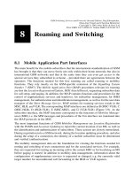
A possible interworking scenario for transparent data services of GSM with transition to a
PSTN is shown in Figure 9.3. The analog circuit-switched connection of the PSTN repre-
sents a transparent channel which can be used to transport arbitrary digital data signals in
the voiceband. In the analog network, a subscriber selects telephone or modem depending
on whether he or she wants to transmit speech or data. In the PLMN, however, the channel
coding has to be changed for different services (error protection for different bearer
services, see Section 6.2). The bit rate adaptation has to be activated and the speech coding
deactivated. In the IWF of the MSC, besides the bit rate adaptation, a modem needs to be
added for data communication with the partner in the ®xed network. In the GSM network,
voice signals therefore take a different path than data signals; in the case shown in Figure
9.3, the data signals are directed from the IWF to the modem, where they are digitized,
then passed on after bit rate adaptation to transmission on the radio channel. In the opposite
direction, the IWF passes the PCM-coded information on an ISDN channel (64 kbit/s) to
the GMSC. From there it is transformed into an analog signal in a network transition
switching unit and carried as a voiceband signal in the PSTN to the analog terminal.
After these introductory remarks, the GSM data and teleservices and their realization are
discussed in more detail in the following sections.
9.3 Service Selection at Transitions between Networks
A speci®c interworking problem arises for data services between PLMN and ISDN/PSTN
networks. Mobile-terminated calls require that the calling subscriber (ISDN or PSTN
subscriber) tells the GMSC which service (speech, data, fax, etc.) he or she wants to
use. In ISDN, a Bearer Capability (BC) information element would have to be included
in the setup message. This BC information element could then be passed on by the
9 Data Communication and Networking
212
Figure 9.3: Interworking scenario PLMN-PSTN for transparent data services
network transition switching unit to the GMSC and from there to the local MSC, which
could thus activate the required resources. In the course of call processing (CC, see Section
7.4.5), the mobile station would also be informed about the kind of service requested by the
calling subscriber and could activate the needed functions. The calling subscriber,
however, if there is no ISDN signaling as in analog networks, is not able to do this kind
of BC signaling. The service selection therefore has to use another mechanism. The GSM
standard proposes two possible solutions, which are always to be used for service selection
independent of the type of originating network (ISDN or PSTN).
² Multinumbering: the home network with this option assigns to each mobile subscriber
several MSISDN numbers, each with a speci®c Bearer Capability (BC), which can be
obtained at each call from the HLR. This way the service that an incoming call wants is
always uniquely determined. The BC information element is given to the mobile station
when the call is being set up, so the MS can decide based on its technical features
whether it wants to accept the call.
² Single numbering: only a single MSISDN is assigned to the mobile subscriber, and there
is no BC information element transmitted with an incoming call. The MS recognizes
then that a speci®c BC is needed when a call is accepted and requests the BC from the
MSC. If the network is able to offer the requested service, the call is switched through.
Usually, the multinumbering solution is favored, since one can already verify at call arrival
time in the MSC whether the requested resources are available, and the MSC side can
decide about accepting the call. There is no negotiation about the BC between MS and
MSC, so no radio resources are occupied unnecessarily, and the call set-up phase is not
extended.
9.4 Bit Rate Adaptation
Five basic traf®c channels are available in GSM for the realization of bearer services:
TCH/H2.4, TCH/H4.8, TCH/F2.4, TCH/F4.8, TCH/F9.6 (see Tables 5.2 and 6.2) with bit
rates of 3.6 kbit/s, 6 kbit/s, and 12 kbit/s. In recent standardization efforts, a TCH/F14.4
has also been de®ned. The bearer services (Table 4.2) with bit rates from 300 bit/s up to
9.6 kbit/s must be realized on these traf®c channels. Furthermore, on the ®xed connections
of the GSM network, the data signals are transmitted with a data rate of 64 kbit/s.
The terminals connected at reference point R have the conventional asynchronous and
synchronous interfaces. The data services at these interfaces work at bit rates as realized by
GSM bearer services. Therefore, the data terminals at the R reference point have to be bit
rate adapted to the radio interface. This bit rate adaptation is derived from the V.110
standard used in ISDN in which the bit rates of the synchronous data streams are going
through a two-step procedure; ®rst, frames are formed at an intermediate rate which is a
multiple of 8 kbit/s; this stream is converted to the channel bit rate of 64 kbit/s [7]. The
asynchronous services are preprocessed by a stuf®ng procedure using stop bits to form a
synchronous data stream.
A V.110 procedure modi®ed according to the requirements of the air interface is also used
in GSM. In essence, GSM performs a transformation of the data signals from the user data
rate (e.g. 2.4 kbit/s or 9.6 kbit/s) at the R reference point to the intermediate data rate
9.4 Bit Rate Adaptation
213
(8 kbit/s or 16 kbit/s) and ®nally to the ISDN bit rate of 64 kbit/s. The adaptation function
from user to intermediate rate is called RA1; the adaptation function from intermediate rate
to ISDN is called RA2. A GSM-speci®c bit rate adaptation step is added between the
intermediate rate and the channel data rate (3.6 kbit/s, 6 kbit/s, or 12 kbit/s) of the traf®c
channel at the reference point Um of the air interface. This adaptation function from
intermediate to channel bit rate is designated as RA1/RA1
0
. An adaptation function
RA1
0
performs the direct adaptation from user to channel data rate without going through
the intermediate data rate. Table 9.1 gives an overview of the bit rates at the reference
points and the intermediate data rates between the RA modules.
Adaptation frames are de®ned for the individual bit rate adaptation steps. These frames
contain signaling and synchronization data besides the user data. They are de®ned based
on V.110 frames, and one distinguishes three types of GSM adaptation frames according to
their length (36 bits, 60 bits, and 80 bits) as shown in Figures 9.4 and 9.5.
The conversion of data signals from user to intermediate rate in the RA1 stage uses the
regular 80-bit frame of the V.110 standard. In this adaptation step, groups of 48 user data
bits are supplemented with 17 ®ll bits and 15 signaling bits to form an 80-bit V.100 frame.
Because of the ratio 0.6 of user data to total frame length, this adaptation step converts user
data rates of 4.8 kbit/s into 8 kbit/s and from 9.6 kbit/s to 16 kbit/s. All user data frames of
less then 4.8 kbit/s are ``in¯ated'' to a data signal of 4.8 kbit/s by repeating the individual
data bits; for example, a 2.4 kbit/s signal all bits are doubled, or with a 600 bit/s signal the
bits are written eight times into an RA1 frame.
At the conversion of the intermediate data rate to the channel data rate in the RA1/RA1
stage, the 17 ®ll bits and 3 of the signaling bits are removed from the RA1 frame, since they
are only used for synchronization and not needed for transmission across the air interface.
This yields a modi®ed V.100 frame of length 60 bits (Figure 9.5), and the data rate is
adapted from 16 kbit/s to 12 kbit/s or from 8 kbit/s to 6 kbit/s, respectively.
9 Data Communication and Networking
214
Table 9.1: Data rates for GSM bit rate adaptation
Interface Data rate (kbit/s) Interface (kbit/s)
User Intermediate Radio S
Reference point R ± Um S
RA1 #2.4 8
RA1 4.8 8
RA1 9.6 16
RA2 8 64
RA2 16 64
RA1/RA1
0
8 3.6
RA1/RA1
0
86
RA1/RA1
0
16 12
In the case of user data rates of 4.8 kbit/s or 9.6 kbit/s, adaptation to the channel data rate
is already complete. Only for user data rates of less than 4.8 kbit/s do additional parts of
the multiple user bits need to be removed, which results in a modi®ed V.110 frame of
36 bits. Thus the user data rates of less than 4.8 kbit/s are adapted to a channel data rate of
3.6 kbit/s. The user data bits of a 2.4 kbit/s signal are then not transmitted twice anymore,
or the 600 bit/s user data signals are only written four times into the frames of the RA1
0
stage. This is, however, only true for the transparent bearer services. For the nontranspar-
ent bearer services, the modi®ed 60-bit V.110 frame is used completely for the transmis-
sion of the 60 data bits of an RLP PDU. The required signaling bits are multiplexed with
user data into the RLP frame through the Layer 2 Relay protocol L2R.
The modem used for communication over the PSTN resides in the IWF of the MSC, since
data is transmitted from here on in digital form within the PLMN. For congestion and ¯ow
9.4 Bit Rate Adaptation
215
Figure 9.4: V.110 80-bit adaptation frame for the RA1 stage
Figure 9.5: Modi®ed V.110 adaptation frame for the RA1
0
stage
control and other functions at the modem interface, the interface signals must therefore be
carried from the modem through the PLMN to the mobile station. For this purpose,
signaling bits are reserved in the frames of the bit rate adaptation function, which represent
these signals and thus give the MS direct modem control. The connection of such a bearer
service is therefore transparent not only for user data, but also for out-of-band signaling of
the (serial) modem interface in the IWF.
9.5 Asynchronous Data Services
Asynchronous data transmission based on the V. and X. series interfaces is widespread in
®xed networks. In order to support such ``non-GSM'' interfaces, the mobile station can
include a Terminal Adapter (TA) over which standard terminals with a V. or X. interface
(e.g. V.24) can be connected. Such an adaptation unit can also be integrated into the mobile
station (MT2, Figure 9.1).
Flow control between TA and IWF can be supported in different ways, just as in ISDN:
² No Flow Control: It is handled end-to-end in higher protocol layers (e.g. transport layer)
² Inband Flow Control with X-ON/X-OFF protocol
² Out-of-Band Flow Control according to V.110 through interface leads 105 and 106.
9.5.1 Transparent Transmission in the Mobile Network
In the case of transparent transmission, data is transmitted with pure Layer 1 functionality.
Besides error protection at the air interface, only bit rate adaptations are performed.
User data is adapted to the traf®c channel at the air interface according to the data rate and
protected with forward error-correcting codes (FECs) against transmission errors. As an
example, Figure 9.6 shows the protocol model for transparent asynchronous data transmis-
sion over an MT1 with an S interface. Data is ®rst converted in the TE1 or TA into a
synchronous data stream by bit rate adaptation (stage RA0). In further stages, data rates are
adapted with an MT1 to the standard ISDN (RA1, RA2), and then converted in MT1 over
RA2, RA1, and RA1
0
to the channel bit rate at the air interface. Provided with an FEC, the
data is transmitted and then converted again in the BSS by the inverse operations of bit rate
adaptation to 64 kbit/s at the MSC interface. But much more frequently than an MT1 with
an (internal) S interface, mobile stations realize a pure R interface without internal conver-
sion to the full ISDN rate in the RA2 stage. This avoids the bit rate adaptation step RA2
and thus the conversion to the intermediate data rate in the RA1 stage. The signal is
converted immediately after the asynchronous±synchronous conversion in the RA0
stage from the user data rate to the channel data rate (stage RA1
0
).
A variation without terminal adapter is shown schematically in Figure 9.7. Here the
complete interface functionality, Interface Circuit (I/Fcct), for a serial V. interface is
integrated with the required adaptation units. The data signals D are converted into a
synchronous signal in MT2 (RA0), packed into a modi®ed V.100 frame together with
signaling information S from the V interface, and adapted to the channel data rate
(RA1
0
). After FEC, the data signals are transmitted over the air interface and ®nally
9 Data Communication and Networking
216
converted for further transmission to the data rate of an ISDN B channel after decoding
and potential error correction in the BSS (RA2).
Figure 9.8 shows a complete scenario with all appropriate network transitions for a trans-
parent bearer service with modem in the interworking function for the conversion of the
digital data signals into an analog voiceband signal. A mobile data terminal uses the
transparent bearer service of a GSM PLMN over an R interface (S interface is also
9.5 Asynchronous Data Services
217
Figure 9.6: Transparent transmission of asynchronous data in GSM
Figure 9.7: Transparent transmission of asynchronous data across the R interface
possible). The data is circuit-switched to the IWF in the MSC. To communicate with a
modem in the ®xed network, the IWF activates an appropriate modem function and
converts the digital data signals into an analog voiceband signal. The IWF digitizes this
voiceband signal again and passes the data on in PCM-coded format through the GMSC.
After the network transition, the data signal is ®nally transmitted to the modem of the
communication partner. This modem can be within a terminal in the PSTN or belong to an
ISDN terminal. Before being transmitted in the PSTN, the PCM-coded signal is again
converted into an analog voiceband signal. In ISDN the signal is transmitted as a PCM-
coded signal of category 3.1 kHz audio; a repeated conversion is not necessary. An ISDN
subscriber needs an adaptation unit TA
0
for the conversion of the digital voiceband signal
into an analog signal, which can then be processed further with a modem and passed on to
the data terminal.
Another variant consists of a circuit-switched modem connection to a packet-switched
network access node, as is possible from ®xed connection ports. In these access nodes, the
asynchronous modem signals are combined into packets in a Packet-Assembler/Disassem-
bler (PAD) module and then transmitted through the packet-switched network. This
variant of packet network access has the disadvantage that one has to switch through to
the PAD over a long path, especially in the case of international roaming, since usually the
nearest PAD is not the one allowed to the subscriber for access to packet networks.
It is also possible to connect to standard ISDN terminals without an analog modem based
on the digital data transmission capability of ISDN. For this purpose, the transmission
mode Unrestricted Digital has been de®ned. In this case, there is only a bit rate adaptation
according to V.110 (Figure 9.9). The data arrives at the MSC from the BSS in V.110
frames on an ISDN channel with 64 kbit/s and transparently is passed on to the ISDN using
a B channel again in V.110 frames. The otherwise necessary modems are entirely un-
9 Data Communication and Networking
218
Figure 9.8: Principle of transparent asynchronous data transfer (variant with modem)
necessary in the case of Unrestricted Digital connections. However, an ISDN subscriber
can connect a terminal through an analog modem by using an adaptation unit TA
0
which
converts the unrestricted digital signal into a voiceband signal according to one of the V.
standards.
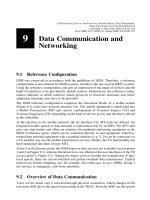
The quality of transparent data services in GSM varies with the radio ®eld conditions. This
is illustrated by examples of comparative ®eld measurements of the transparent data
service BS26 with 9.6 kbit/s data rate, comparing a moving and a standing mobile station.
Figure 9.10 shows the weighted distribution of the bit errors of these two cases for a block
length of 1024 bits. The weighted distribution indicates the frequency with which m bit
errors occur in a block of length n bits (here n 1024):
Pm; n
X
1
im
Pi errors in n-bit-block
The distribution shown in Figure 9.10 represents measurements of the error statistics of
BS26 which were performed in 1994 in a suburban area for moving and standing mobile
stations [58]. Notice that the error frequency for the standing mobile station (``stationaer'')
is clearly lower than for the moving mobile station (``mobil''). This result is obtained by
averaging measurements over several locations and measurement tours. The resulting
mean shows, for the moving station, a sometimes heavily varying channel due to the
unavoidable fading phenomena, which frequently cause bursts with high bit error ratios,
again resulting in an aggregate higher mean bit error ratio and thus also a higher packet
error ratio P(1, 1024).
9.5.2 Nontransparent Data Transmission
In contrast to the transparent transmission mode, the nontransparent mode in GSM data
9.5 Asynchronous Data Services
219
Figure 9.9: Transparent data transfer to an ISDN (unrestricted digital)
services protects the user data within the PLMN through a Layer 2 protocol, the Radio Link
Protocol (RLP), in addition to the FEC procedures (convolutional coding, interleaving).
This protection protocol further reduces the residual bit error ratio of data transmission in
the mobile network. However, the automatic repeat requests (ARQ) of the RLP introduces
additional transmission delays on the data path, and the effective user data throughput is
reduced (protocol overhead).
User data between MT and MSC/IWF is protected on Layer 2 by the RLP. Two kinds of
transmission errors are corrected this way: ®rst, those caused by radio interference and
remaining uncorrected by FEC, and second, those caused through the interruptions of
handover. For signaling on the FACCH, time slots are ``stolen'' from the data traf®c
channel, which can cause data losses. The RLP protects user data against such losses, too.
For nontransparent data transfer with RLP, an additional sublayer in Layer 2 is required,
the Layer 2 Relay (L2R) protocol. This relay protocol maps user data and status informa-
tion of the IWF user±modem interface onto the information frames of the RLP. Depending
on the kind of user data (character- or bit-oriented), one of two variations of the L2R is
used: Layer 2 Relay Bit Oriented Protocol (L2RBOP), or Layer 2 Relay Character
Oriented Protocol (L2RCOP). An L2R PDU is handed to RLP as a service data unit
(SDU) and inserted into the RLP frame as a data ®eld. The ®rst octet of an L2R PDU
always contains control information, like the status of the signaling lines of the serial
interface. Beyond that, the L2R PDU can contain an arbitrary number of such status octets.
They are always inserted into the user data stream when the state of the interface changes
(e.g. hardware ¯ow control). Thus, of the 200 user data bits (Figure 7.10), only a maximum
of 192 can be used for payload. However, since the signaling information is already
contained in the L2R PDU, these bits must not be considered for bit rate adaptation.
Thus the modi®ed 60-bit V.110 frame (Figure 9.5) can be completely occupied with
data bits, and the full channel rate of maximum 12 kbit/s can be used for the transmission
9 Data Communication and Networking
220
Figure 9.10: Weighted distribution of a transparent GSM bearer service (BS26)
of RLP data. Next come a set of four modi®ed V.110 frames which carry a complete RLP
frame. Considering the protocol overhead of RLP (16.7%) and the minimum overhead of
an L2R PDU (0.5%), one obtains a usable subscriber data rate of up to 9.95 kbit/s.
The protocol model for asynchronous nontransparent character-oriented data transmission
over the S interface in GSM is now presented as an example (Figure 9.11). Data is
transmitted by L2R protocol and L2R Character Oriented Protocol (L2RCOP) and RLP
from the MT1 termination to the MSC. In between, as in the transparent case, are FEC,
RA1, RA1
0
, and RA2. The RLP frames are transported in a synchronous mode. Only the
user data stream at the user interface is asynchronous, and in the case of the model in
Figure 9.11 the user data stream must be converted for the S interface into a synchronous
data stream (RA0). In the case of a terminal with V. interface and an MT2 termination
(reference point R), this bit rate adaptation at the S interface would be avoided. The
asynchronous data is then directly accepted at the serial interface by the L2R (I/Fcct);
potential start/stop bits are removed, and data are combined into L2R PDUs.
9.5 Asynchronous Data Services
221
Figure 9.11: Nontransparent data transmission in GSM
A complete scenario for network transition with nontransparent asynchronous GSM data
services is shown in Figure 9.12. The RLP is terminated in the MSC/IWF, and user data are
converted again into an asynchronous data stream by the associated L2R. For the nontran-
sparent case too, the IWF offers both variants for the network transition: ®rst, using
modems and, second, Unrestricted Digital. In the case of a network transition to the
PSTN or to a 3.1 kHz audio connection into ISDN, the respective modem function is
inserted and passes PCM-coded data to the GMSC (not shown in Figure 9.12), which
directs them into the ®xed networks. Using several bit rate adaptation steps (RA0 ± RA1 ±
RA2, Figure 9.12), the user data can also be converted in the IWF into a synchronous
Unrestricted Digital signal, which is then carried transparently over an ISDN B channel
with 64 kbit/s.
9.5.3 PAD Access to Public Packet-Switched Data Networks
9.5.3.1 Asynchronous Connection to PSPDN PADs
As shown in Figures 9.8 and 9.12, access to Packet Switched Public Data Networks
(PSPDNs), e.g. Accunet in the USA or Datex-P in Germany, is already possible using
the asynchronous services of GSM. This requires a Packet Assembler/Disassembler
(PAD) in the PSPDN, which packages the asynchronous data on the modem path into
X.25 packets and also performs the reverse operation of unpacking. PAD access uses the
protocols X.3, X.28, and X.29 (Triple X Pro®le). Just as from the ®xed network, the mobile
subscriber dials the extension of a PAD for access to the service of the PSPDN, provided
packet network access is allowed. In this way, the subscriber has the same kind of access to
the packet network as a subscriber from the ®xed network, aside from the longer transmis-
9 Data Communication and Networking
222
Figure 9.12: Principle of nontransparent data transfer
sion delays and the higher bit error ratios. It is therefore recommended to transmit data for
PAD access across the air interface in the PLMN in nontransparent mode with RLP [21].
9.5.3.2 Dedicated PAD Access in GSM
However, direct access to packet data networks through the asynchronous GSM data
services has disadvantages:
² One needs another subscription to a packet data network operator besides to GSM.
² Independent of the current mobile subscriber's location, a circuit-switched connection
to a PAD of a packet service provider is needed. Sometimes the packet network access
is only allowed to speci®c PADs. This is a particular disadvantage if the mobile
subscriber is currently in a foreign GSM network and incurs fees for international lines.
Therefore, GSM has de®ned another PSPDN access without these disadvantages: Dedi-
cated PAD Access (Figure 9.13). The services are de®ned as Bearer Services BS41 through
BS46 (Table 4.2). With this kind of PSPDN access from a PLMN, each PLMN has at least
one PAD that is responsible for the packaging/unpackaging of the X.25 packets of the
respective mobile subscriber.
For this purpose, a PAD is activated as an additional resource in the IWF or in an especially
reserved MSC (Figure 9.13). This PAD can be reached in asynchronous mode again over
transparent or nontransparent PLMN connections. However, with this solution the connec-
tion to the PAD is as short as possible, since a PAD is already reached in the nearest IWF,
and international lines are never occupied for PAD access. Packetization of user data is
already performed within the mobile network rather than in the remote PAD of a packet
network operator, hence there is no need for a separate subscriber agreement with this
9.5 Asynchronous Data Services
223
Figure 9.13: Dedicated PAD access through asynchronous GSM data services
packet network operator. The dedicated PAD of the current PLMN is now responsible for
the packaging/unpackaging of the asynchronous data into/from X.25 packets, which are
then passed on through a speci®c interworking MSC (P-IWMSC) to a public PSPDN (e.g.
Transpac in France or Sprint's Telenet in the USA) [21].
The dedicated PAD has a uniform pro®le in all GSM networks; it is reached in each
network with the same access procedure. Even in foreign PLMNs, a mobile station there-
fore gets the earliest and lowest cost access to the packet data network. Charging occurs to
the account of the GSM extension (MSISDN) of the mobile subscriber; a separate Network
User Identi®cation (NUI) for the PSPDN is not necessary. However, only outgoing packet
connections are possible.
9.6 Synchronous Data Services
9.6.1 Overview
Synchronous data services allow access to synchronous modems in the PSTN or ISDN as
well as to circuit-switched data networks. Such access is not very signi®cant; however,
synchronous data services are de®ned in GSM. The essential differences to the asynchro-
nous data transmission procedures are in bit rate adaptation and modems. For a synchro-
nous data service, no RA0 bit rate adaptation is needed (conversion from asynchronous to
synchronous), since data is already in synchronous format. Instead, special synchronous
modems are required in the IWF. Synchronous data services can only be offered in
transparent mode, with the exception of access to X.25 packet networks, which are a
signi®cant application of synchronous data service in GSM.
9.6.2 Synchronous X.25 Packet Data Network Access
The protocol model shown in Figure 9.14 is the model for synchronous data transmission
in nontransparent mode with the packet data access protocol according to the ITU-T
standard X.25. Because of the nontransparent transmission procedure, the X.25 Link
Access Procedure B (LAPB) must be terminated in the MT as well as in the IWF. Since
LAPB of the X.25 protocol stack operates in a bit-oriented mode, the Layer 2 Relay Bit
Oriented Protocol (L2RBOP) is required.
9.6.2.1 Basic Packet Mode
Two variants of PSPDN access can be realized with the protocol model in Figure 9.14:
² PSPDN access according to ITU-T X.32
² Access to PSPDN packet handlers according to ITU-T X.31 Case A (basic packet
mode).
PSPDN access according to X.32 has not met much acceptance with the applications; the
X.31 procedure is used more often.
PSPDN access according to X.32 is the simpler variant. The X.25 packets can be trans-
9 Data Communication and Networking
224
ferred directly over a synchronous modem in the IWF to the PSPDN. This does not
necessarily require nontransparent transmission in GSM, but it helps because of the
lower bit error ratio. In case of the nontransparent transmission, the LAPB protocol has
to be terminated in MT and IWF (see above). The subscriber needs a Network User
Identi®cation (NUI). Incoming and outgoing packet connections are possible, but again
there is the problem of needing circuit-switched connections to the home PLMN, just like
in case of international roaming.
The access procedure according to ITU-T standard X.31 Case A (basic packet mode) is the
more favored variant of this group of services. The X.25 packets of the mobile subscriber
are passed from the IWF to the packet handler of the ISDN. Since speed adaptation with
the X.31 procedure is performed in the ISDN B channel by ¯ag stuf®ng, the protocol has to
be terminated in the IWF, which means that the nontransparent mode of GSM can be used.
In this case too, there are connections possible only through the packet handler of the home
network.
9.6.2.2 Dedicated Packet Mode
As in the case of asynchronous PAD access to packet data networks (see Section 9.5.3), the
synchronous case of the X.25 access protocol also offers an alternative, which allows the
most immediate transition to the PSPDN, even if the mobile station is in a foreign network
(international roaming). For this purpose, a dedicated mode is also de®ned with each
PLMN having its own packet handler.
Figure 9.15 shows the principle of this Dedicated Packet Mode. It essentially includes the
functions of the basic packet mode, with the difference that the packet handler is integrated
9.6 Synchronous Data Services
225
Figure 9.14: X.25 access at the ISDN S interface
into the GSM network. Data is transmitted in the PLMN in nontransparent and synchro-
nous mode. Access to the packet handler is the same in all PLMNs, and is also available to
foreign mobile subscribers. Since packet data networks do not know roaming, only
outgoing data calls are possible.
9.7 Teleservices: Fax
In the following, we brie¯y explain the realization of the GSM fax service.
The GSM standard considers the connection of a regular Group 3 fax terminal with its
two-wire interface to an appropriately equipped mobile station as the standard con®g-
uration of a mobile fax application. The GSM fax service is supposed to enable this
con®guration to conduct fax transmissions with standard Group 3 fax terminals over
mobile connections. This requires mapping the fax protocol of the analog two-wire
interface onto the digital GSM transmission, because the fax procedure de®nes a
complete protocol stack with its own modulation, coding, user data compression, inband
signaling, etc. Therefore the Fax Adapter (FA) has been de®ned for this mapping. The
principle is summarized in Figure 9.16. The fax adapter of the mobile station converts the
fax protocol of a standard Group 3 fax terminal on an analog two-wire line into a GSM
internal fax adapter protocol. The PDUs of the adapter protocol are transmitted over the
MT with the GSM data services to the fax adapter in the IWF of the MSC, and there they
are again converted into the T.30 protocol on the analog line, or transmitted to the ISDN
in PCM-coded format, where again a terminal adapter allows connection of a Group 3
fax terminal (not shown in Figure 9.16).
A more compact version of a mobile fax terminal is possible, if the fax adapter and the
Group 3 fax terminal are integrated into a compact terminal (GSM fax, Figure 9.16). Such
equipment can be connected at reference point R to an MT2. It delivers a digital signal
directly. With this integration, the analog two-wire line interface becomes super¯uous.
9 Data Communication and Networking
226
Figure 9.15: Dedicated packet mode with packet handler in GSM
Hence all the analog functions can be omitted such as demodulation and digitalization of
the Group 3 fax signals, i.e. the GSM fax needs no analog components such as a modem
building block. Therefore, however, the integrated GSM fax must implement the fax
adapter protocol and terminate it at reference point R in order to guarantee correct control
of the analog fax components in the fax adapter of the IWF.
A complete fax scenario with the required analog components in the fax adapter is illu-
strated in Figure 9.17. The FA needs several function blocks in the MS as well as in the
IWF for the conversion of the fax protocol of the analog a/b interface to the digital
transmission procedure in the PLMN. Group 3 fax equipment according to ITU-T standard
9.7 Teleservices: Fax
227
Figure 9.16: Fax adapter in GSM
Figure 9.17: Overview of GSM procedure for fax service
T.30 employs three modem building blocks, all three operating in half-duplex mode. A
V.21 modem (300 bit/s) is used for the signaling phase to set up a fax connection, whereas
the information transfer phase uses a V.27ter modem (4.8 kbit/s or 2.4 kbit/s) or a V.29
modem (9.6 kbit/s, 4.8 kbit/s, and 2.4 kbit/s). For conversion from analog signaling tones
into messages of the fax adapter protocol, the fax adapter needs an additional Tone
Handler. It is used to transfer the (re-)digitized fax signals over either a transparent or a
nontransparent GSM bearer service to the IWF in the MSC. The fax adapter protocol
provides a complete mapping of the T.30 protocol, such that the IWF is able to handle
the complete fax protocol with the partner entity. From the view of the partner entity, the
complete GSM connection consisting of fax adapter, mobile station, and IWF represents a
physical connection with a mobile Group 3 fax terminal.
Fax service poses special demands on the service quality of the data channel which the
GSM network provides for this teleservice. In particular, propagation delays must remain
below a maximum threshold, since timers of the T.30 protocol expire otherwise. This is
especially critical if RLP is used to reduce transmission errors, which introduces additional
delays into the data path through its ARQ procedure.
Two fax services are speci®ed: the transparent procedure and the nontransparent proce-
dure, depending on the kind of bearer service used. The resulting protocol models are
shown in Figures 9.18 and 9.19, respectively. It is evident that in both cases the fax
protocol is superimposed onto the respective bearer service. The transparent fax procedure
9 Data Communication and Networking
228
Figure 9.18: Transparent fax procedure in GSM Radio Interface BSS-MSC
Figure 9.19: Nontransparent fax procedure in GSM
is easier to realize, although with its transparent bearer service, it incurs a correspondingly
variable fax quality.
In contrast, the nontransparent fax procedure based on RLP is very well protected against
transmission errors, and it delivers very acceptable quality of the transmitted documents
over a wide range of distances. However, due to the varying transmission conditions, there
are also variable delays of the RLP which lead to intermediate buffering of fax signals in
the FA and which, in the worst case, can cause the breakdown of the fax transfer [16].
9.7 Teleservices: Fax
229