Tài liệu GSM Switching, Services and Protocols P11 pptx
Bạn đang xem bản rút gọn của tài liệu. Xem và tải ngay bản đầy đủ của tài liệu tại đây (569.19 KB, 26 trang )
GSM ± The Story Goes On
12.1 Globalisation
GSM is now in more countries than McDonalds.
Mike Short, Chairman MoU Association 1995±1996
GSM was initially designed as a pan-European mobile communication network, but
shortly after the successful start of the ®rst commercial networks in Europe, GSM systems
were also deployed on other continents (e.g. in Australia, Hong Kong, and New Zealand).
In the meantime, 373 networks in 142 countries are in operation (see Section 1.3).
In addition to GSM networks that operate in the 900 MHz frequency band, so-called
Personal Communication Networks (PCN) and Personal Communication Systems (PCS)
are in operation. They are using new frequencies around 1800 MHz, and in North America
around 1900 MHz. Apart from the peculiarities that result from the different frequency
range, PCN/PCS networks are full GSM networks without any restrictions, in particular
with respect to services and signaling protocols. International roaming among these
networks is possible based on the standardized interface between mobile equipment and
the SIM card, which enables personalization of equipment operating in different frequency
ranges (SIM card roaming). Furthermore, a more general standardization of the SIM
concept could allow worldwide roaming across non-GSM networks.
Besides roaming based on the SIM card, the MoU has put increasing emphasis on multi-
band systems and multiband terminals during the last years (dualband, triband). Multiband
systems permit the simultaneous operation of base stations with different frequency
ranges. In connection with multiband terminals, this approach leads to a powerful concept.
Such terminals can be operated in several frequency bands, and they can adapt automa-
tically to the frequencies used in the network at hand. This enables roaming among
networks with different frequency ranges, but also automatic cell selection in multiband
networks with different frequencies becomes possible.
12
GSM Switching, Services and Protocols: Second Edition. Jo
È
rg Eberspa
È
cher,
Hans-Jo
È
rg Vo
È
gel and Christian Bettstetter
Copyright q 2001 John Wiley & Sons Ltd
Print ISBN 0-471-49903-X Online ISBN 0-470-84174-5
12.2 Overview of GSM Services in Phase 21
GSM is not a closed system that does not undergo any change. The GSM standards are
being enhanced; and in the current phase of standardization (Phase 21) several individual
topics are being discussed. Phase 1 of the GSM implementation contained basic teleser-
vices ± in the ®rst place voice communication ± and a few supplementary services, which
had to be offered by all network operators in 1991 when GSM was introduced into the
market. The standardization of Phase 2 was completed in 1995 with market introduction
following in 1996. Essentially, ETSI added more of the supplementary services, which had
been planned already when GSM was initially conceived and which were adopted from the
®xed ISDN (see Section 4.3). These new services made it necessary to rework large parts
of the GSM standards. For this reason, networks operating according to the revised stan-
dard are also called GSM Phase 2 [45]. However, all networks and terminals of Phase 2
preserve the compatibility with the old terminals and network equipment of Phase 1, i.e. all
new standard development had to be strictly backward compatible.
The topics of Phase 21 deal with many aspects ranging from radio transmission to
communication and call processing. However, there is no complete revision of the GSM
standard; rather single subject areas are treated as separate standardization units, with the
intent of allowing them to be implemented and introduced independently from each other.
12 GSM ± The Story Goes On
272
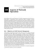
Figure 12.1: Evolution of GSM
Thus GSM systems can evolve gradually, and standardization can meet market needs in a
¯exible way. However, with this approach, a unique identi®cation of a GSM standard
version becomes impossible. The designation GSM Phase 21 is supposed to indicate this
openness [45], suggesting an evolutionary process with no endpoint in time or prescribed
target dates for the introduction of new services. The GSM standards are now published in
so-called releases (e.g. Release 97, 98, 99, and 2000).
A large menu of technical questions is being addressed, only a few of which are presented
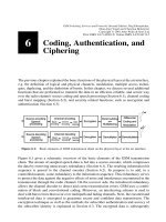
as examples in the following. Figure 12.1 illustrates the evolution of GSM, from the initial
digital speech services toward the 3rd generation of mobile communications (UMTS/IMT-
2000). In particular, it shows the services of Phase 21 that are covered in this book. Most
of these services are already offered by GSM network providers today and can be used with
enhanced mobile equipment. Some other services are in the planning stage at the time of
this writing.
12.3 Bearer and Teleservices of GSM Phase 21
Whereas GSM Phase 2 de®ned essentially a set of new supplementary services, Phase 21
is also addressing new bearer and teleservices. In this section we give an overview of these
new speech and data services. They signi®cantly improve the GSM speech quality and
make the utilization of available radio resources much more ef®cient. Furthermore, the new
data services are an important step toward wireless Internet access via cellular networks.
12.3.1 Improved Codecs for Speech Services: Half-Rate Codec, EFR
Codec, and AMR Codec
One of the most important services in GSM is (of course) voice service. Thus it is obvious,
that voice service has to be further improved. In ®rst place is the development of new
speech codecs with two competing objectives:
² better utilization of the frequency bands assigned to GSM and
² improvement of speech quality in the direction of the quality offered by ISDN networks,
which is primarily requested by professional users.
Half-Rate codec ± The reason for improved bandwidth utilization is to increase the
network capacity and the spectral ef®ciency (i.e. traf®c carried per cell area and frequency
band). Early plans were already in place to introduce a half-rate speech codec. Under good
channel conditions, this codec achieves, in spite of the half bit rate, almost the same speech
quality as the full-rate codec used so far. However, quality loss occurs in particular for
mobile-to-mobile communication, since in this case (due to the ISDN architecture) one has
to go twice through the GSM speech coding/decoding process. These multiple, or tandem,
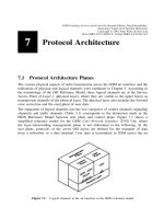
conversions degrade speech quality. The end-to-end transmission of GSM-coded speech is
intended to avoid multiple unnecessary transcoding and the resulting quality loss (Figure
12.2) [45]. This technique has been passed under the name Tandem Free Operation (TFO)
in GSM Release 98.
Enhanced Full-Rate (EFR) codec ± A very important concern is the improvement of
12.3 Bearer and Teleservices of GSM Phase 21
273
speech quality. Speech quality that is close to the one found in ®xed networks is especially
important for business applications and in cases where GSM systems are intended to
replace ®xed networks, e.g. for fast installation of telecommunication networks in areas
with insuf®cient or missing telephone infrastructure.
Work on the Enhanced Full-Rate (EFR) codec was therefore considered of high priority.
This EFR is a full-rate codec (net bit rate 12.2 kbit/s). Nevertheless, it achieves speech
quality clearly superior to the previously used full-rate codec. It has been initially stan-
dardized and used in North American DCS1900 networks [45] and has been implemented
in GSM with very good success. Instead of using the Regular Pulse Excitation±Long Term
Prediction (RPE-LTP) coding scheme (see Section 6.1), a so-called Algebraic Code Exci-
tation±Linear Prediction (ACELP) is employed.
The EFR speech coder delivers data blocks of 244 information bits to the channel encoder
(compare with Table 6.2). In addition to grading the bits into important Class I bits and less
important Class II bits, EFR further divides into Class Ia bits and Class Ib bits. A special
preliminary channel coding is employed for the most signi®cant bits: eight parity bits
(generated by a Cyclic Redundancy Check (CRC) coding) and eight repetition bits are
added to provide additional error-detection. The resulting 260 bits are processed by the
block encoder as described in Section 6.2.1.1. For convolutional coding of Class I bits the
convolutional encoder de®ned by the generator polynomials G0 and G1 is employed.
Adaptive Multi-Rate (AMR) codec ± The speech codecs mentioned before (full-rate,
half-rate, and EFR) all use a ®xed source/information bit rate, which has been optimized
for typical radio channel conditions. The problem with this approach is its in¯exibility:
whenever the channel conditions are much worse than usual, very poor speech quality will
result, since the channel capacity assigned to the mobile station is too small for error free
12 GSM ± The Story Goes On
274
Figure 12.2: Through-transport of GSM-coded speech in Phase 21
for mobile-to-mobile connections (tandem free operation)
transmission. On the other hand, radio resources will be wasted for unneeded error protec-
tion if the radio conditions are better than usual.
To overcome these problems, a much more ¯exible codec has been developed and stan-
dardized: the Adaptive Multi-Rate (AMR) codec. It can improve speech quality by adap-
tively switching between different speech coding schemes (with different levels of error
protection) according to the current channel quality. To be more precise, AMR has two
principles of adaptability [11]: channel mode adaptation and codec mode adaptation.
Channel mode adaptation dynamically selects the type of traf®c channel that a connection
should be assigned to: either a full-rate (TCH/F) or a half-rate traf®c channel (TCH/H).
The basic idea here is to adapt a user's gross bit rate in order to optimize the usage of radio
resources. If the traf®c load in a cell is high, those connections using a TCH/F (gross bit
rate 22.8 kbit/s) and having good channel quality should be switched to a TCH/H (11.4
kbit/s). On the other hand, if the load is low, the speech quality of several TCH/H connec-
tions can be improved by switching them to a TCH/F. The signaling information for this
type of adaptation is done with existing protocols on GSM signaling channels; the switch-
ing between full-rate and half-rate channels is realized by an intracell handover.
The task of codec mode adaptation is to adapt the coding rate (i.e. the trade-off between the
level of error protection versus the source bit rate) according to the current channel
conditions. When the radio channel is bad, the encoder operates at low source bit rates
at its input and uses more bits for forward error protection. When the quality of the channel
is good, less error protection is employed.
The AMR codec consists of eight different modes with source/information bit rates
ranging from 12.2 kbit/s to 4.75 kbit/s (see Table 12.1). All modes are scaled versions
of a common ACELP basis codec.
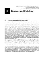
From the results of link quality measures, an adaptation unit selects the most appropriate
codec mode. Figure 12.3 illustrates the AMR encoding principle. Channel coding is
performed using a punctured recursive systematic convolutional code. Since not all bits
of the voice data are equally important for audibility, AMR also employs an Unequal Error
Protection (UEP) structure. The most important bits (Class Ia; e.g. mode bits and LPC
12.3 Bearer and Teleservices of GSM Phase 21
275
Table 12.1: AMR codec modes
Source data rate in kbit/s 12.2 10.2 7.95 7.4 6.7 5.9 5.15 4.75
Information bits per block 244 204 159 148 134 118 103 95
± Class Ia bits
(CRC-protected)
81 65 75 61 55 55 49 39
± Class Ib bits
(not CRC-protected)
163 139 84 87 79 63 54 56
Rate R of convolutional
encoder
1/2 1/3 1/3 1/3 1/4 1/4 1/5 1/5
Output bits from
convolutional encoder
508 642 513 474 576 520 565 535
Punctured bits 60 194 65 26 128 72 117 87
coef®cients) are additionally protected by a Cyclic Redundancy Check (CRC) code with 6
parity bits. On the receiver side, the decoder will discard the entire speech frame if the
parity check fails. Also the degree of puncturing depends on the importance of the bits. At
the end of the encoding process, a block with a ®xed number of gross bits results, which is
subsequently interleaved to reduce the number of burst errors.
Since the channel conditions can change rapidly, codec mode adaptation requires a fast
signaling mechanism. This is achieved by transmitting the information about the used
codec mode, link control, and DTX, etc. together with the speech data in the TCH, i.e. a
special inband signaling is employed.
We give an example: the 12.2 kbit/s codec for a TCH/F operates with 244 source bits
(12.2 kbit/s £ 20 ms), which are ®rst rearranged to subjective importance. By adding six
CRC bits for Class 1a bits, we obtain 250 bits. The subsequent recursive convolutional
encoder, de®ned by the two generators 1 and G
1
=G
0
d
4
1 d
3
1 d 1 1=d
4
1 d
3
1 d,
with rate R < 1/2, maps those bits to 508 bits. Next, 60 bits are punctured, which results in
an output sequence of 448 bits. Together with the encoded inband signaling (8 bits) this
block is interleaved and ®nally mapped to bursts. The resulting gross bit rate is thus
456 bits/20 ms 22.8 kbit/s.
12.3.2 Advanced Speech Call Items (ASCI)
GSM systems of Phase 2 offer inadequate features for group communications. For exam-
ple, group call or ``push-to-talk'' services with fast connection setup as known from private
radio or digital trunked radio systems (e.g. TETRA), are not offered. However, such
services are indispensable for most closed user groups (e.g. police, airport staff, railroad
or taxi companies). In particular railroad operators had a strong request for such features.
In 1992, their international organization, the Union Internationale des Chemins de Fer
(UIC), selected the GSM system as their standard [45]. This GSM-based uniform inter-
national railway communication system should replace a multitude of incompatible radio
systems.
In this section we describe the standardized speech teleservices that offer functionality for
group communication: the Voice Broadcast Service (VBS) and the Voice Group Call
Service (VGCS). In addition, the Enhanced Multi-Level Precedence and Pre-emption
Service (eMLPP) is used to assign and control priorities to users and their calls (e.g. for
emergency calls). All those services together are referred to as Advanced Speech Call
Items (ASCI).
12 GSM ± The Story Goes On
276
Figure 12.3: AMR channel encoding principle (bit numbers for TCH/F)
12.3.2.1 Voice Broadcast Service (VBS)
The Voice Broadcast Service (VBS) allows a user to broadcast a speech message to several
other users within a certain geographical area. The user who initiates the call can only send
(``speaker''), and all others can only listen (``listeners'').
Figure 12.4 gives a schematic illustration of a VBS scenario. Mobile users who are inter-
ested in a certain VBS group subscribe it and will then receive broadcast calls of this
group. A special permission is needed, however, for the right to send broadcast calls, i.e.
for the right to act as a speaker. The subscribed VBS groups are stored on the user's SIM
card, and if a subscriber does not want to receive VBS calls for a certain time, he or she can
deactivate them. Besides mobile GSM users, also a prede®ned group of ®xed telephone
connections can participate in the VBS service (e.g. dispatchers, supervisors, operators, or
recording machines).
12.3 Bearer and Teleservices of GSM Phase 21
277
Figure 12.4: VBS scenario (schematic illustration)
Figure 12.5: Some examples of group call areas
System Concept and Group Call Register ± The area in which a speech broadcast call is
offered is referred to as group call area. As illustrated in Figure 12.5, in general, this area
consists of several cells. A group call area may comprise cells of several MSC areas and
even of several PLMNs. One MSC is responsible for the handling of the VBS. It is called
Anchor MSC. In case a voice broadcast should also be transmitted in cells that are not
within the service area of this MSC (i.e. if the group call area contains also cells belonging
to other MSCs), the MSCs of those cells are also involved. They are then denoted as Relay
MSCs.
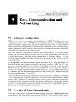
The VBS-speci®c data is stored in a Group Call Register (GCR). Figure 12.6 shows the
extended GSM system architecture. The GCR contains the broadcast call attributes for
each VBS group, which are needed for call forwarding and authentication. For example:
² Which cells belong to the group call area?
² Which MSC is the responsible anchor MSC?
² In which cells are group members currently located, i.e. in which cells is a voice
message to be broadcast?
² To which other MSCs is the voice message to be forwarded to reach all group members
who are currently located in the group call area?
² To which external ®xed telephone connections is the broadcast message addressed?
² Which ®xed telephone connections are allowed to act as speakers?
Call Establishment and Logical Channels ± A mobile station that intends to initiate a
voice broadcast call sends a service request to the BSS. The request contains the Group ID
of the VBS group to be called. Thereupon, the responsible MSC queries the user's pro®le
12 GSM ± The Story Goes On
278
Figure 12.6: Extension of the GSM system architecture with the GCR
from the VLR and checks whether the user is allowed to act as speaker for the stated group.
Afterward, some VBS-speci®c attributes are requested from the GCR. If the broadcast call
should also be transmitted in cells that do not belong to the current MSC, an anchor MSC is
determined. The anchor MSC then forwards the VBS attributes to all relay MSCs, which
then request all affected BSCs to allocate a traf®c channel in the respective cells, and to
send out noti®cation messages on the NCH (see Section 5.1). When a mobile station
receives such a message and it is also subscribing to the respective VBS group, it changes
to the given traf®c channel and listens to the voice broadcast in the downlink. The speaker
is then informed about the successful connection setup and can start talking. The noti®ca-
tion message is periodically repeated on the NCH until the speaker terminates the call.
In contrast to the paging procedure in conventional GSM calls, the individual mobile users
and their mobile stations are not explicitly addressed by an IMSI or TMSI but with the
Group ID of the VBS group. Furthermore, the mobile stations do not acknowledge the
reception of VBS calls to the network. To realize the service, traf®c channels are not
allocated to individual subscribers, but the voice signal of the speaker is broadcast to all
listening participants in a cell on one group channel. Thus, in each participating cell, only
one full-rate channel is occupied (as in regular voice calls).
12.3.2.2 Voice Group Call Service (VGCS)
Another group communication service is the Voice Group Call Service (VGCS). The
VGCS de®nes a closed user group communication service, where the right to talk can
now be passed along within the group during a call by using a push-to-talk mechanism as
in mobile radio. This principle is illustrated in Figure 12.7: User 1 initializes a group call
and speaks, while the other users listen. Afterward, User 1 releases the channel and
changes into listener mode. Now, each of the subscribers may apply for the right to become
speaker. For example, User 4 requests the channel, and the network assigns it to him/her.
He or she talks, releases the channel, and changes back to listener mode. Finally, the group
call is terminated by the initiator (in general). Whereas the information ¯ow in the VBS is
simplex, the VGCS can be regarded as a half-duplex system (compare Figures 12.4 and
12.7).
The fundamental concepts and entities of the VBS, e.g. the de®nition of group call areas,
group IDs, the GCR, and anchor and relay MSCs are also used in the VGCS.
12.3 Bearer and Teleservices of GSM Phase 21
279
Figure 12.7: Group call scenario (schematic illustration)
Logical Channels ± A traf®c channel is allocated in each cell of the group call area that is
involved in the VGCS. All group members listen to this channel in the downlink, and only
the speaker uses it in the uplink. Therefore, in addition to the tasks for VBS calls, the
network must also control uplink radio resources. The network indicates in the downlink to
all mobile stations whether the uplink channel is in use or not. If the channel is free, the
group members may send access bursts. Collisions that occur with simultaneous requests
are resolved, and the network chooses one user who obtains the channel and thus has the
right to talk.
12.3.2.3 Enhanced Multi-Level Precedence and Pre-emption (eMLPP)
Priority services enable a network to process calls with a priority class (precedence level).
If the network load is high, calls with high priority can then be treated in a preferred
manner, and resources for low priority calls can be deallocated. In the extreme case, a call
with low priority can be dropped because a call with high priority arrives (pre-emption).
The control of priorities in GSM is called Enhanced Multi-Level Precedence and Pre-
emption (eMLPP). It is a supplementary service for point-to-point speech services as well
as for VBS and VGCS. The principle of eMLPP is based on the Multi-Level Precedence
and Pre-emption (MLPP) [33] method used in SS#7. In doing so, MLPP has been
enhanced with functions for priority control at the air interface. Table 12.2 lists all priority
classes of eMLPP. Besides the ®ve precedence levels that are used in MLPP (Classes 0±4),
two additional levels with higher priority are de®ned (Classes A and B). The table also
shows whether a call with higher priority may terminate a call with lower priority. It is
important to note that only the operator may use calls of Class A and B, such that for
example an emergency call over VBS or VGCS can be initiated in disaster situations. Calls
of this class can only be employed within the service area of one MSC. The other ®ve
classes can be utilized within the entire PLMN and also in combination with the MLPP of
ISDN. The highest priority call that a subscriber is allowed to use is stored on his or her
SIM card and in the HLR.
12 GSM ± The Story Goes On
280
Table 12.2: Priority classes in eMLPP
Class Used by Connection
setup
Call interruption
(pre-emption)
Example
A Operator Fast (1±2 s) Yes Highest priority; VBS/
VGCS emergency calls
B Operator Normal (,5 s) Yes Calls of operator
0 Subscriber Normal (,5 s) Yes Emergency calls of users
1 Subscriber Slow (,10 s) Yes
2 Subscriber Slow (,10 s) No
3 Subscriber Slow (,10 s) No Standard priority
4 Subscriber Slow (,10 s) No Lowest priority
12.3.3 New Data Services and Higher Data Rates: HSCSD, GPRS, and
EDGE
Development also continues with data services. The maximal data rate of 9600 bit/s for
data services in conventional GSM is rather low compared to ®xed networks. The desire
for higher data rates in GSM networks is therefore quite obvious. Two prominent trends
can be recognized: integration of packet services into GSM networks and high-bit-rate
bearer services with data transmission rates up to some 10 kbit/s.
Accordingly, one of the GSM standardization groups speci®ed the High Speed Circuit
Switched Data (HSCSD) service. By combining several traf®c channels, data rates of up to
60 kbit/s are achieved. Whereas this is relatively easy to implement at the base stations, the
changes required on the terminal side are substantial. An HSCSD-capable terminal must be
able to transmit and receive simultaneously on several time slots (multislot operation), and
it must also supply the considerable signal processing power for modulation/demodulation
and channel coding. This is why a new generation of mobile stations with signi®cantly
increased capabilities was required for HSCSD usage. Since 1999 some network operators
have been offering HSCSD.
The newly de®ned packet data service, General Packet Radio Service (GPRS), ®nds great
interest among network operators. It offers a genuine packet switched bearer service at the
air interface. Its ®rst phase of standardization was completed in Release 97 and is stable.
During the year 2000, several operators upgraded their network with GPRS. As for
HSCSD, new multislot-capable mobile stations are required (which can use, e.g. 4 time
slots in the downlink and 2 time slots in the uplink). The GPRS chapter of this book
discusses in detail the system architecture, protocols, air interface, multiple access, and
interworking with the Internet. Additional information can be found in [5,10,20,26,37,60].
Release 99 extended the GPRS standard with some new functions, e.g. point-to-multipoint
services and prepaid services. Furthermore, existing functionality has been improved.
While HSCSD and GPRS achieve higher data rates because a mobile station can use
several time slots of the same TDMA frame and because new coding schemes are
employed, the planned Enhanced Data Rates for GSM Evolution (EDGE) system goes
12.3 Bearer and Teleservices of GSM Phase 21
281
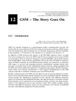
Figure 12.8: Symbol space constellations for GMSK and 8-PSK
even one step further. EDGE replaces the GMSK modulation scheme used in GSM with an
8-PSK (8-Phase Shift Keying) scheme, so that it achieves an approximately three times
higher data rate per time slot and a higher spectral ef®ciency. Using GMSK, one data bit d
i
on average is mapped to one symbol a
i
(see Section 5.2.1); with 8-PSK three data bits d
i
are
combined to one symbol a
i
and transmitted together. Figure 12.8 shows the symbol
constellations in the complex plane and the associated bit sequences. As opposed to
GMSK, 8-PSK does not have a constant envelope and therefore puts higher requirements
on new transceivers in BTSs and MSs.
Furthermore, a link adaptation technique is employed, which dynamically chooses a
modulation and coding scheme according to the current radio channel conditions.
EDGE exists in two variants for GSM: Enhanced Circuit Switched Data (ECSD) for
circuit switched services such as HSCSD, and Enhanced GPRS (EGPRS). More detailed
information can be found in [22,47].
It is interesting to note that both GPRS and EDGE are also being standardized for the North
American cellular network TDMA-136 (GPRS-136 and GPRS-136HS EDGE).
12.4 Supplementary Services in GSM Phase 21
12.4.1 Supplementary Services for Speech
By far the largest part of the supplementary service characteristics known from ISDN have
in one way or another already been implemented in GSM (see Section 4.3). The mobility
of the users, however, creates the need for new supplementary services. Examples of
supplementary services known from ISDN or newly de®ned are mobile access hunting,
short message forwarding, multiple subscriber pro®le, call transfer,orCompletion of
Calls to Busy Subscribers (CCBS).
The example of the CCBS service shows especially clearly how much the role of the HLR
is changing from its original function as a database to a more active role as a service
control component, similar to the Service Control Point (SCP) of the Intelligent Network
(IN). The supplementary service CCBS basically realizes ``call back if busy.'' If a called
subscriber does momentarily not accept a call due to an ongoing connection, the calling
subscriber can activate the supplementary service CCBS which causes the network to
notify him at the end of the called subscriber's ongoing call and automatically set up
the new connection. The subscriber mobility adds more complexity to the implementation
of this service. In the ®xed network, implementation would require the establishment of
queues for call-back requests in the switching center of the calling and called subscribers,
respectively. In a mobile network, this may involve additional switches, because after
activation of the CCBS service, the calling subscriber may be roaming into another switch-
ing center area. If the implementation of the service were only in the MSC, either there
could be a centralized solution, or the queuing lists would have to be forwarded to the new
MSC ± which may even be in another network. The targeted solution is centralized in the
HLR, which has to store the subscriber's callback queues (if existing) in addition to the
current MSC designation. If the mobile station changes the MSC area, the callback queue
is transferred to the new MSC. In this case, therefore, the HLR has to assume an additional
12 GSM ± The Story Goes On
282
server role and perform call control beyond the originally planned restriction to a pure
database function.
12.4.2 Location Service (LCS)
GSM Release 99 introduces a Location Service (LCS) making it possible to determine the
exact location of a mobile station down to a few meters. One of the motivations for this
service has been a law in the USA which demands to locate a person in case of an
emergency call.
From GSM mobility management, the network already knows the current cell of the user
(cell identi®er). However, this location accuracy is not suf®cient in most cases, and there-
fore investigations have been made to ®nd a more sophisticated solution. In the so-called
Time of Arrival (TOA) method, the network listens to handover access bursts of the mobile
station and is then able to triangulate its position. In contrast, using the Enhanced Observed
Time Difference (E-OTD) method, now the mobile stations measure the time difference of
received bursts from different base stations. Both methods only work if a mobile station
has contact to at least three base stations. The accuracy of E-OTD schemes lies between 50
and 125 m, and the one of TOA is worse [12]. E-OTD schemes require a software update
on the mobile equipment as well as modi®cations in the network, whereas for the TOA
method it is mainly suf®cient to modify network components. However, the functionality
of TOA is provided by synchronization of the cellular network (using Global Positioning
System (GPS) or precise clocks at each BTS). This capability is currently not provided in
asynchronous GSM networks. The most precise way to ®nd out the position of a mobile
station is to integrate a GPS receiver into each piece of mobile equipment. The mobile
station then receives its current position from GPS satellites. A substantial disadvantage of
this approach is that mobile stations cannot always have intervisibility with GPS satellites
(e.g. inside buildings). We observe that each of the three methods has its advantages and
disadvantages.
In addition to the technical implementation of the location service, two new network nodes
have been de®ned for this type of service: the Gateway Mobile Location Centre (GMLC)
and the Serving Mobile Location Centre (SMLC). The GMLC acts as an interface to
applications that use the positioning information of users in a speci®c way ± so-called
location-based or location-aware services. Examples are navigation services (such as
``Where is the closest gas station?'') or virtual tourist guides (``What is the building on
my left side?''). A service provider stores e.g. the locations of gas stations and sightseeing
attractions in a database and adds other useful information. At the request of a mobile user,
the provider can get the current position of the user from the GMLC and send back the
requested information. Other location-based applications include location-based charging
(``home zone''), vehicle tracking (e.g. stolen cars), and localized news, weather, and traf®c
information.
12.5 Service Platforms
The procedures for the development of the GSM standards required close cooperation of
12.5 Service Platforms
283
the involved manufacturers and network operators. The international standardization of
services and interfaces led to a set of common successful performance characteristics in
GSM networks, most prominently the international roaming capability. The more a perfor-
mance criterion is standardized, the lower are the costs of development and introduction,
since all manufacturers and operators contribute to paying the costs. On the other hand, the
network operators desire service differentiation to be able to gain competitive advantages.
The standardization of services and service performance criteria reduces the possibility for
differentiation among competitors. Moreover, the time-to-market is often pushed out
because of the prolonged process of standardization.
For these reasons, the service platform concept has been introduced in GSM on both the
network and the terminal side. These platforms offer mechanisms, functions, and protocols
for de®nition and control of services and applications. Those services/applications can be
operator-speci®c, such that an international standardization process is not needed in
general. The required generic functions can be made available in each mobile station
and network node, and they can be used and combined in a ¯exible way for service
execution.
The GSM supplementary services can be regarded as the simplest form of service platform
usage. An extended concept are the so-called service nodes, such as a voice mail server and
an SMS service center. However, both concepts have signi®cant disadvantages: supple-
mentary services are subject to international standardization, and on the other hand these
services might not be available to roaming users in foreign networks, since network
providers are not obligated to implement all supplementary services. The situation is
similar with service nodes, which are often accessible only in the home network. We
conclude that these two types of platforms allow the de®nition of vertical/operator-speci®c
services only in a limited way, and their usage in foreign networks is often not possible or
rather complicated.
An extension of the platform concept, which has been taken up by ETSI in the Phase 21
standardization, attempts to overcome this dilemma. Instead of specifying services and
supplementary services directly or completely, only mechanisms are standardized which
enable introduction of new services. With this approach it is possible to restrict the
implementation of a service to a few switches in the home network of a subscriber,
whereas local (visited) switches have to provide only a ®xed set of basic functions and
the capability to communicate with the home network switch containing service logic.
This group of GSM standards within Phase 21 is known under the name Support of
Operator-Speci®c Services (SOSS), or also as Customized Applications for Mobile
Network Enhanced Logic (CAMEL). The answer on the terminal side is the SIM Applica-
tion Toolkit (SAT) and Mobile Station Execution Environment (MExE). They are
explained in the following.
12.5.1 CAMEL ± GSM and Intelligent Networks
Essentially, CAMEL represents a convergence of GSM and Intelligent Network (IN)
technologies. The fundamental concept of IN is to enable ¯exible implementation, intro-
duction and control of services in public networks and to use the idea of dividing the
12 GSM ± The Story Goes On
284
switching functionality into basic switching functionality, residing in Service Switching
Points (SSPs) and centralized service control functionality, residing in Service Control
Points (SCPs). Both network components communicate with each other over the signaling
network using the generic SS#7 protocol extension called Intelligent Network Application
Part (INAP). This approach enables a centralized, ¯exible, and rapid introduction of new
services [2].
There are already some features in GSM which parallel an intelligent network. Even
though GSM standards use neither IN terminology nor IN protocols, i.e. INAP, the
GSM network structure follows the IN philosophy [41]. In the GSM architecture, the
separation into functional units like MSC and HLR and the consistent use of SS#7 and
its MAP extensions are in conformity with the IN architecture, which is split into SSPs and
SCPs that communicate using INAP.
The philosophy of CAMEL is to proceed with the implementation of services in GSM in a
similar way as in IN. This is re¯ected in separating a set of basic call processing functions
in the MSC or GMSC (which act as SSP), from the intelligent service control functions
(SCP) in the home network of the respective subscriber. The HLR in a GSM network
already has functions similar to the SCP, especially with regard to supplementary services.
Beyond that, the CAMEL approach provides its own dedicated SCPs. Imagine specialized
SCPs for the translation of abbreviated numbers in Virtual Private Networks (VPN) or for
future extended Short Message Services (SMSs). With this con®guration, the service
implementation with its service logic is needed only once, namely in the home network
SCP. The network operator offering the service thus has the sole control over the features
and performance range of the service. Because of the complete range of generic functions
that have to be provided at each SSP (MSC, GMSC, etc.), new services can immediately be
provided in each network, and an uninterrupted service availability is guaranteed for
roaming subscribers. The sole responsibility and control for the introduction of new
services lies in SOSS/CAMEL with the operator of the home network, the contract partner
of the subscriber. This opens new competitive possibilities among network operators.
Operator-speci®c services can be introduced rapidly without having to go through the
standardization process, and yet they are available worldwide.
Figure 12.9 shows the resulting architecture. The CAMEL speci®cation requires a GSM-
speci®c version of IN. Similar to the IN approach, GSM de®nes a basic call processing
function as GSM Service Switching Function (gsmSSF) and a service logic function GSM
Service Control Function (gsmSCF). In addition to the MAP signaling interfaces already
existing in Phase 1 and Phase 2 for communication between visited and home networks
(GMSC, VLR, HLR), new signaling interfaces are needed for communication between
basic switching and service logic in the visited and home networks. For this signaling, a
new application part of SS#7 is being speci®ed, the CAMEL Application Part (CAP),
which assumes the functions similar to INAP. These functions and protocols represent
the basic structure for the realization of intelligent services and their ¯exible introduction.
The prerequisites for CAMEL are the de®nition of a standardized extended call model with
appropriate trigger points, and the speci®cation of the generic range of services which must
be provided by the SSP. More precisely, the new extended call model must also include a
model of subscriber behavior, because besides normal call processing aspects, it also
contains events like location updating. For each subscriber, this behavior model is stored
12.5 Service Platforms
285
in the HLR and supplied from the home network to the currently visited SSP/MSC. In this
way, the SSP/MSC has a set of trigger points with corresponding SCP addresses for each
subscriber roaming in its area. When a trigger condition is satis®ed, the call and transaction
processing in the SSP/MSC is interrupted, and the SCP is noti®ed. The SCP can now
analyze the context and, according to the service implementation, give instructions to the
SSP to perform particular functions. Typical functions the SSP has to implement are call
forwarding, call termination, or other stimuli to the subscriber [45]. Based on this behavior
model and the corresponding control protocol between mobile SSP and home SCP, which
are connected through a set of generic SSP functions, we can expect to see a large variety
of operator-speci®c services in the future.
12.5.2 Service Platforms on the Terminal Side
12.5.2.1 SIM Application Toolkit (SAT)
The SIM Application Toolkit (SAT) has been a further step toward provider-speci®c
vertical services. The GSM SIM card is provided completely by the network operator,
in particular because it contains security functions. From this fact, the basic approach arose
to equip the SIM card with additional, operator-speci®c functions. Without a standardized
interface to the mobile equipment, this was only possible in a very limited manner and only
in close cooperation with equipment manufactures. The SIM Application Toolkit removes
these restrictions by de®ning a standardized interface between mobile equipment and SIM
card. In this way, operator-speci®c applications can run on the SIM card and can thereby
control clearly de®ned, selected functions of the terminal. Corresponding applications can
be carried out in the PLMN or even outside the PLMN on dedicated servers making it
possible to implement completely new services. The communication between the SIM
card application and its counterpart in the network is currently implemented over SMS, but
in the near future other bearer services (in particular GPRS) are also possible. The func-
tions de®ned in the SAT framework can be categorized into SIM data download and
12 GSM ± The Story Goes On
286
Figure 12.9: Functional architecture for CAMEL
proactive SIM. The functional interface between SIM card and terminal is done with
proactive SIM mechanisms. They include:
² display of text
² transmission of SMS messages
² connection setup (speech and data) triggered by the SIM card
² playing of sounds in the mobile equipment
² read-out of local information from the equipment into the SIM card.
With these mechanisms, a broad variety of new features can be offered, for example
download of data to the SIM card. This includes the download of new or existing
commands and applications to be installed. With the toolkit, the SIM card is able to display
new, operator-speci®c menu options to the user, and to read out user actions from the
mobile equipment. Most far-reaching are the functions for call control, where each number
typed in can be analyzed by the SIM card. This allows for operator-speci®c treatment of
telephone numbers, e.g. the mapping of numbers or barring functions. In a further stan-
dardization step, the functions of SAT have been enhanced with security and encryption
mechanisms. SAT-capable mobile stations have been available for a few years.
12.5.2.2 Mobile Station Application Execution Environment (MExE)
Of similar scope is the Mobile Station Execution Environment (MExE), which implements
a generic application platform in the terminal. The most important components are a
virtual machine for execution of Java code and the Wireless Application Protocol
(WAP). Both techniques open the door for a variety of new services and applications.
With a virtual machine running on the mobile terminal, applications can be uploaded and
executed. This demands a high computational effort in the mobile stations. The WAP is
explained in the following.
12.6 Wireless Application Protocol (WAP)
WAP is a major step in building the wireless Internet, where people on-the-go can access the
Internet through their wireless devices to get information such as e-mails, news headlines,
stock reports, map directions and sports scores when they need it and where they need.
Chuck Parish, Founding Member and Chairman (1998±1999) WAP forum
WAP is regarded as an important step of today's GSM networks toward a ``mobile Inter-
net.'' During the last few years, WAP has been developed and standardized by the WAP
Forum [61,63]. This industry consortium was founded by Nokia, Ericsson, Phone.com
(formerly Unwired Planet), and Motorola in December 1997 and has several hundred
members today.
The philosophy of WAP is to transfer Internet content and other interactive services to
mobile stations to make them accessible to mobile users. For this purpose, WAP de®nes a
system architecture, a protocol family, and an application environment for transmission
and display of WWW-like pages for mobile devices.
12.6 Wireless Application Protocol (WAP)
287
The motivation for the development of WAP were the fundamental restrictions posed by
mobile equipment and cellular networks in comparison to PCs and ®xed wired networks.
These are in particular the limited opportunities for display and input (small displays,
number keypad, and no mouse) as well as the limited memory and processing power.
Furthermore, a mobile station's power consumption should be as low as possible. On the
network side, it is clear that the wireless transmission has less bandwidth, a higher bit error
probability, and less stable connections than wired networks.
The protocols and the application environment de®ned for WAP consider these limita-
tions. The protocols of the WAP architecture are basically a modi®cation, optimization,
and enhancement of the Internet Protocol (IP) stack used in the World Wide Web for use
in mobile and wireless environments. WAP focuses on applications tailored to the capabil-
ities of cellular phones and the needs of mobile users. One can say that WAP ``creates an
information Web for cellular phones, distinct from the PC-centric Web'' [24].
12.6.1 Wireless Markup Language (WML)
With respect to the mentioned requirements, the Wireless Markup Language (WML) has
been developed. It represents a pendant to the Hypertext Markup Language (HTML) used
in the World Wide Web. WML is de®ned as a document type of the meta language
Extensible Markup Language (XML). It contains some phone-speci®c tags and requires
only a phone keypad for input. For display of monochrome graphics the Wireless Bitmap
(WBMP) format has been de®ned.
A microbrowser, which is running on each WAP terminal, interprets the received WML
documents and displays their content (text, pictures, links) to the user. Such a microbrow-
ser is also referred to as WML browser and is the pendant to a Web browser used in PCs.
12 GSM ± The Story Goes On
288
Figure 12.10: WAP example
In doing so, the presentation of WML documents is not limited to classical mobile tele-
phones, but there also exist WML browsers for other devices, such as for Personal Digital
Assistants (PDAs) under the operating systems PalmOS, Windows CE, or EPOC systems.
These devices may be linked over infrared or Bluetooth [6] with a GSM mobile station, or
they have their own GSM/GPRS air interface.
WML documents are organized in cards and decks (see Figure 12.10). When a subscriber
chooses a service, a deck of cards is download to the mobile station. The user can then
view these cards with his or her WML browser, make inputs, and navigate between the
cards. Each card is designed for one user interaction.
Figure 12.11 illustrates how an automatic parallel creation of WML and HTML documents
may look like [62]. The World Wide Web Consortium (W3C) currently speci®es the
Extensible Style Language (XSL) [59]. Using XSL style sheets, WML and HTML docu-
ments can be automatically generated from content written in XML.
12.6.2 Protocol Architecture
The WAP protocol architecture is shown in Figure 12.12. As mentioned before, WAP is
based on the WWW protocol stack and adjusts those protocols to the requirements of
wireless transmission and small portable devices.
For applications, a uniform microbrowser environment has been speci®ed: the Wireless
Application Environment (WAE). It comprises the following functionality and formats:
² the Wireless Markup Language (WML),
² a simple script language WMLScript, which is based on JavaScript,
² programming interfaces for control of telephony services (Wireless Telephony Applica-
tion (WTA) interface), and
² data formats for pictures, electronic business cards (vCard), and entries of the phone
directory and calendar (vCalendar).
12.6 Wireless Application Protocol (WAP)
289
Figure 12.11: Generation of WML and HTML documents
The WTA interface allows the microbrowser to interact with telephony functions. For
example, it speci®es how calls are initiated from the microbrowser or how entries from the
phone directory are sent out.
The main task of the Wireless Session Protocol (WSP) is the establishment and termination
of a session between the mobile station and the WAP gateway (Figure 12.14). Thereby,
connection-oriented (over WTP) as well as connectionless (over datagram services, e.g.
WTP) sessions are de®ned. In case a radio connection breaks down, the session can be
stopped for a certain period of time and resumed later.
The Wireless Transaction Protocol (WTP) is a lightweight transaction-oriented protocol.
Its task is to guarantee the reliable exchange of the mobile station's request and the WAP
gateway's response messages (also see Figure 12.14). It thus constitutes the basis for
interactive browsing. WTP includes functions for acknowledgement of messages, retrans-
mission of erroneous or lost messages, and the removal of duplicate messages. In addition,
an acknowledged and an unacknowledged datagram service is de®ned for push services,
where the server can send content to a mobile station without an initiating request from the
mobile user. The server may send an emergency warning, for example.
Optionally, the Wireless Transport Layer Security (WTLS) protocol may be employed. It
is based in the protocol Transport Layer Security (TLS), which is used in the Internet and
was formerly known as Secure Socket Layer (SSL). WTLS offers basic security functions,
such as data integrity, encryption, user identity con®dentiality, and authentication between
server and mobile station. Moreover, protection against denial-of-service attacks is
provided. The functionality of WTLS can be made effective (or not) according to the
application and security of the used network. For example, if an application already
uses strict security techniques, the complete scope of WTLS functions will not be needed.
It is worth mentioning that WTLS can also be used for secure data transfer between two
mobile stations (e.g. for authenticated exchange of electronic business cards).
The WAP transport protocol is known as Wireless Datagram Protocol (WDP). It is for
example used instead of UDP for bearer services that are not based on IP (see Figure
12.12). GSM bearer services for WAP can be either circuit switched data services (e.g.
12 GSM ± The Story Goes On
290
Figure 12.12: Wireless Application Protocol (WAP) ± protocol architecture
SMS) or the General Packet Radio Service (GPRS), where GPRS of course offers faster
data transfer and volume-based billing.
Figure 12.12 indicates that non-WAP protocols can also access speci®c layers of the WAP
stack. Furthermore, not all WAP protocols must be used always. Certain applications may
for example only require the services of WTP and underlying layers. Figure 12.13 gives an
example, where WAP comes into operation over GPRS as a bearer service.
12.6.3 System Architecture
Figure 12.14 gives a schematic illustration of a typical WAP system architecture. The
principle how content is stored in a distributed way within the network and ®nally offered
to the user is similar to the principle of the WWW. Servers store content directly as a WML
document or content is generated with scripts. Mobile stations download these contents
from the server to their microbrowser, which then presents them to the user. In theory, it is
possible to store content in HTML and subsequently convert it to WML, however, in
practice, applications and contents directly offered in WML are suited much better [63].
As shown in Figure 12.14, a WAP Gateway acts as an interface between external servers
and the mobile stations. Its main tasks include:
² conversion of requests from the WAP protocol stack to the WWW protocol stack
(HTTP over TCP/IP) and vice versa (i.e. a protocol gateway functionality)
² encoding and decoding of WML documents into a binary format
The WAP Gateway also represents a proxy server and acts as a cache for frequently
requested contents.
The following example illustrates the transaction procedure between a mobile user, the
WAP Gateway, and an external server: A subscriber intends to view a document which is
offered on a server. His or her WML browser sends a wsp request to the appropriate
12.6 Wireless Application Protocol (WAP)
291
Figure 12.13: Protocol architecture WAP over GPRS (compare with Figure 11.7)
address of the server. The request is forwarded to the WAP Gateway, which then converts
it into an http request and contacts the server. Next, the server transmits the requested
content in WML format to the WAP Gateway, which writes the content into its cache and
sends it in binary-encoded form to the mobile station. The latter presents the ®rst card of
the deck on the microbrowser to the user. If the external server transmitted the document in
HTML format, the gateway would convert it into WML format.
12.6.4 Services and Applications
The ®rst speci®cation of WAP has been released by the WAP Forum in April 1998.
Version 1.1 followed in June 1999 and Version 1.2 in December 1999. WAP terminals
have been introduced around February 1999 for the ®rst time, and today there exists a
broad variety of WAP products: mobile equipment, gateways, development tools, WML
browsers and editors.
Besides the technical implementation in the network and the development of new WAP-
capable mobile equipment, innovative WAP services are in particular in demand. These
days, several information services are offered over WAP. Subscribers can retrieve news,
weather forecasts, stock reports, and local restaurant and event guides with their WAP
phone. Furthermore, mobile e-commerce services (e.g. ticket reservation, mobile banking
and online auctions) become more and more popular. There is much scope left for new
applications. Push services, for example, may transmit important information to mobile
stations without the need to request them actively. Highly interesting are so-called loca-
tion-based services, in which the service knows the current physical location of the user
and may use this information in a speci®c way. Navigation services with displayed maps
12 GSM ± The Story Goes On
292
Figure 12.14: WAP system architecture and request/response transaction
on the browser or virtual tourist guides (``I would like to have information about the
building on the left side.'') are two examples.
The next few years will show whether WAP will win recognition or whether ± with the
next generation of cellular networks with higher data rates ± enhanced mobile stations
(with larger displays, etc.) will communicate over an HTTP-over-TCP/IP protocol stack
and ®nally have access to the worldwide open Internet as we know it from the wired world.
12.7 Beyond GSM: On the Road to UMTS
It could be argued that with all its features and coupled with satellite interworking and near-global
roaming capabilities, GSM will soon ful®l all the goals of the planned third generation system.
William Webb, Smith System Engineering
With all its enhancements, GSM will represent the mainstream of mobile communication
systems for the next several years. However, it is obvious that due to technical and
economical reasons, GSM will be followed by a third generation mobile communication
system. This system, called Universal Mobile Telecommunication System (UMTS) within
ETSI/Europe, is aimed to support a wide range of voice and data services, focussing on
mobile packet switched data services based on IP technology. An important strategic goal
is wireless access to the Internet (see Figure 12.15). Moreover, UMTS will give the mobile
user performance similar to the ®xed network and will stimulate the development of new
mobile multimedia applications. On an international level, i.e. within ITU, the worldwide
family of 3G mobile networks is known as International Mobile Telecommunication 2000
(IMT-2000).
Looking at the rapidly growing number of GSM subscribers (Figure 1.2), it can also be
predicted that any future system must support a very high number of subscribers. For the
year 2002, it is expected that the worldwide number of mobile phones exceeds the number
of ®xed telephones (Figure 12.15). In some countries, e.g. Finland and Japan, this is
12.7 Beyond GSM: On the Road to UMTS
293
Figure 12.15: Million users worldwide (source: Ericsson, August 2000)
already reality today. With respect to the radio spectrum needed for the evolving mass
market and considering the bandwidth requirements of the envisaged broadband services
(up to 2 Mbit/s), the radio interface has to become more spectrum-ef®cient than today.
Therefore, European countries and others have devoted considerable effort to developing
the concepts for a ¯exible and ef®cient next generation of mobile communication systems.
Taking into account the worldwide success of GSM, UMTS will build, as much as possi-
ble, on the existing GSM infrastructure and technology. Overall, it is the intention of all
participants in the UMTS standardization process to enable a smooth transition from
second-generation GSM to third-generation UMTS/IMT-2000 systems. In particular the
GSM service platforms will play a prominent role.
However, UMTS will have a new radio interface, the UMTS Terrestrial Radio Access
(UTRA), using the frequency bands around 2 GHz and new multiple access techniques. At
the World Radio Conference (WRC) in 1992, the decision on the frequency band for IMT-
2000 was made (Figure 12.16): The spectrum 1885±2025 MHz and 2110±2200 MHz has
been reserved. Europe will allocate 1900±1980 MHz, 2010±2025 MHz, and 2110±2170
MHz, which is 155 MHz in total. In addition, 60 MHz (the bands 1980±2010 MHz and
2170±2200 MHz) can be used for the satellite component of UMTS, denoted as Mobile
Satellite System (MSS).
The basic decision on the UMTS multiple access technology was made by ETSI in January
1998. Two techniques are provided:
² For operation in paired bands and Frequency Division Duplex (FDD), UMTS will use
Wideband-CDMA (W-CDMA).
² For operation in an unpaired band, using Time Division Duplex (TDD), the UMTS
system adopts the radio access technique called TD-CDMA, essentially a combination
of TDMA and CDMA.
The UTRA proposal is a compromise between the participating companies, and it has
worldwide support among equipment manufactures and network operators. According to
ETSI, ``the agreed solution offers a competitive continuation for GSM to UMTS.'' A
detailed description can be found in [30].
In parallel to activities in Europe, respective standardization bodies around the world
elaborated additional proposals for IMT-2000. Altogether, a number of 10 proposals
were submitted to ITU for the terrestrial part of IMT-2000. In Japan (ARIB), Korea
(TTA), and USA (T1P1) work was done on different W-CDMA systems. In December
1998, those bodies and ETSI joined to form the Third Generation Partnership Project
(3GPP) [1], which then agreed on a common W-CDMA mode. The IMT-2000 proposals
can thus be grouped into three FDD proposals (W-CDMA, cdma2000 (USA, Korea), and
UWC-139 (USA)) and three TDD proposals (TD-CDMA, TD-SCMDA (China), and
DECT).
In July 1999, the Operators Harmonization Group (OHG) agreed upon a Multi-Carrier
(MC) mode, which also enables operators of IS-95 CDMA networks in North America to
migrate to UMTS. Furthermore, the TD-CDMA and TD-SCDMA speci®cations have been
harmonized, and, ®nally it has been achieved that there will be one worldwide CDMA
standard with three different modes:
12 GSM ± The Story Goes On
294
² a direct sequence mode based on W-CDMA (UTRA FDD),
² a multi-carrier mode based on cdma2000, and
² a TDD mode based on the UTRA proposal TD-CDMA.
Furthermore, the introduction of EDGE (Section 12.3.3) in GSM and in the American
system TDMA-136 results in a harmonized and consistent EDGE/UWC-136 system,
which offers 3G functionality but operates in the ``old'' frequency spectrum. Table 12.3
gives an overview of the 3G mobile systems.
Equally important as the radio interface will be the service concept of UMTS. With respect
to the service aspects, the standard will provide [18] two sorts of mechanisms:
² Mechanisms to enable the creation of supplementary services including the creation and
execution of appropriate MMI (man±machine interface) procedures to the user's term-
inal.
² Mechanisms to permit the de®nition of interworking functions, appropriate for the
12.7 Beyond GSM: On the Road to UMTS
295
Figure 12.16: Frequency bands for UMTS/IMT-2000
Table 12.3: Third generation cellular network family (without DECT)
Type CDMA TDMA
Name W-CDMA cdma2000 TD-CDMA EDGE/UWC-136
Standardization
body
3GPP 3GPP2 3GPP (harmonized
with Chin. TD-SCDMA)
ETSI and
UWCC
Multiple access Direct sequence
CDMA
Multicarrier
CDMA
TD-CDMA TDMA
Duplex FDD FDD TDD FDD