Tài liệu Điện thoại di động băng thông rộng không dây P3 docx
Bạn đang xem bản rút gọn của tài liệu. Xem và tải ngay bản đầy đủ của tài liệu tại đây (1 MB, 10 trang )
respective mapping between logical and transport channels. The TCTF field indicates the
common logical channel type, or if a dedicated logical channel is used.
† UE Id Mux: for dedicated type logical channels, the UE Id field in the MAC header is used
to distinguish between UEs.
† TFC selection: in the downlink, transport format combination selection is done for FACH
and PCH and DSCHs.
† Demultiplex: for TDD operation the demultiplex function is used to separate USCH data
from different UEs, i.e. to be transferred to different MAC-d entities.
† DL code allocation: this function is used to indicate the code used on the DSCH.
Flow control is provided to MAC-d. The RLC provides RLC-PDUs to the MAC, which fit
into the available transport blocks on the transport channels. There is one MAC-c/sh entity in
the UTRAN for each cell.
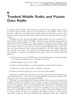
The following functionality is covered by the MAC-d entity at the UTRAN side:
† Channel switching: dynamic transport channel type switching is performed by this entity,
based on decision taken by RRC.
† C/T MUX box: the function includes the C/T field when multiplexing of several dedicated
logical channels onto one transport channel is used.
† Priority setting: this function is responsible for priority setting on data received from
DCCH / DTCH.
† Ciphering: ciphering for transparent mode data to be ciphered is performed in MAC-d.
† Deciphering: deciphering for ciphered transparent mode data is performed in MAC-d.
† DL scheduling/priority handling: in the downlink, scheduling and priority handling of
UMTS Air Interface 51
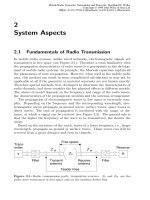
Figure 2.15 UTRAN side MAC architecture. 3GPP TSs and TRs are the property of ARIB, CWTS,
ETSI, T1, TTA and TTC who jointly own copyright in them. They are subject to further modification
and are therefore provided to you ‘as is’ for information purposes only. Further use is strictly prohibited.
transport channels is performed within the allowed transport format combinations of the
TFCS assigned by the RRC.
† Flow control:aflow control function exists toward MAC-c/sh to limit buffering between
MAC-d and MAC-c/sh entities. This function is intended to limit Layer 2 signalling
latency and reduce discarded and retransmitted data as a result of FACH or DSCH conges-
tion.
A MAC-d entity using common channels is connected to a MAC-c/sh entity that handles
the scheduling of the co mmon channels to which the UE is assigned and DL (FACH) priority
identification to MAC-c/sh. A MAC-d entity using downlink shared channel is connected to a
MAC-c/sh entity that handles the shared channels to which the UE is assigned and indicates
the level of priority of each PDU to MAC-c/sh. A MAC-d entity is responsible for mapping
dedicated logical channels onto the available dedicated transport channels or routing the data
received on a DCCH or DTCH to MAC-c/sh. One dedicated logical channel can be mapped
simultaneously on DCH and DSCH. Different scheduling mechanisms apply for DCH and
DSCH. There is one MAC-d entity in the UTRAN for each served UE.
MAC services and functionsServices and functions provided by the MAC sublayer to upper
layers are:
† Data transfer: this service provides unacknowledged transfer of MAC PDUs between
peer MAC entities. This service does not provide any data segmentation. Therefore,
segmentation/reassemble function should be achieved by upper layer.
† Reallocation of radio resources and MAC parameters: this service performs on request
of RRC execution of radio resource reallocation and change of MAC parameters, i.e.
reconfiguration of MAC functions such as change of identity of UE, change of transport
format (combination) sets, change of transport channel type. In TDD mode, in addition,
the MAC can handle resource allocation autonomously.
† Reporting of measurements: local measurements such as traffic volume and quality
indication are reported to RRC.
Logical channels
The MAC layer provides data transfer services on logical channels (Figure 2.10). A set of
logical channel types is defined for different kinds of data transfer services as offered by
MAC. Each logical channel type is defined by what type of information is transferred.
As already described, a general classification of logical channels is in two groups:
† control channels (for the transfer of control plane information).
† traffic channels (for the transfer of user plane information).
Control channels are used for transfer of control plane information only.
† Broadcast Control Channel (BCCH): a downlink channel for broadcasting system
control information.
† Paging Control Channel (PCCH): a downlink channel that transfers paging information.
This channel is used when the network does not know the location cell of the UE, or, the
UE is in the cell connected state (utilizing UE sleep mode procedures).
† Common Control Channel (CCCH): bi-directional channel for transmitting control
Broadband Wireless Mobile: 3G and Beyond52
information between network and UEs. This channel is commonly used by the UEs having
no RRC connection with the network and by the UEs using common transport channels
when accessing a new cell after cell reselection.
† Dedicated Control Channel (DCCH): a point-to-point bi-directional channel that trans-
mits dedicated control information between a UE and the network. This channel is estab-
lished through RRC connection setup procedure.
† Shared Channel Control Channel (SHCCH): bi-directional channel that transmits
control information for uplink and downlink shared channels between network and
UEs. This channel is for TDD only.
† ODMA Common Control Channel (OCCCH): bi-directional channel for transmitting
control information between UEs.
† ODMA Dedicated Control Channel (ODCCH): a point-to-point bi-directional channel
that transmits dedicated control information between UEs. This channel is established
through RRC connection setup procedure.
Traffic channels are used for the transfer of user plane information only.
† Dedicated Traffic Channel (DTCH): a point-to-point channel, dedicated to one UE, for
the transfer of user information. A DTCH can exist in both uplink and downlink.
† ODMA Dedicated Traffic Channel (ODTCH): a point-to-point channel, dedicated to
one UE, for the transfer of user information between UEs. An ODTCH exists in relay link.
† Common Traffic Channel (CTCH): a point-to-multipoint unidirectional channel for
transfer of dedicated user information for all or a group of specified UEs.
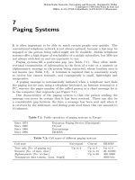
The following connections between logical channels and transport channels exist:
† BCCH is connected to BCH and may also be connected to FACH;
† PCCH is connected to PCH;
† CCCH is connected to RACH and FACH;
† SHCCH is connected to RACH and USCH/FACH and DSCH;
† DTCH can be connected to either RACH and FACH, to RACH and DSCH, to DCH and
DSCH, to a DCH, a CPCH (FDD only) or to USCH (TDD only);
† CTCH is connected to FACH;
† DCCH can be connected to either RACH and FACH, to RACH and DSCH, to DCH and
DSCH, to a DCH, a CPCH (FDD only) to FAUSCH, CPCH (FDD only), or to USCH
(TDD only).
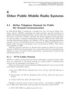
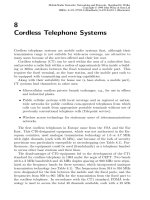
The mappings shown in Figures 2.16 and 2.17 illustrates the mapping from the UE in relay
operation. Note that ODMA logical channels and transport channels are employed only in
relay link transmissions (i.e. not used for uplink or downlink transmissions on the UE-
UTRAN radio interface).
MAC functions The functions of MAC include:
† Mapping between logical channels and transport channels. The MAC is responsible for
mapping of logical channel(s) onto the appropriate transport channel(s).
† Selection of appropriate transport format for each transport channel depending on instan-
taneous source rate. Given the transport format combination set assigned by RRC, MAC
selects the appropriate transport format within an assigned transport format set for each
UMTS Air Interface 53
active transport channel depending on source rate. The control of transport formats ensures
efficient use of transport channels.
† Priority handling between data flows of one UE. When selecting between the transport
format combinations in the given transport format combination set, priorities of the data
flows to be mapped onto the corresponding transport channels can be taken into account.
Priorities are, e.g. given by attributes of radio bearer services and RLC buffer status. The
priority handling is achieved by selecting a transport format combination for which high
priority data is mapped onto L1 with a ‘high bit rate’ transport format, at the same time
letting lower priority data be mapped with a ‘low bit rate’ (could be zero bit rate) transport
format. Transport format selection may also take into account transmit power indication
from Layer 1.
† Priority handling between UEs by means of dynamic scheduling. In order to utilize the
spectrum resources efficiently for bursty transfer, a dynamic scheduling function may be
Broadband Wireless Mobile: 3G and Beyond54
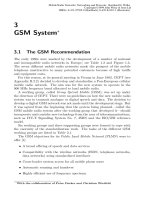
Figure 2.16 Logical channels mapped onto transport channel.
Figure 2.17 Logical channels mapped onto transport channel (ODMA mode only).
applied. MAC realizes priority handling on common and shared transport channels. Note
that for dedicated transport channels, the equivalent of the dynamic scheduling function is
implicitly included as part of the reconfiguration function of the RRC sublayer.
† Identification of UEs on common transport channels. When a particular UE is addressed
on a common downlink channel, or when a UE is using the RACH, there is a need for in-
band identification of the UE. Since the MAC layer handles the access to, and multiplexing
onto, the transport channels, the identification functionality is naturally also placed in
MAC.
† Multiplexing/demultiplexing of higher layer PDUs into/from transport blocks delivered
to/from the physical layer on common transport channels. MAC should support service
multiplexing for common transport channels, since the physical layer does not support
multiplexing of these channels.
† Multiplexing/demultiplexing of higher layer PDUs into/from transport block sets deliv-
ered to/from the physical layer on dedicated transport channels. The MAC allows service
multiplexing for dedicated transport channels. This function can be utilized when several
upper layer services (e.g. RLC instances) can be mapped efficiently on the same transport
channel. In this case the identification of multiplexing is contained in the MAC protocol
control information.
† Traffic volume monitoring. Measurement of traffic volume on logical channels and report-
ing to RRC. Based on the reported traffic volume information, RRC performs transport
channel switching decisions.
† Dynamic Transport Channel type switching. Execution of the switching between common
and dedicated transport channels based on a switching decision derived by RRC.
† Ciphering. This function prevents unauthorized acquisition of data. Ciphering is
performed in the MAC layer for transparent RLC mode.
† Access service class selection for RACH transmission. The RACH resources (i.e. access
slots and preamble signatures for FDD, timeslot and channelization code for TDD) may be
divided between different access service classes in order to provide different priorities of
RACH usage. In addition it is possible for more than one ASC or for all ASCs to be
assigned to the same access slot/signature space. Each access service class will also have a
set of back-off parameters associated with it, some or all of which may be broadcast by the
network. The MAC function applies the appropriate back-off and indicates to the PHY
layer the RACH partition associated to a given MAC PDU transfer.
RLC
RLC architecture
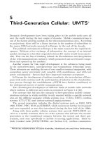
Figure 2.18 gives an overview model of the RLC layer. The figure illustrates the different
RLC peer entities. There is one transmitting and one receiving entity for the transparent mode
service and the unacknowledged mode service and one combined transmitting and receiving
entity for the acknowledged mode service. In [37] the word transmitted is equivalent to
‘submitted to lower layer’ unless otherwise explicitly stated. The dashed lines between the
AM-Entities illustrate the possibility to send the RLC PDUs on separate logical channels, e.g.
control PDUs on one and data PDUs on the other.
Transparent mode entities The transmitting Tr-entity receives SDUs from the higher layers
UMTS Air Interface 55
Broadband Wireless Mobile: 3G and Beyond56
Figure 2.18 Overview model of RLC. 3GPP TSs and TRs are the property of ARIB, CWTS, ETSI,
T1, TTA and TTC who jointly own copyright in them. They are subject to further modification and are
therefore provided to you ‘as is’ for information purposes only. Further use is strictly prohibited.
through the Tr-SAP. RLC might segment the SDUs into appropriate RLC PDUs without
adding any overhead. How to perform the segmentation is decided upon when the service is
established. RLC delivers the RLC PDUs to MAC through either a BCCH, DCCH, PCCH,
SHCCH or a DTCH. The CCCH and SHCCH also uses transparent mode, but only for the
uplink. Which type of logical channel is used depends on whether the higher layer is located
in the control plane (BCCH, DCCH, PCCH, CCCH, SHCCH) or user plane (DTCH).
The Tr-entity receives PDUs through one of the logical channels from the MAC sublayer.
RLC reassembles (if segmentation has been performed) the PDUs into RLC SDUs. How to
perform the reassembling is decided upon when the service is established. RLC delivers the
RLC SDUs to the higher layer through the Tr-SAP.
Unacknowledged mode entities The transmitting UM-entity receives SDUs from the higher
layers. RLC might segment the SDUs into RLC PDUs of appropriate size. The SDU might
also be concatenated with other SDUs. RLC delivers the RLC PDUs to MAC through either a
DCCH, CTCH or a DTCH. The CCCH and SHCCH also uses unacknowledged mode, but
only for the downlink. Which type of logical channel used depends on whether the higher
layer is located in the control plane (CCCH, DCCH, SHCCH) or user plane (CTCH, DTCH).
The receiving UM-entity receives PDUs through one of the logical channels from the MAC
sublayer. RLC removes headers from the PDUs and reassembles the PDUs (if segmentation
has been performed) into RLC SDUs. The RLC SDUs are delivered to the higher layer.
Acknowledged mode entity In the situation where two logical channels are used in the
uplink the first logical channel shall be used for data PDUs and the second logical channel
shall be used for control PDUs. Where one logical channel is used, the RLC PDU size shall be
the same for AMD PDUs and control PDUs.
The transmitting side of the AM-entity receives SDUs from the higher layers. The SDUs
are segmented and/or concatenated to PUs of fixed length. PU length is a semi-static value
that is decided in bearer setup and can only be changed through bearer reconfiguration by
RRC.
For purposes of RLC buffering and retransmission handling, the operation is the same as if
there would be one PU per PDU. For concatenation or padding purposes, bits of information
on the length and extension are inserted into the beginning of the last PU where data from an
SDU is included. Padding can be replaced by piggybacked status information. This includes
setting the poll bit.
If several SDUs fit into one PU, they are concatenated and the appropriate length indicators
are inserted into the beginning of the PU. After that the PUs are placed in the retransmission
buffer and the transmission buffer. One PU is included in one RLC PDU.
The MUX then decides which PDUs and when the PDUs are submitted to a lower layer.
The PDUs are submitted via a function that completes the RLC-PDU header and poten-
tially replaces padding with piggybacked status information. The RLC entity shall assume a
PDU to be transmitted when the PDU is submitted to lower layer.
The ciphering is applied only for AMD PDUs. The fixed 2-octet AMD PDU header is not
ciphered. Piggybacked and padding parts of AMD PDU, when existing, are ciphered. The
other Control PDUs (e.g. STATUS, RESET, and RESET ACK PDU) shall not be ciphered.
When the piggybacking mechanism is applied, the padding is replaced by control informa-
tion, in order to increase the transmission efficiency making possible a faster message
exchange between the peer to peer RLC entities. The piggybacked control information is
UMTS Air Interface 57
not saved in any retransmission buffer. The piggybacked control information is contained in
the piggybacked STATUS PDU, which is in turn included into the AMD-PDU. The piggy-
backed STATUS PDUs will be of variable size in order to match with the amount of free
space in the AMD PDU.
The retransmission buffer also receives acknowledgements from the receiving side, which
are used to indicate retransmissions of PUs and when to delete a PU from the retransmission
buffer.
The receiving side of the AM-entity receives PDUs through one of the logical channels
from the MAC sublayer. The RLC-PDUs are expanded into separate PUs and potential
piggybacked status information is extracted. The PUs are placed in the receiver buffer
until a complete SDU has been received. The receiver buffer requests retransmissions of
PUs by sending negative acknowledgements to the peer entity. After that the headers are
removed from the PDUs and the PDUs are reassembled into a SDU. Finally the SDU is
delivered to the higher layer. The receiving side also receives acknowledgements from the
peer entity. The acknowledgements are passed to the retransmission buffer on the transmit-
ting side.
RLC services and functions
The services provided to the upper layer are as follows:
† RLC connection establishment/release: this service performs establishment/release of
RLC connections.
† Transparent data transfer: this service transmits higher layer PDUs without adding any
protocol information, possibly including segmentation/reassemble functionality.
† Unacknowledged data transfer: this service transmits higher layer PDUs without guar-
anteeing delivery to the peer entity. The unacknowledged data transfer mode has the
following characteristics:
† SUBDetection of erroneous data: the RLC sublayer shall deliver only those SDUs to the
receiving higher layer that are free of transmission errors by using the sequence-number
check function;
† SUBThe RLC sublayer shall deliver each SDU only once to the receiving upper layer
using duplication detection function;
† SUBThe receiving RLC sublayer entity shall deliver a SDU to the higher layer receiving
entity as soon as it arrives at the receiver.
† Acknowledged data transfer. This service transmits higher layer PDUs and guarantees
delivery to the peer entity. In case RLC is unable to deliver the data correctly, the user of
RLC at the transmitting side is notified. For this service, both in-sequence and out-of-
sequence delivery are supported. In many cases a higher layer protocol can restore the
order of its PDUs. As long as the out-of-sequence properties of the lower layer are known
and controlled (i.e. the higher layer protocol will not immediately request retransmission
of a missing PDU) allowing out-of-sequence delivery can save memory space in the
receiving RLC. The acknowledged data transfer mode has the following characteristics:
† SUBError-free delivery: error-free delivery is ensured by means of retransmission. The
receiving RLC entity delivers only error-free SDUs to the higher layer.
† SUBUnique delivery: the RLC sublayer shall deliver each SDU only once to the receiving
upper layer using duplication detection function.
† SUBIn-sequence delivery: RLC sublayer shall provide support for in-order delivery of
Broadband Wireless Mobile: 3G and Beyond58
SDUs, i.e. RLC sublayer should deliver SDUs to the receiving higher layer entity in the
same order as the transmitting higher layer entity submits them to the RLC sublayer.
† SUBOut-of-sequence delivery: as an alternative to in-sequence delivery, it shall also be
possible to allow that the receiving RLC entity delivers SDUs to higher layer in different
order than submitted to RLC sublayer at the transmitting side.
† QoS setting: the retransmission protocol shall be configurable by Layer 3 to provide
different levels of QoS. This can be controlled.
† Notification of unrecoverable errors:RLC notifies the upper layer of errors that cannot
be resolved by RLC itself by normal exception handling procedures, e.g. by adjusting the
maximum number of retransmissions according to delay requirements.
There is a single RLC connection per radio bearer. The RLC functionality is described in
the following items:
† Segmentation and reassemble: this function performs segmentation/reassemble of vari-
able-length higher layer PDUs into/from smaller RLC Payload Units (PUs). The RLC
PDU size is adjustable to the actual set of transport formats.
† Concatenation: if the contents of an RLC SDU do not fill an integer number of RLC PUs,
the first segment of the next RLC SDU may be put into the RLC PU in concatenation with
the last segment of the previous RLC SDU.
† Padding: when concatenation is not applicable and the remaining data to be transmitted
does not fill an entire RLC PDU of given size, the remainder of the data field shall be filled
with padding bits.
† Transfer of user data: this function is used for conveyance of data between users of RLC
services. RLC supports acknowledged, unacknowledged and transparent data transfer.
QoS setting controls transfer of user data.
† Error correction: this function provides error correction by retransmission (e.g. Selective
Repeat, Go Back N, or a Stop-and-Wait ARQ) in acknowledged data transfer mode.
† In-sequence delivery of higher layer PDUs: this function preserves the order of higher
layer PDUs that were submitted for transfer by RLC using the acknowledged data transfer
service. If this function is not used, out-of-sequence delivery is provided.
† Duplicate detection: this function detects duplicated received RLC PDUs and ensures
that the resultant higher Layer PDU is delivered only once to the upper layer.
† Flow control: this function allows an RLC receiver to control the rate at which the peer
RLC transmitting entity may send information.
† Sequence number check (unacknowledged data transfer mode): this function guaran-
tees the integrity of reassembled PDUs and provides a mechanism for the detection of
corrupted RLC SDUs through checking sequence number in RLC PDUs when they are
reassembled into a RLC SDU. A corrupted RLC SDU will be discarded.
† Protocol error detection and recovery: this function detects and recovers from errors in
the operation of the RLC protocol.
† Ciphering: this function prevents unauthorized acquisition of data. Ciphering is
performed in RLC layer for non-transparent RLC mode.
† Suspend/resume function: suspension and resumption of data transfer as in e.g. LAPDm
(cf. GSM 04.05).
UMTS Air Interface 59
PDCP
PDCP architecture
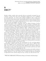
Figure 2.19 shows the model of the Packet Data Convergence Protocol (PDCP) [38] within
the UTRAN protocol architecture. Every PDCP-SAP uses exactly one PDCP entity. Each
PDCP entity uses none, one or several header compression algorithm types.
PDCP services and functions
† PDCP services provided to upper layers:
† SUBTransmission and reception of network PDUs in acknowledged, unacknowledged and
transparent RLC mode.
† PDCP functions:
† SUBMapping of Network PDUs from one network protocol to one RLC entity.
† SUBCompression in the transmitting entity and decompression in the receiving entity of
redundant Network PDU control information (header compression/ decompression). This
may include TCP/IP header compression and decompression.
Broadband Wireless Mobile: 3G and Beyond60
Figure 2.19 PDCP structure. 3GPP TSs and TRs are the property of ARIB, CWTS, ETSI, T1, TTA
and TTC who jointly own copyright in them. They are subject to further modification and are therefore
provided to you ‘as is’ for information purposes only. Further use is strictly prohibited.