Tài liệu Designing with FPGAs and CPLDs- P2 ppt
Bạn đang xem bản rút gọn của tài liệu. Xem và tải ngay bản đầy đủ của tài liệu tại đây (164.42 KB, 30 trang )
14 Chapter 1: Prehistory: Programmable Logic to ASICs
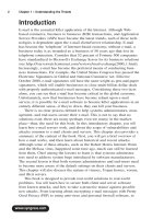
Within the core array are basic
cells, or gates, each consisting of
some small number of transistors
that are not connected. In fact, none
of the transistors on the gate array
are initially connected at all. The
reason for this is that the connection
is determined completely by the
design that you implement. Once
given a design, the layout software
figures out which transistors to con-
nect by placing metal connections
on top of the die as shown. First, the
low level functions are connected
together. For example, six transis-
tors could be connected to create a
D flip-flop. These six transistors would be located physically very close to each
other. After the low level functions have been routed, they would in turn be con-
nected together. The software would continue this process until the entire design
is complete.
The ASIC vendor manufactures many unrouted die that contain the arrays of
gates and that it can use for any gate array customer. An integrated circuit con-
sists of many layers of materials, including semiconductor material (e.g., sili-
con), insulators (e.g., oxides), and conductors (e.g., metal). An unrouted die is
processed with all of the layers except for the final metal layers that connect the
gates together. Once the design is complete, the vendor simply needs to add the
last metal layers to the die to create your chip, using photo masks for each metal
layer. For this reason, it is sometimes referred to as a “masked gate array” to dif-
ferentiate it from a field programmable gate array.
The advantage of a gate array is that the internal circuitry is very fast; the cir-
cuit is dense, allowing lots of functionality on a die; and the cost is low for high
volume production. Gate arrays can reach clock frequencies of hundreds of
megahertz with densities of millions of gates. The disadvantage is that it takes
time for the ASIC vendor to manufacture and test the parts. Also, the customer
incurs a large charge up front, called a non-recurring engineering (NRE)
expense, which the ASIC vendor charges to begin the entire ASIC process. And
if there’s a mistake, it’s a long, expensive process to fix it and manufacture new
ASICs.
Figure 1.9 Masked Gate Array architecture
Please purchase PDF Split-Merge on www.verypdf.com to remove this watermark.
CPLDs and FPGAs 15
1.5 CPLDs and FPGAs
Ideally, hardware
designers wanted
something that gave
them the advantages
of an ASIC — circuit
density and speed —
but with the shorter
turnaround time of a
programmable
device. The solution
came in the form of
two new devices —
the complex pro-
grammable logic device (CPLD) and the field programmable gate array (FPGA).
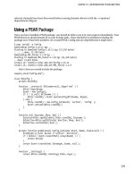
Figure 1.10 shows how CPLDs and FPGAs bridge the gap between PALs and
gate arrays. All of the inherent advantages of PALs, shown on the left of the dia-
gram, and all of the inherent advantages of gate array ASICS, shown on the
right of the diagram, were combined. CPLDs are as fast as PALs but more com-
plex. FPGAs approach the complexity of gate arrays but are still programmable.
CPLD architectures and technologies are the same as those for PALs. FPGA
architecture is similar to those of gate array ASICs.
1.6 Summary
Several programmable and semi-custom technologies preceded the development
of CPLDs and FPGAs. This chapter started by reviewing the architecture, prop-
erties, uses, and tradeoffs of the various programmable devices (PROMS, PLAS,
and PALs) that were in use before CPLDs and FPGAs. Later the chapter
described ASICs and examined the contribution of a specific type of ASIC archi-
tecture called a gate array. The architecture, properties, uses, and tradeoffs of
the gate array were discussed. Finally, CPLDs and FPGAs were introduced,
briefly, as programmable chip solutions that filled the gap between programma-
ble devices and gat array ASICs.
PALs Gate Arrays
CPLDs and FPGAs
• Short lead time
• Programmable
• No NRE changes
• High density
• Can implement many
logic functions
• Relatively fast
Figure 1.10 The evolution of CPLDs and FPGAs
Please purchase PDF Split-Merge on www.verypdf.com to remove this watermark.
16 Chapter 1: Prehistory: Programmable Logic to ASICs
Exercises
1. What does the term ASIC stand for?
(a) Application standard integrated chip
(b) Applied system integrated circuit
(c) Application specific integrated circuit
2. Match each programmable device with its description.
3. Choose the correct device for each statement — PALs or ASICs.
(a) ________ have a short lead time.
(b) ________ are high-density devices.
(c) ________ can implement very complex functions.
(d) ________ do not have NRE charges.
(e) ________ are programmable.
(a) PROM (A) A memory device that can be programmed once and read
many times.
(b) PLA (B) A logic device that can be used to design large functions like an
ASIC, except that it can be programmed quickly and inexpen-
sively.
(c) PAL (C) A logic device that is made up of many PAL devices.
(d) CPLD (D) A logic device with a large AND plane and a large OR plane
for implementing different combinations of Boolean logic.
(e) FPGA (E) A logic device with a large AND plane and a small, fixed num-
ber of OR gates for implementing Boolean logic and state
machines.
Please purchase PDF Split-Merge on www.verypdf.com to remove this watermark.
17
Chapter 2
Complex Programmable Logic
Devices (CPLDs)
Complex Programmable Logic Devices are exactly what they claim to be: logic
devices that are complex and programmable. There are two main engineering
features to understand about CPLDs that separate them from their cousins,
FPGAs. One feature is the internal architecture of the device and how this archi-
tecture implements various logic functions. The second feature is the semicon-
ductor technology that allows the devices to be programmed and allows various
structures in the device to be connected.
Objectives
This chapter focuses on the architecture and technologies of CPLDs. This chap-
ter should help you:
• Understand the internal architecture of CPLDs
• Gain knowledge of the technologies used for programming and con-
necting internal blocks of CPLDs
• Learn the advantages and tradeoffs of different architectures and tech-
nologies
In this chapter
• CPLD Architectures
• Function Blocks
• I/O Blocks
• CPLD Technology and Pro-
grammable Elements
• CPLD Selection Criteria
• Example CPLD Families
Please purchase PDF Split-Merge on www.verypdf.com to remove this watermark.
18 Chapter 2: Complex Programmable Logic Devices (CPLDs)
2.1 CPLD Architectures
Essentially, CPLDs are designed to appear just like a large number of PALs in a
single chip, connected to each other through a crosspoint switch. This architec-
ture made them familiar to their target market — PC board designers who were
already designing PALs in their boards. Many CPLDs were used to simply com-
bine multiple PALs in order to save real estate on a PC board. CPLDs use the
same development tools and programmers as PALs, and are based on the same
technologies as PALs, but they can handle much more complex logic and more
of it.
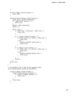
The diagram in
Figure 2.1 shows the
internal architecture
of a typical CPLD.
Although each man-
ufacturer has a dif-
ferent variation, in
general they are all
similar in that they
consist of function
blocks, input/output
blocks, and an inter-
connect matrix.
2.2 Function Blocks
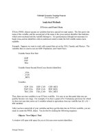
A typical function block is shown in Figure 2.3.
Notice the similarity to the PAL architecture
with its wide AND plane and fixed number of
OR gates. The AND plane is shown by the
crossing wires on the left. The AND plane can
accept inputs from the I/O blocks, other func-
tion blocks, or feedback from the same func-
tion block. Programming elements at each
intersection in the AND plane allow perpendicular traces to be connected or left
open, creating “product terms,” which are multiple signals ANDed together,
just like in a PAL. The product terms are then ORed together and sent straight
out of the block, or through a clocked flip-flop. The Boolean equation in Figure
2.2 has four product terms.
There are also multiplexers in the diagram, shown as boxes labeled M1, M2,
and M3. Each mux has an FET transistor beneath it, representing a programmable
Interconnect
Matrix
I/O I/O
FB
FB
FB
FB
FB
FB
FB
FB
Figure 2.1 CPLD Architecture (courtesy of Altera Corporation)
xyz = a1 & b1 & c2
| !a1 & b1 & !c2
| a1 & !b1
| a1 & !c2
Figure 2.2 Boolean equation
with four product terms
Please purchase PDF Split-Merge on www.verypdf.com to remove this watermark.
Function Blocks 19
element attached to the select line. In other words, the mux can be programmed to
output one of the inputs. M1 is the “Clear Select” because it selects the signal that
is used to clear the flip-flop. The M2 mux is labeled “Clock/Enable Select” because
its two outputs are programmed to control the clock and clock enable input to the
flip-flop. The M3 mux is labeled “Register Bypass” because it is programmed to
determine whether the output of the functional block is a registered signal (i.e., is
the output of a flip-flop) or a combinatorial signal (i.e., is the output of combinato-
rial logic).
Many CPLDs include additional, specialized logic. This particular block
includes an exclusive OR, which can be effectively bypassed by programming
one input to always be a 0. An XOR can be a nice gate to have because it is oth-
erwise difficult to implement this function in a PAL. Exclusive ORs are used to
easily generate parity in a bus for simple error detection.
Though not explicitly shown in Figure 2.3, each functional block would have
many OR gates, logic gates, muxes, and flip-flops. Usually, the function blocks
are designed to be similar to existing PAL architectures, such as the 22V10, so
that the designer can use familiar tools to design them. They may even be able to
fit older PAL designs into the CPLD without changing the design.
Logic Array
Programmable
Interconnect
Signals
16 Espander
Product Terms
Shared
Logic
Global
Clear
Global
Clock
Clear
Select
Clock/
Enbable
Select
VCC
Register
Bypass
to PIA
to I/O
M1
M2
M3
PRN
CLRN
DQ
ENA
Figure 2.3 CPLD function block (courtesy of Altera Corporation)
Please purchase PDF Split-Merge on www.verypdf.com to remove this watermark.
20 Chapter 2: Complex Programmable Logic Devices (CPLDs)
2.3 I/O Blocks
Figure 2.4 shows a typical I/O block of a
CPLD. The I/O block is used to drive signals
to the pins of the CPLD device at the appro-
priate voltage levels (e.g., TTL, CMOS,
ECL, PECL, or LVDS). The I/O block typi-
cally allows each I/O pin to be individually
configured for input, output, or bi-direc-
tional operation. The I/O pins have a
tri-state output buffer that can be controlled
by global output enable signals or directly
connected to ground or VCC. Each output
pin can also be configured to be open drain.
In addition, outputs can often be pro-
grammed to drive different voltage levels,
enabling the CPLD to be interfaced to many
different devices.
One particularly useful feature in high speed CPLDs is the ability to control
the rise and fall rates of the output drivers by using a slew rate control. Design-
ers can configure the output buffers for fast rise and fall times or for slow transi-
tion times. An advantage of the fast speed of these devices is less delay through
the logic. A disadvantage of faster transition is times that they can cause over-
shoot and undershoot, which can potentially damage the device that the CPLD
is driving. Also, fast transitions introduce noise, which can create problems. By
programming the slew rate of the output buffer to a relatively slow transition,
you can preserve the small logic delays of the device while avoiding undershoot,
overshoot, and noise problems.
The input signal from the I/O block goes into the switch matrix in order to be
routed to the appropriate functional block. In some architectures, particular
inputs have direct paths to particular functional blocks in order to lower the
delay on the input, reducing the signal setup time. In most architectures, specific
pins of the device connect to specific I/O blocks that can drive global signals like
reset and clock. This means that only certain pins of the device can be used to
drive these global signals. This is particularly important for clock signals, as
described in the next section.
2.4 Clock Drivers
As Section 5.3 (in Chapter 5) explains, synchronous design is the only accepted
design methodology that will ensure that a CPLD-based design is reliable over
VCC
GND
From
Switch
Matrix
From FB
Open-Drain Output
Slow-Rate Control
To FB or
Switch
Matrix
Figure 2.4 CPLD input/output
block (courtesy of Altera
Corporation)
Please purchase PDF Split-Merge on www.verypdf.com to remove this watermark.
Interconnect 21
its lifetime. In order to design synchronous CPLDs, the clock signal must arrive
at each flip-flop in the design at about the same time and with very little delay
from the input pin. In order to accomplish this, special I/O blocks have clock
drivers that use very fast input buffers and which drive the input clock signal
onto an internal clock tree. The clock tree is so named because it resembles a
tree, with each branch driving the clock input of a fixed number of flip-flops.
The clock driver is designed to drive the entire tree very quickly. The trees are
designed to minimize the skew between clock signals arriving at different
flip-flops throughout the device. Each branch of the tree is of approximately
equal length, or if not, internal buffers are used to balance the skew along the
different branches. It is important that clock signals are only driven through the
clock input pins that connect to these special drivers.
In large devices, there may be several clock input pins connected to different
clock drivers. This feature helps in designs that use multiple clocks. You need to
have at least as many clock drivers in the CPLD as you need clocks in your
design. Also, the different clocks must be considered to be asynchronous with
respect to each other, because the CPLD vendor does not typically guarantee
skew between multiple clocks. Signals clocked by one clock will need to be syn-
chronized with the other clock before use by any logic clocked by the second
clock. For more information on synchronous design and synchronizing asyn-
chronous signals, see Section 5.3.
2.5 Interconnect
The CPLD interconnect is a very large programmable switch matrix that allows
signals from all parts of the device to go to all other parts of the device. Figure
2.5 shows the architecture of the switch matrix. The switch matrix takes the
outputs of the functional blocks and is programmed to send those outputs to
functional blocks. This way, the designer can route any output signal to any des-
tination.
Please purchase PDF Split-Merge on www.verypdf.com to remove this watermark.
22 Interconnect
Computing Parity Without Exclusive OR
The Boolean expression for generating even parity for a bus is shown in the following equation:
parity = a0 ^ a1 ^ a2 ^ a3 ^ a4 ^ a5 ^ a6 ^ a7
If we implement this equation using AND and OR logic, the result is
parity = a0 & !a1 & !a2 & !a3 & !a4 & !a5 & !a6 & !a7
| !a0 & a1 & !a2 & !a3 & !a4 & !a5 & !a6 & !a7
| a0 & a1 & a2 & !a3 & !a4 & !a5 & !a6 & !a7
| !a0 & !a1 & a2 & !a3 & !a4 & !a5 & !a6 & !a7
| a0 & !a1 & a2 & a3 & !a4 & !a5 & !a6 & !a7
| !a0 & a1 & a2 & a3 & !a4 & !a5 & !a6 & !a7
| a0 & a1 & !a2 & a3 & !a4 & !a5 & !a6 & !a7
| !a0 & !a1 & !a2 & a3 & !a4 & !a5 & !a6 & !a7
| a0 & !a1 & !a2 & a3 & a4 & !a5 & !a6 & !a7
| !a0 & a1 & !a2 & a3 & a4 & !a5 & !a6 & !a7
| a0 & a1 & a2 & a3 & a4 & !a5 & !a6 & !a7
| !a0 & !a1 & a2 & a3 & a4 & !a5 & !a6 & !a7
| a0 & !a1 & a2 & !a3 & a4 & !a5 & !a6 & !a7
| !a0 & a1 & a2 & !a3 & a4 & !a5 & !a6 & !a7
| a0 & a1 & !a2 & !a3 & a4 & !a5 & !a6 & !a7
| !a0 & !a1 & !a2 & !a3 & a4 & !a5 & !a6 & !a7
| a0 & !a1 & !a2 & !a3 & a4 & a5 & !a6 & !a7
| !a0 & a1 & !a2 & !a3 & a4 & a5 & !a6 & !a7
| a0 & a1 & a2 & !a3 & a4 & a5 & !a6 & !a7
| !a0 & !a1 & a2 & !a3 & a4 & a5 & !a6 & !a7
| a0 & !a1 & a2 & a3 & a4 & a5 & !a6 & !a7
| !a0 & a1 & a2 & a3 & a4 & a5 & !a6 & !a7
| a0 & a1 & !a2 & a3 & a4 & a5 & !a6 & !a7
| !a0 & !a1 & !a2 & a3 & a4 & a5 & !a6 & !a7
| a0 & !a1 & !a2 & a3 & !a4 & a5 & !a6 & !a7
| !a0 & a1 & !a2 & a3 & !a4 & a5 & !a6 & !a7
| a0 & a1 & a2 & a3 & !a4 & a5 & !a6 & !a7
| !a0 & !a1 & a2 & a3 & !a4 & a5 & !a6 & !a7
| a0 & !a1 & a2 & !a3 & !a4 & a5 & !a6 & !a7
| !a0 & a1 & a2 & !a3 & !a4 & a5 & !a6 & !a7
| a0 & a1 & !a2 & !a3 & !a4 & a5 & !a6 & !a7
| !a0 & !a1 & !a2 & !a3 & !a4 & a5 & !a6 & !a7
Please purchase PDF Split-Merge on www.verypdf.com to remove this watermark.
CPLD Technology and Programmable Elements 23
One advantage of the
CPLD switch matrix routing
scheme is that delays
through the chip are deter-
ministic. Designers can
determine the delay for any
signal by computing the
delay through functional
blocks, I/O blocks, and the
switch matrix. All of these
delays are fixed, and delays
due to routing the signal
along the metal traces are
negligible. If the logic for a
particular function is com-
plex, it may require several functional blocks, and thus several passes through
the switch matrix, to implement. Designers can bery easily calculate delays from
input pins to output pins of a CPLD by using a few worst-case timing numbers
supplied by the CPLD vendor. This contrasts greatly with FPGAs, which have
very unpredictable and design-dependent timing due to their routing mecha-
nism.
2.6 CPLD Technology and Programmable Elements
Different manufacturers use different technologies to implement the program-
mable elements of a CPLD. The common technologies are EPROM, EEPROM,
and Flash EPROM. These technologies are versions of the technologies that
were used for the simplest programmable devices, PROMs, which we discussed
earlier. In functional blocks and I/O blocks, single bits are programmed to turn
specific functions on and off, Figure 2.3 and Figure 2.4 show. In the switch
matrix, single bits are programmed to control connections between signals using
a multiplexer, as shown in Figure 2.5.
When PROM technology is used for these devices, they can be programmed
only once. More commonly these days, manufacturers use EPROM, EEPROM,
or Flash EPROM, allowing the devices to be erased and reprogrammed.
Erasable technology can also allow in-system programmability of the device.
For CPLDs with this capability, a serial interface on the chip is used to send new
programming data into the chip after it is soldered into a PC board and while
the system is operating. Typically this serial interface is the industry-standard
4-pin Joint Test Action Group (JTAG) interface (IEEE Std. 1149.1-1990).
Outputs to FBs
Switch Matrix
Inputs
to FBs
Figure 2.5 CPLD switch matrix (courtesy of Altera
Corporation)
Please purchase PDF Split-Merge on www.verypdf.com to remove this watermark.
24 CPLD Technology and Programmable Elements
| a0 & !a1 & !a2 & !a3 & !a4 & a5 & a6 & !a7
| !a0 & a1 & !a2 & !a3 & !a4 & a5 & a6 & !a7
| a0 & a1 & a2 & !a3 & !a4 & a5 & a6 & !a7
| !a0 & !a1 & a2 & !a3 & !a4 & a5 & a6 & !a7
| a0 & !a1 & a2 & a3 & !a4 & a5 & a6 & !a7
| !a0 & a1 & a2 & a3 & !a4 & a5 & a6 & !a7
| a0 & a1 & !a2 & a3 & !a4 & a5 & a6 & !a7
| !a0 & !a1 & !a2 & a3 & !a4 & a5 & a6 & !a7
| a0 & !a1 & !a2 & a3 & a4 & a5 & a6 & !a7
| !a0 & a1 & !a2 & a3 & a4 & a5 & a6 & !a7
| a0 & a1 & a2 & a3 & a4 & a5 & a6 & !a7
| !a0 & !a1 & a2 & a3 & a4 & a5 & a6 & !a7
| a0 & !a1 & a2 & !a3 & a4 & a5 & a6 & !a7
| !a0 & a1 & a2 & !a3 & a4 & a5 & a6 & !a7
| a0 & a1 & !a2 & !a3 & a4 & a5 & a6 & !a7
| !a0 & !a1 & !a2 & !a3 & a4 & a5 & a6 & !a7
| a0 & !a1 & !a2 & !a3 & a4 & !a5 & a6 & !a7
| !a0 & a1 & !a2 & !a3 & a4 & !a5 & a6 & !a7
| a0 & a1 & a2 & !a3 & a4 & !a5 & a6 & !a7
| !a0 & !a1 & a2 & !a3 & a4 & !a5 & a6 & !a7
| a0 & !a1 & a2 & a3 & a4 & !a5 & a6 & !a7
| !a0 & a1 & a2 & a3 & a4 & !a5 & a6 & !a7
| a0 & a1 & !a2 & a3 & a4 & !a5 & a6 & !a7
| !a0 & !a1 & !a2 & a3 & a4 & !a5 & a6 & !a7
| a0 & !a1 & !a2 & a3 & !a4 & !a5 & a6 & !a7
| !a0 & a1 & !a2 & a3 & !a4 & !a5 & a6 & !a7
| a0 & a1 & a2 & a3 & !a4 & !a5 & a6 & !a7
| !a0 & !a1 & a2 & a3 & !a4 & !a5 & a6 & !a7
| a0 & !a1 & a2 & !a3 & !a4 & !a5 & a6 & !a7
| !a0 & a1 & a2 & !a3 & !a4 & !a5 & a6 & !a7
| a0 & a1 & !a2 & !a3 & !a4 & !a5 & a6 & !a7
| !a0 & !a1 & !a2 & !a3 & !a4 & !a5 & a6 & !a7
| a0 & !a1 & !a2 & !a3 & !a4 & !a5 & a6 & a7
| !a0 & a1 & !a2 & !a3 & !a4 & !a5 & a6 & a7
| a0 & a1 & a2 & !a3 & !a4 & !a5 & a6 & a7
| !a0 & !a1 & a2 & !a3 & !a4 & !a5 & a6 & a7
| a0 & !a1 & a2 & a3 & !a4 & !a5 & a6 & a7
Computing Parity Without Exclusive OR (Continued)
Please purchase PDF Split-Merge on www.verypdf.com to remove this watermark.
Embedded Devices 25
2.7 Embedded Devices
A relatively recent addition to the architecture of many CPLD devices is embed-
ded devices, which consists of large devices integrated into the CPLD. These
devices can be connected to the rest of the CPLD via the switch matrix. The
availability of embedded devices brings designers closer to the concept of a sys-
tem on a programmable chip (SOPC). Engineers can now move the processors,
memory, and other complex standard devices that would normally be on a cir-
cuit board along with a CPLD directly into the CPLD.
The main advantages of embedded devices are cost reduction, reduced circuit
board space, and often lower power consumption. A disadvantage is that it
tends to tie your design into a specific CPLD offered by a single CPLD vendor
because different vendors supply different embedded devices in their CPLDs, if
they offer them at all.
The number and kinds of embedded devices that are being integrated into
CPLDs are increasing annually. Currently, these devices include
• SRAM memories
• Flash memories
Table 2.1 JTAG signals
Signal Description
TCK Test Clock Input
A clock signal used to shift test instructions, test data, and control inputs
into the chip on the rising edge and to shift the output data from the chip
on the falling edge.
TMS Test Mode Select
Serial input for controlling the internal JTAG state machine. The state of
this bit on the rising edge of each clock determines which actions the chip
is to take.
TDI Test Data Input
Serial input for instructions and program data. Data is captured on the
rising edge of the clock.
TDO Test Data Output
Serial output for test instruction and program data from the chip. Valid
data is driven out on the falling edge of the clock.
TRST Test Reset Input (Extended JTAG only)
An asynchronous active low reset that is used to initialize the JTAG con-
troller.
Please purchase PDF Split-Merge on www.verypdf.com to remove this watermark.
26 Embedded Devices
| !a0 & a1 & a2 & a3 & !a4 & !a5 & a6 & a7
| a0 & a1 & !a2 & a3 & !a4 & !a5 & a6 & a7
| !a0 & !a1 & !a2 & a3 & !a4 & !a5 & a6 & a7
| a0 & !a1 & !a2 & a3 & a4 & !a5 & a6 & a7
| !a0 & a1 & !a2 & a3 & a4 & !a5 & a6 & a7
| a0 & a1 & a2 & a3 & a4 & !a5 & a6 & a7
| !a0 & !a1 & a2 & a3 & a4 & !a5 & a6 & a7
| a0 & !a1 & a2 & !a3 & a4 & !a5 & a6 & a7
| !a0 & a1 & a2 & !a3 & a4 & !a5 & a6 & a7
| a0 & a1 & !a2 & !a3 & a4 & !a5 & a6 & a7
| !a0 & !a1 & !a2 & !a3 & a4 & !a5 & a6 & a7
| a0 & !a1 & !a2 & !a3 & a4 & a5 & a6 & a7
| !a0 & a1 & !a2 & !a3 & a4 & a5 & a6 & a7
| a0 & a1 & a2 & !a3 & a4 & a5 & a6 & a7
| !a0 & !a1 & a2 & !a3 & a4 & a5 & a6 & a7
| a0 & !a1 & a2 & a3 & a4 & a5 & a6 & a7
| !a0 & a1 & a2 & a3 & a4 & a5 & a6 & a7
| a0 & a1 & !a2 & a3 & a4 & a5 & a6 & a7
| !a0 & !a1 & !a2 & a3 & a4 & a5 & a6 & a7
| a0 & !a1 & !a2 & a3 & !a4 & a5 & a6 & a7
| !a0 & a1 & !a2 & a3 & !a4 & a5 & a6 & a7
| a0 & a1 & a2 & a3 & !a4 & a5 & a6 & a7
| !a0 & !a1 & a2 & a3 & !a4 & a5 & a6 & a7
| a0 & !a1 & a2 & !a3 & !a4 & a5 & a6 & a7
| !a0 & a1 & a2 & !a3 & !a4 & a5 & a6 & a7
| a0 & a1 & !a2 & !a3 & !a4 & a5 & a6 & a7
| !a0 & !a1 & !a2 & !a3 & !a4 & a5 & a6 & a7
| a0 & !a1 & !a2 & !a3 & !a4 & a5 & !a6 & a7
| !a0 & a1 & !a2 & !a3 & !a4 & a5 & !a6 & a7
| a0 & a1 & a2 & !a3 & !a4 & a5 & !a6 & a7
| !a0 & !a1 & a2 & !a3 & !a4 & a5 & !a6 & a7
| a0 & !a1 & a2 & a3 & !a4 & a5 & !a6 & a7
| !a0 & a1 & a2 & a3 & !a4 & a5 & !a6 & a7
| a0 & a1 & !a2 & a3 & !a4 & a5 & !a6 & a7
| !a0 & !a1 & !a2 & a3 & !a4 & a5 & !a6 & a7
| a0 & !a1 &a2 & a3 & a4 & a5 & !a6 & a7
| !a0 & a1 & !a2 & a3 & a4 & a5 & !a6 & a7
Computing Parity Without Exclusive OR (Continued)
Please purchase PDF Split-Merge on www.verypdf.com to remove this watermark.
Summary: CPLD Selection Criteria 27
• microcontrollers
• microprocessors
• Digital Signal Processors (DSPs)
• Phase Locked Loops (PLLs)
• network processors
2.8 Summary: CPLD Selection Criteria
The internal architecture and the semiconductor technology used to implement
it’s programmable elements strongly influence how well it “fits” a particular
application. When designing a CPLD you should take the following architec-
tural and technological issues into account:
• The programming technology — PROM, EPROM, EEPROM, or Flash
EPROM. This will determine the equipment you will need to program the
devices and whether they can be programmed only once or many times. The
ability to reprogram during development will reduce your cost for parts,
though that’s not usually a significant part of the entire development cost.
• In-system programmability — This feature will allow engineers to update
functionality in the field. This creates many options for upgrading existing
customers, including network or Internet-based upgrades and fully automatic
upgrades via software. Of course, developing the software to support an
in-field upgrade for a system may require a lot of effort. Sending personnel
out to upgrade hardware manually may or may not be cost effective for all
applications. And the CPLDs in some systems simply cannot be disabled in
Note
JTAG interface
The JTAG interface, IEEE Standard 1149.1, is a simple serial interface specification created by the Joint
Test Action Group of the Institute of Electrical and Electronic Engineers. This interface is typically used
for adding boundary scan testability to a chip. Recently, though, programmers have begun using JTAG for
programming CPLDs and FPGAs while the chip is in an active system. This capability is called in-system
programming, or ISP.
A JTAG interface is defined as having four pins, as described in Table 2.1 (page 25). Extended JTAG
includes a fifth reset pin. Instructions can be serially shifted into the chip on the TDI input. The TMS input
controls the stepping through internal state machines to allow the programming of the device. Internal
registers and the current state of the state machine can be shifted out via the TDO pin. The TRST pin is
used to asynchronously initialize the internal state machine to prepare the chip for programming.
Please purchase PDF Split-Merge on www.verypdf.com to remove this watermark.
28 Summary: CPLD Selection Criteria
As you can see, this requires a large number of AND gates and OR gates. In a typical PAL or CPLD,
there are many AND gates that can be used, through DeMorgan’s Law, as OR gates, but we do not
have the resources for a large number of both AND and OR gates. Thus, including an XOR in the func-
tional block makes implementation of parity practical.
Note that the flip-flop in this functional block has an asynchronous preset and a synchronous clear. The
preset is controlled by the logic in the functional block, whereas the reset can be controlled by the logic
of the functional block or by a global clear signal used to initialize each flip-flop in the entire device. The
flip-flop clock can also be generated from the functional block logic as well as from a global clock line,
as is the case for the clock enable input for the flip-flop. Note that not every CPLD from every manufac-
turer has all of these capabilities for the flip-flops. Also note that when I discuss synchronous design, in
Section 5.3, you will see that, for reliability reasons, that clocks and asynchronous inputs should only be
controlled by the global signal lines and not by any internal logic, even though the CPLD may give that
ability.
| a0 & a1 & a2 & a3 & a4 & a5 & !a6 & a7
| !a0 & !a1 & a2 & a3 & a4 & a5 & !a6 & a7
| a0 & !a1 & a2 & !a3 & a4 & a5 & !a6 & a7
| !a0 & a1 & a2 & !a3 & a4 & a5 & !a6 & a7
| a0 & a1 & !a2 & !a3 & a4 & a5 & !a6 & a7
| !a0 & !a1 & !a2 & !a3 & a4 & a5 & !a6 & a7
| a0 & !a1 & !a2 & !a3 & a4 & !a5 & !a6 & a7
| !a0 & a1 & !a2 & !a3 & a4 & !a5 & !a6 & a7
| a0 & a1 & a2 & !a3 & a4 & !a5 & !a6 & a7
| !a0 & !a1 & a2 & !a3 & a4 & !a5 & !a6 & a7
| a0 & !a1 & a2 & a3 & a4 & !a5 & !a6 & a7
| !a0 & a1 & a2 & a3 & a4 & !a5 & !a6 & a7
| a0 & a1 & !a2 & a3 & a4 & !a5 & !a6 & a7
| !a0 & !a1 & !a2 & a3 & a4 & !a5 & !a6 & a7
| a0 & !a1 & !a2 & a3 & !a4 & !a5 & !a6 & a7
| !a0 & a1 & !a2 & a3 & !a4 & !a5 & !a6 & a7
| a0 & a1 & a2 & a3 & !a4 & !a5 & !a6 & a7
| !a0 & !a1 & a2 & a3 & !a4 & !a5 & !a6 & a7
| a0 & !a1 & a2 & !a3 & !a4 & !a5 & !a6 & a7
| !a0 & a1 & a2 & !a3 & !a4 & !a5 & !a6 & a7
| a0 & a1 & !a2 & !a3 & !a4 & !a5 & !a6 & a7
| !a0 & !a1 & !a2 & !a3 & !a4 & !a5 & !a6 & a7)
Computing Parity Without Exclusive OR (Continued)
Please purchase PDF Split-Merge on www.verypdf.com to remove this watermark.
Summary: CPLD Selection Criteria 29
the field, so in-system programmability may not be an option. Consider all of
these factors before deciding whether this feature is useful for the design.
• The function block capability — Although most CPLDs have similar function
blocks, there are differences, for example, in the number of flip-flops and the
number of inputs to each block. Try to find a function block architecture that
fits your design. If the design is dominated by combinatorial logic, you will
prefer function blocks with large numbers of inputs. If the design performs a
lot of parity checking, you will prefer function blocks with built-in XOR
gates. If the design has many pipelined stages, you will prefer function blocks
with several flip-flops.
• The number of function blocks in the device — This will determine how
much logic the device can hold and how easily the design will fit into it.
• The kind of flip-flop controls available (e.g., clock enable, reset, preset, polar-
ity control) and the number of global controls — CPLDs typically have glo-
bal resets that simplify the design for initializing registers and state machines.
Clock enables can often be useful in state machine design if you can take
advantage of them.
• Embedded devices — Does the design interface with devices like a microcon-
troller or a PLL? Many CPLDs now incorporate specialized functions like
these, which will make your job much easier and allow you to integrate more
devices into a single CPLD.
• The number and type of I/O pins — Obviously, the CPLD will need to sup-
port the number of I/O pins in your design. Also, determine how many of
these are general purpose I/O and how many are reserved for special func-
tions like clock input, master reset, etc.
• The number of clock input pins — Clock signals can be driven only into par-
ticular pins. If the design has several clock domains (i.e., sections driven by
separate clocks), you will need a CPLD that has that many clock input pins.
You must take into account other issues for all programmable chips that you
intend to use in the design. For a list of these general issues, refer to Section 4.2
about the chip specification.
Please purchase PDF Split-Merge on www.verypdf.com to remove this watermark.
30 Chapter 2: Complex Programmable Logic Devices (CPLDs)
Exercises
1. What does the term CPLD mean?
(a) Complex programmable logic device
(b) Combinatorial programmable logic device
(c) Combinatorial programmable local device
2. Select all of the parts of a typical CPLD.
(a) I/O block
(b) ALU block
(c) Decode logic
(d) Function block
(e) Interconnect matrix
3. Which technology is not used for CPLD programmable elements?
(a) Flash EPROM
(b) EEPROM
(c) EPROM
(d) DRAM
4. Which is not a characteristic of clock drivers?
(a) High current output
(b) Drives many flip-flops
(c) Low power
(d) Are the only acceptable means of driving clock signals
5. The layout of traces that connects a clock driver to the flip-flops in a CPLD is called
(a) A clock tree
(b) A long line
(c) A short line
(d) Synchronous design
Please purchase PDF Split-Merge on www.verypdf.com to remove this watermark.
Exercises 31
6. One advantage of the CPLD switch matrix routing scheme is that delays through the
chip are
(a) Less than a nanosecond
(b) Deterministic
(c) Slow
(d) Adjustable
7. Embedded devices are (select one)
(a) Devices that are used for programming CPLDs
(b) Devices that are embedded inside a CPLD
(c) CPLDs that can be embedded into an ASIC
(d) Any device that is created from one or more CPLDs
Please purchase PDF Split-Merge on www.verypdf.com to remove this watermark.
32 Chapter 2: Complex Programmable Logic Devices (CPLDs)
This Page Intentionally Left Blank
Please purchase PDF Split-Merge on www.verypdf.com to remove this watermark.
33
Chapter 3
Field Programmable Gate Arrays
(FPGAs)
Field Programmable Gate Arrays are given this name because they are struc-
tured very much like a gate array ASIC. Like an ASIC, the FPGA consists of a
regular array of logic, an architecture that lends itself to very complex designs.
Objectives
This chapter describes the architecture and technologies of FPGAs. This chapter
should help you:
• Understand the internal architecture of FPGAs
• Gain knowledge of the technologies used for programming and connecting
internal blocks of FPGAs
• Learn the advantages and trade-offs of different architectures and technolo-
gies
• Learn the differences between CPLDs and FPGAs
In this chapter
• FPGA architectures
• Configurable logic blocks
• Configurable I/O blocks
• Embedded devices
• Programmable interconnect
• Clock circuitry
• Antifuse vs. SRAM program-
ming
• Emulating and prototyping
ASICs
Please purchase PDF Split-Merge on www.verypdf.com to remove this watermark.
34 Chapter 3: Field Programmable Gate Arrays (FPGAs)
3.1 FPGA Architectures
Each FPGA vendor has its own FPGA archi-
tecture, but in general terms they are all a vari-
ation of that shown in Figure 3.1. The
architecture consists of configurable logic
blocks, configurable I/O blocks, and program-
mable interconnect to route signals between
the logic blocks and I/O blocks. Also, there is
clock circuitry for driving the clock signals to
each flip-flop in each logic block. Additional
logic resources such as ALUs, memory, and
decoders may also be available. The two most
common types of programmable elements for
an FPGA are static RAM and antifuses. Anti-
fuse technology is a cousin to the programma-
ble fuses in EPROMs. You will learn about
antifuses, along with these other aspects of
FPGAs, in the following sections.
The important thing to note about the
FPGA architecture is its regular, ASIC-like structure. This regular structure
makes FPGAs useful for all kinds of logic designs.
3.2 Configurable Logic Blocks
Configurable logic blocks (CLBs) contain the programmable logic for the FPGA.
The diagram in Figure 3.2 shows a typical CLB, containing RAM for creating
arbitrary combinatorial logic functions. It also contains flip-flops for clocked
storage elements and multiplexers in order to route the logic within the block
and to route the logic to and from external resources. These muxes also allow
polarity selection, reset input, and clear input selection.
On the left of the CLB are two 4-input memories, also known as 4-input
lookup tables or 4-LUTs. As discussed in an earlier chapter, 4-input memories
can produce any possible 4-input Boolean equation. Feeding the output of the
two 4-LUTs into a 3-LUT, produces a wide variety of outputs (for up to nine
inputs).
Four signals labeled C1 through C4 enter at the top of the CLB. These are
inputs from other CLBs or I/O blocks on the chip, allowing outputs from other
CLBs to be input to this particular CLB. These interconnect inputs allow design-
ers to partition large logic functions among several CLBs. They also are the basis
for connecting CLBs in order to create a large, functioning design.
Logic Block
Interconnection
Resources
I/O Cell
Figure 3.1 FPGA architecture
Please purchase PDF Split-Merge on www.verypdf.com to remove this watermark.
Configurable Logic Blocks 35
The muxes throughout the CLB are programmed statically. In other words,
when the FPGA is programmed, the select lines are set high or low and remain
in that state. Some muxes allow signal paths through the chip to be pro-
grammed. For example, mux M1 is programmed so that the top right flip-flop
data is either input C2, or the output of one of the two 4-LUTs or the output of
the 3-LUT.
Some muxes are programmed to affect the operation of the CLB flip-flops.
Mux M2 is programmed to allow the top flip-flop to transition on the rising or
falling edge of the clock signal. Mux M3 is programmed to always enable the
top flip-flop, or to enable only when input signal C4 is asserted to enable it.
Note that the clock input to the flip-flops must come only from the global
clock signal. Earlier architectures allowed flip-flops to be clocked by the outputs
of the combinatorial logic. This allowed asynchronous designs that created lots
of problems, as I discuss later in Section 6.3, and FPGA vendors eventually took
that capability out of their architectures, greatly reducing their headaches and
greatly increasing the reliability of their customers’ designs.
G
F
1
Logic
Function
of F', G'
and H1
M1
M4
M8
M6
M5
M2
M3
M7
Logic
Function
of
G1-G4
G4
G3
G2
G1
G'
Logic
Function
of
F1-F4
F4
F3
F2
F1
F'
H1 DIN S/R EC
C1 C2 C3 C4
SD
RD
DQ
EC
Q2
SD
RD
DQ
EC
Q1
1
K
(Clock)
Figure 3.2 FPGA configurable logic block (CLB) (courtesy of Xilinx Inc.)
Please purchase PDF Split-Merge on www.verypdf.com to remove this watermark.
36 Chapter 3: Field Programmable Gate Arrays (FPGAs)
Note that the logic outputs do not need to go through the flip-flops. Design-
ers can use a CLB to create simple combinatorial logic. Because of this, multiple
CLBs can, and often are, connected together to implement complex Boolean
logic. This advantage of FPGAs over CPLDs means that designers can imple-
ment very complex logic by stringing together several CLBs. Unfortunately,
routing delay in an FPGA is a significant amount of the overall delay. So this
advantage also results in an overall decrease in the speed of the design.
Fine-grained vs. large-grained CLBs
In theory, there are two types of CLBs, depending on the amount and type of logic that is contained
within them. These two types are called “large grain” and “fine grain.”
In a large grain FPGA, the CLB contains larger functionality logic. For example, it can contain two or
more flip-flops. A design that does not need many flip-flops will leave many of these flip-flops
unused, poorly utilizing the logic resources in the CLBs and in the chip. A design that requires lots of
combinatorial logic will be required to use up the LUTs in the CLBs while leaving the flip-flops
untouched.
Fine grain FPGAs resemble ASIC gate arrays in that the CLBs contain only small, very basic ele-
ments such as NAND gates, NOR gates, etc. The philosophy is that small elements can be con-
nected to make larger functions without wasting too much logic. If a flip-flop is needed, one can be
constructed by connecting NAND gates. If it’s not needed, then the NAND gates can be used for
other features. In theory, this apparent efficiency seemed to be an advantage. Also, because they
more closely resembled ASICs, it seemed that any eventual conversion of the FPGA to ASIC would
be easier.
However, one key fact renders the fine grain architecture less useful and less efficient. It turns out
that routing resources are the bottleneck in any FPGA design in terms of utilization and speed. In
other words, it is often difficult to connect CLBs together using the limited routing resources on the
chip. Also, in an FPGA, unlike an ASIC, the majority of the delay comes from routing, not logic. Fine
grain architectures require many more routing resources, which take up space and insert a large
amount of delay, which can more than compensate for their better utilization. This is why all FPGA
vendors currently use large grain architectures for their CLBs.
In the early days of the industry several FPGA manufacturers produced fine grain architectures for
their devices. Thinking like ASIC vendors, they missed the significance of the routing issues. All of
these vendors have either fallen by the wayside or have abandoned their fine grain architectures for
large grain ones.
Please purchase PDF Split-Merge on www.verypdf.com to remove this watermark.
Configurable I/O Blocks 37
3.3 Configurable I/O Blocks
A configurable I/O block, shown in Figure 3.3, is used to bring signals onto the
chip and send them back off again. The output buffer, B1, has programmable
controls to make the buffer three-state or open collector and to control the slew
rate. These controls allow the FPGA to output to most standard TTL or CMOS
devices. The slew rate control, as discussed in Chapter 2, is important in con-
trolling noise, signal reflections, and overshoot and undershoot on today’s very
fast parts. Slowing signal rise and fall times, reduces the noise in a system and
reduces overshoot, undershoot, and reflections.
The input buffer B2 can be programmed for different threshold voltages, typ-
ically TTL or CMOS level, in order to interface with TTL or CMOS devices.
The combination of input and output buffers on each pin, and their program-
mability, means that each I/O block can be used for an input, an output, or a
bi-directional signal.
The pull-up resistors in the I/O blocks are a nice feature. They take up little
space in the FPGA and can be used to pull up three-state buses on a board. As I
discuss Chapter 6, “Verification”, floating buses increase the noise in a system,
increase the power consumption, and have the potential to create metastability
problems.
There are two small logic blocks in each I/O block, labeled L1 and L2 in the
diagram. These blocks are there for two reasons. First, it always makes sense to
"0"
"1"
Local Bus
Express Bus
Express Bus
Express Bus
Express Bus
Exit
Cell
L1
A
B
E
A
Entry
Cell
L2
A
E
E
B
A
Local Bus
Local Bus
Tristate
TTL/CMOS
Vcc
Pull-up
Pad
Open
Collector
Slew
Rate
Figure 3.3 FPGA configurable I/O
block (courtesy of Xilinx Inc.)
Please purchase PDF Split-Merge on www.verypdf.com to remove this watermark.
38 Configurable I/O Blocks
Pull-ups, Floating Buses, and Stubbornness
I would think it’s obvious to anyone who understands CMOS technology that floating buses are bad.
CMOS devices dissipate power unnecessarily when the inputs are floating, and floating signals are
more prone to noise. A pull-up resistor is a very simple, small, low-power, inexpensive solution to the
problem of floating buses. In my career, though, I have encountered, on two occasions, a religious fer-
vor about not putting pull-ups on potentially floating buses. I still don’t completely understand the rea-
sons.
In one case, a career marketing manager at a large semiconductor company, who still prided himself on
being a top-notch engineer, did a board design that I was asked to optimize, lay out, and debug. When I
saw that he had omitted any pull-up resistors, I simply put them back in the schematic. When he saw
this, he became angry. He told me that in all his years, he had never seen a problem, nor had he ever
encountered a metastability problem. I replied that a reliability problem like metastability might only be
seen once every year on a continually running board. It’s not something that can be measured. This
manager went so far as to inform the layout designer to tell me that she couldn’t fit the pull-up resistor
pack (nine pins on a small sliver of material) on the board. I could tell she felt ridiculous about this
because she was telling me that she couldn’t do something that any fresh-out-of-school layout designer
could accomplish with the cheapest layout software package available.
In the other case, I was brought in to do a sanity check of a board design that was nearing completion.
A small startup had a contract to design some specialized network boards for Cisco Systems. A con-
sultant had been hired to design the board, and the project manager then hired me to review the
design. In my review, one of the potential problems I found was, yes, no pull-up resistors on the buses.
I mentioned this casually, and the board designer became irate for the same reasons as the manager I
had met. There was no reason for it. They were too expensive (actually about $.01 per resistor), and
they took up too much space (a pack of ten resistors takes a few square millimeters). Finally he said,
“We met with those guys at Cisco and they said the same thing. They wanted those stupid, unneces-
sary resistors on the buses. I just won’t waste my time doing it.” Later, in private, I talked with the
project manager. “You may not think there’s a need for those resistors,” I said, “and you may not trust
my judgment. But if I were selling boards to Cisco and they said to spread peanut butter on the boards,
I’d break out the Skippy®.”
The point of these stories is that internal resistors on I/O pins of FPGAs make this problem go away.
With internal resistors on the I/O pins, you can connect pull-ups to all of your buses, saving the tiny cost
and area of a resistor pack, and no one will be the wiser.
Please purchase PDF Split-Merge on www.verypdf.com to remove this watermark.