Modeling the Statistical Time and Angle of Arrival Characteristics of an Indoor Multipath Channel
Bạn đang xem bản rút gọn của tài liệu. Xem và tải ngay bản đầy đủ của tài liệu tại đây (4.66 MB, 73 trang )
Modeling the Statistical Time and Angle of Arrival
Characteristics of an Indoor Multipath Channel
Quentin H. Spencer
A Thesis Presented to
The Department of Electrical and Computer Engineering
Brigham Young University
Provo, Utah, USA
Committee Members:
Brian D. Jeffs, chair
Michael D. Rice
Michael A. Jensen
November 22, 1996
Abstract
Most previously proposed statistical models for the indoor multipath channel in-
clude only time of arrival characteristics. However, in order to use statistical models in
simulating or analyzing the performance of array processing or diversity combining, it also
necessary to know the statistics of the angle of arrival and its correlation with time of arrival.
In this paper, a system is described which was used to collect simultaneous time and angle
of arrival data at 7 GHz. Data processing methods are outlined, and results of data taken in
two different buildings are presented. Based on the results, a model is proposed that employs
the clustered “double Poisson” time of arrival model proposed by Saleh and Valenzuela [1].
The observed angular distribution is also clustered, with uniformly distributed clusters, and
arrivals within clusters that have a Laplacian distribution.
1
Chapter 1
INTRODUCTION
Radio has recently become an increasingly viable option for indoor communica-
tions applications. The availability of higher frequency bands in the 900 MHz and 2.4 GHz
range has made wireless an attractive option for high bandwidth digital communications ap-
plications such as local area networks. Wireless networks can be particularly advantageous
for applications which require portability, or where installation of wiring is undesirable or
impractical.
Multipath interference, or interference due to the reception of multiple copies of a
signal due to reflections, is known to be a problem in many outdoor communication channels.
However, multipath can also be particularly problematic in an indoor environment. At UHF
and microwave frequencies, the presence of walls and large objects in rooms makes the indoor
multipath environment quite different from most outdoor scenarios. As a result, the study
of indoor propagation characteristics has become an area of increased study.
In order to analyze or simulate the performance of a communications system, some
kind of model for the channel is needed. One of the first statistical models for the indoor
multipath channel was proposed by Saleh and Valenzuela [1]. Their data showed multipath
arrivals which were grouped in clusters over time. The relative delay between clusters was
represented by a Poisson distribution, and the separation between elements within clusters
was modeled by a second Poisson distribution with a different delay parameter.
There have been many different approaches to overcoming the problem of multi-
path interference, both in outdoor and indoor applications. Some of them include channel
equalization, directional antennas, and multiple antenna systems. Each of these tends to be
more particularly suited to different applications. This thesis will focus on multiple antenna
systems. The signals from different antennas can be combined in various ways, including di-
versity combining, phased array processing, and adaptive array algorithms. Adaptive array
sytems are becoming increasingly feasible for high bandwidth applications with continuing
improvements in digital signal processors. The indoor multipath propagation model pre-
sented in this thesis is intended as a tool to evaluate performance of these various multiple
antenna systems.
2
1.1 Problem Statement
Because array processing exploits the angular diversity of incoming signals, a
channel model should include information about the angle of multipath arrivals in order to
evaluate the performance of an array processing system. The lack of angular dependence is
a weakness of the Saleh-Valenzuela model. Their model specifies amplitude and time of each
arrival, but makes no assumptions regarding the angular distribution of arrivals. Saleh and
Valenzuela, as well as others who have studied the characteristics of indoor multipath prop-
agation, have not addressed the area of angle of arrival for two reasons. Measuring angle of
arrival simultaneously with time of arrival is much more complex than simply measuring the
time domain impulse response. Secondly, for applications using only single antenna systems,
the angle of arrival is often irrelevant. However, applications now being considered which
perform spatial processing by using multiple antennas call for a more realistic representation
of the angle of arrival.
The possibility that clustering occurs in angle as well as time seems probable
as one considers the physical mechanisms which may create clustering. Suppose a signal
is transmitted in a building and the received signal contains two clusters. The strongest
arrival in each cluster would represent a major path to the receiver, either by line of sight, or
with very few reflections. Subsequent arrivals within each cluster would likely follow similar
paths, but may be delayed in time and reduced in amplitude by reflecting off of more nearby
objects en route. Because they followed a similar path, there is a high likelihood that the
arrivals are close in angle. Generalizing this line of reasoning, it follows that clustering in
time is likely associated with some kind of clustering in angle.
The nature of the angular clustering of indoor multipath arrivals has not previ-
ously been studied, nor has the correlation, if any, between time and angle of arrival. In
order to learn more about the indoor channel and to specify a complete model that includes
angle of arrival, it is necessary to collect data that includes simultaneous measurements of
both angle and time, from which their joint statistics can be computed. This thesis presents
a data acquisition system that was built for this purpose, as well as a method of processing
the data to retrieve information on time and angle of arrival of multipath signals. Data
collected using the system is presented, and a model for angle of arrival is proposed as an
extension to the Saleh- Valenzuela model.
3
1.2 Literature Review
Because of the similarities between the multipath channels in the indoor and
urban environments, early research in modeling indoor multipath propagation was based
on previous research involving urban multipath propagation. A seminal paper in this area,
which has been a foundation for all subsequent research is that by Turin, et al [2]. The first
statistical model specifically for the indoor multipath environment was proposed by Saleh
and Valenzuela [1]. Their model, which will be explained in some detail in Chapter 2, is
used as a basis for the extended model presented in this paper. Other related models have
also been proposed more recently, such as that proposed by Ganesh and Pahlavan [3].
Since the paper by Saleh and Valenzuela, a number of various aspects of the indoor
channel have been addressed. Bultitude, et al [4], compare the impulse reponse character-
istics of frequency bands centered at 910 MHz and 1.75 GHz. Tang and Sobol [5] studied
propagation in buildings at 2 GHz for use in Personal Communications Services (PCS). They
made various measurements, verified some models, and studied dynamic effects of movement.
In a later paper by Ganesh and Pahlavan [6], variations in the indoor channel were studied
as the transmitter or receiver was moved short distances. Todd et al [7] studied the indoor
channel using a multiple antenna system to evaluate antenna diversity performance. Rap-
paport and Hawbaker [8] compared the path loss and delay spread performance of several
different types of antennas indoors.
Three recent articles survey the existing literature and provide very complete
references for further study of indoor radio propagation. The article by Andersen, et al
[9], discusses current work being done in modeling both outdoor and indoor propagation.
Molkdar’s paper [10] addresses the existing literature specific to the indoor channel, with
tables and comparisons of frequencies, etc. The most complete survey of research in indoor
communications is by Hashemi [11].
In most of the research that has been reported up to this point, the angle of
arrival has been addressed very little. The first to address it were Lo and Litva [12]. Their
very preliminary findings indicated that multipath arrivals were in fact occuring at varying
angles in the indoor environment. However, they were unable to arrive at any conclusions
from their limited data, and at this time they have not as yet published any additional
findings. Andersen [9], in his summary of channel models concluded that angle of arrival is
an important area for future work.
4
Recently, a few other researchers have begun to examine the area of angle of arrival
in more detail. Guerin [13] used a data acquisition system similar to the one used for this
thesis to collect narrowband angle of arrival data and wideband time of arrival data, but did
not collect any data in which the two were measured simultaneously. Wang, et al [14], used
a rectangular array to estimate both the elevation and azimuth angles of arrival for major
multipaths, but also did not measure the corresponding time of arrival. Litva, et al [15], used
a rectangular array to take simultaneous measurements of time and angle of arrival, similar
to the format of the data presented here. They came to the preliminary conclusion that it
is possible to make accurate measurements of the type presented in this thesis, and from
those measurements learn more about what is happening in the indoor multipath channel.
However, their experiment was not extensive to make any conclusions about the channel.
1.3 Contributions
This thesis expands on some of the more recent research. The data gathering
apparatus presented here is a relatively simple system which enables accurate detection of
the time, angle, and amplitude of all major multipath arrivals for a given transmit/receive
scenario. This system can easily be modified for channel analysis at other frequencies. The
data collected using this system was used to arrive at a statistical channel model based on
the Saleh-Valenzuela model, which was extended to include angle of arrival. In addition, new
parameters for the time and amplitude of arrival at a frequency of 7 GHz were found for the
existing model proposed by Saleh and Valenzuela, for two buildings of different construction.
1.4 Tutorial
This section provides an introduction to the concepts of multipath interference
and beamforming, which are used throughout this paper.
1.4.1 Multipath Interference
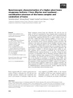
Multipath interference is the interference of a reflected signal with the direct path
transmitted signal or another reflected signal. An illustration of a communication channel
with multipath is shown in figure 1.1. The direct path, specular multipath component,
and diffuse multipath component are shown. The specular component is generally due to
reflection from a smooth or nearly smooth surface, while the diffuse component is due to
5
reflection from rough surfaces, or a group of small, randomly oriented surfaces. Plant foliage
is an example of a cause of diffuse multipath. This three part model (direct, specular, diffuse)
is applicable to most outdoor channels, since the direct path is usually visible, and a single
specular path is a good approximation even when there are multiple specular paths. The
corresponding simplified system impulse response for such a channel can be expressed as
h
(t
) =
δ(
t
) + Γ(
t)δ
(t
−
t
s
) +
ξ(
t
)δ(t
− t
d
) (1.1)
where the δ(
t
) term represents the direct path, t
s
is the specular path time delay, and t
d
is the diffuse path time delay. Γ(t) is the specular path scaling factor, and ξ(
t) is the
diffuse path scaling factor. Both Γ(t) and
ξ
(t
) include the complex reflection coefficient of
the surface, the antenna gain in the direction of the reflected path, and path attenuation.
The time dependence of Γ(t
) and
ξ
(
t
) is due to the fact that all of these properties, as
well as the location of the reflection point, change as either the transmitter or receiver
moves. The amplitude of the diffuse component, ξ(
t
) is considered to be random. When
t
s
= (2k + 1)
π, the direct and specular paths have opposite phases, resulting in destructive
interference. When Γ(
t
) is large, this interference can cause the amplitude of the received
signal to approach zero, or “fade out”. Multipath fading is a significant problem in both
outdoor and indoor communications, but the indoor problem is very different from typical
outdoor multipath environments.
In outdoor scenarios such as the one illustrated in figure 1.1, there is generally
one strong specular component. In urban environments, and more especially in indoor
environments, the number of significant specular multipaths increases dramatically. Since
most surfaces of reflection in a building are relatively smooth at the frequencies of interest,
and scattered media that produce diffuse reflection are minimal indoors, we will consider
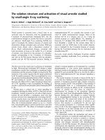
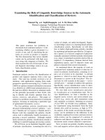
diffuse multipath to be negligible. Figure 1.2 shows an example of a transmitter and receiver
in neighboring rooms with some of the many possible propagation paths. Note that most
of the paths involve propagation through walls, including the direct path. As a result, the
direct path is attenuated, making the multipath components closer in amplitude and more
likely to cause destructive interference resulting in severe fades.
In this scenario, as is usually the case indoors, there are a very large number of
possible multipaths, but obviously after a certain number of reflections and transmissions
through walls, the signal is sufficiently attenuated to be considered negligible. For such a
6
Figure 1.1: Example of multipath in an outdoor channel
Transmitter
Receiver
Room A Room B
Hallway
Figure 1.2: Example of multipath in an indoor channel
7
scenario, the impulse response h(t
) can be expressed as an infinite sum:
h(t
) =
∞
k
=0
β
k
δ
(t − t
k
) (1.2)
where β
k
is the complex amplitude of the k
th arrival, and
t
k
is the associated time delay.
Note that
β
k
has no time dependence because there is no moving transmitter or receiver as
in figure 1.1.
As can be seen in figure 1.2, multipaths in an indoor environment can come
from a wide range of different angles. This can be an advantage because it allows for
interference rejection or coherent combining using various narrow beam antennas or spatial
array processing.
1.4.2 Beamforming
Conventional beamforming has been used as a means to reduce the effects of both
multipath and co-channel interference. Van Veen and Buckley [16] have written an excellent
tutorial, which expands on the basic ideas presented here, and reviews some of the algorithms
which are commonly used.
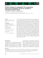
The basic principle of beamforming is that by adding the received signal from
several antennas with appropriate amplitude scaling and phase shifting, gains in signal power
and reduction in noise and interference power can be achieved. This results in higher signal
to noise ratios, and interferers can be nulled out. A diagram of a 4 element linear array is
shown in figure 1.3. The desired signal arrives from an angle
θ
. The distance
d
is the element
separation, usually about 1/2 wavelength. If some reference point in the wavefront reaches
the first antenna at time
t, the same wavefront reference point must travel a distance
d sin θ
to reach the next adjacent antenna. The propagation time is (d
sin θ)/c
, where c is the speed
of propagation. Therefore, to maximize the desired signal, the output should be:
y(
t
) =
x
0
(
t
) + e
j2
πd
sin θ/c
x
1
(t) + e
j4πd
sin
θ/c
x
2
(
t) + e
j6
πd sin θ/c
x
3
(t) (1.3)
This summing of the signal will maximize the received signal power, and at the same time
will likely combine the interfering signal so as to cause destructive interference. The received
signal to interference ratio after combining is thus increased dramatically.
Generalizing this for an array of
n elements, the output of an array y
(
t
) is given
8
Angle of
Desired
Signal
Interfering
Signal
0
x (t)
d
Incidence
1
Antennas
x (t)
3
x (t)
2
x (t)
θ
Figure 1.3: Illustration of a 4 element linear antenna array with two received signals
by:
y
(
t) =
n
k
=1
w
k
x
k
(
t
) (1.4)
where
w
k
is a “weight” which has a magnitude and phase component, and x
k
(t) is the
received signal at the
k
th element. This is often epressed in vector notation:
y(t
) = w
H
x(t) (1.5)
where
w is the vector of weights,
x
(t) is the vector of received signals at time t, and
w
H
represents the Hermetian transpose of w
.
Simple phase shifting as explained above gives a beam pattern with a main lobe
and side lobes whose magnitude and width are determined by the number of elements and
the overall dimensions of the array. In addition to phase shifting, the magnitudes of the
weights in w can also be changed with different windowing functions, for example, to alter
the characteristics of this lobe structure.
In addition to simple beamforming, a variety of other algorithms have been devel-
oped, including statistically optimum array processing algorithms which take advantage of
any prior knowledge about the signal and its correlation structure when selecting weighting
values for w
. These algorithms can effectively null out any undesired signals up to a limit,
which is generally determined by the size and number of elements in the array.
It has been shown that multipath interference is an important problem to be
addressed in the indoor environment. Beamforming and other multiple antenna schemes
9
have been presented as a method of combating this multipath interference. However, in order
to adequately compare the performance of the available algorithms, information is needed to
characterize the time delays and angles of arrival of the major multipath components in the
indoor channel. The angle of arrival has been largely ignored in the existing literature, but
angular multipath structure is the focus of this paper due to its importance in evaluating
performance of multiple antenna systems.
10
Chapter 2
EXISTING MODEL
Details of the the model proposed in [1] by Saleh and Valenzuela are presented
in this chapter. In comparison to other multipath models found in the literature, the Saleh-
Valenzuela model most closely reflects the characteristics of the data presented in this thesis,
and their method will be extended in Chapter 5 to include the angle of arrival.
2.1 The Saleh-Valenzuela Multipath Propagation Model
The model proposed by Saleh and Valenzuela is based on a clustering phenomenon
observed in their experimental data. In all of their observations, the arrivals came in one
or two large groups within a 200 ns observation window. It was observed that the second
clusters were attenuated in amplitude, and that rays, or arrivals within a single cluster,
also decayed with time. Their model proposes that both of these decaying patterns are
exponential with time, and are controlled by two time constants: Γ, the cluster arrival decay
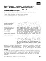
time constant, and γ, the ray arrival decay time constant. Figure 2.1 illustrates this, showing
the mean envelope of a three cluster channel.
The impulse response of the channel is given by:
h(t) =
∞
l
=0
∞
k
=0
β
kl
e
jφ
kl
δ(
t
−
T
l
− τ
kl
)
,
(2.1)
where the sum over
l represents the clusters, and the sum over
k represents the arrivals within
each cluster. The e
jφ
kl
term represents a statistically independent random phase associated
with each arrival, where φ
kl
is uniform on [0
,
2
π
).
The amplitude of each arrival is given by β
kl
, which is a Rayleigh distributed
random variable, whose mean square value is described by the double-exponential decay
illustrated in figure 2.1. Mathematically it is given by:
β
2
kl
=
β
2
(
T
l
, τ
kl
) (2.2)
=
β
2
(0
,
0)e
−
T
l
/
Γ
e
−
τ
kl
/γ
, (2.3)
where β
2
(0,
0) is the average power of the first arrival of the first cluster. This average power
is determined by the separation distance of transmitter and receiver.
11
time
overall
envelope
cluster
envelope
arrivals
amplitude
Figure 2.1: An illustration of exponential decay of mean cluster power and ray power within
clusters
The time of arrival is described by two Poisson processes which model the arrival
times of clusters and the arrival times of rays within clusters. The time of arrival of each
cluster is an exponentially distributed random variable conditioned on the time of arrival of
the previous cluster. The case is the same for each ray, or arrival within a cluster. Following
the terminology used by Saleh and Valenzuela, rays shall refer to arrivals within clusters, so
that the cluster arrival rate implies the parameter for the intercluster arrival times and the
ray arrival rate refers to the parameter for the intracluster arrival times. The distributions
of these arrival times are shown in equations 2.4 and 2.5:
p(
T
l
|T
l
−
1
) = Λ
e
−Λ(
T
l
−
T
l
−1
)
(2.4)
p(τ
kl
|
τ
(k
−
1)
l
) = λe
−
λ(τ
kl
−
τ
(
k−
1)
l
)
,
(2.5)
where Λ is the cluster arrival rate, and
λ is the ray arrival rate.
2.1.1 Model Parameters
In [1], the parameters Γ and
γ
were estimated by superimposing clusters with
normalized amplitudes and time delays and selecting a mean decay rate. The estimated
parameters from their data were Γ = 60 ns and
γ = 20 ns.
12
The Poisson cluster arrival rate parameter, Λ, was estimated by solving for Λ such
that the probabilities of the total number of clusters per random channel closely matched
the statistics of the observed data. This produced an estimate of 1/Λ ≈ 300 ns. The ray
arrival rate parameter was guessed at based on the average separation time between arrivals.
In this case the estimate was 1
/λ
≈
5 ns. Both of these estimates were very rough, but the
best guesses that could be derived from the data.
2.1.2 Angle of Arrival
In their data, Saleh and Valenzuela did not have any information on angle of
arrival, and therefore concluded that the angles of arrival were uniformly distributed over the
interval [0
,
2
π). For single antenna systems, time of arrival is generally sufficient information,
and angle of arrival not needed. However, as suggested in the introduction to this paper,
a need has arisen for a more accurate model as antenna array processors are considered for
indoor wireless applications. It will be shown later that the angle of arrival is not distributed
uniformly, but exhibits some of the same clustering characteristics seen in the time domain.
2.2 Other Models
Other models have been proposed since the Saleh-Valenzuela model. Ganesh and
Pahlavan [3] revised Turin’s model [2] for urban multipath propagation, which is based on
a modified Poisson process. In this process, the time axis is divided into bins, and the
probability of an arrival in a bin is partially dependent on whether there was an arrival in
the previous bin. Their model was used to simulate multipath indoor channels, and compare
delay spreads and received power levels. The modified Poisson model fit their experimental
data more closely than the clustered Poisson model. However, the modified Poisson model
does not include the clustering effects which are very pronounced in the data presented in
Chapter 6. Furthermore, the clustered Poisson process is simpler for simulation and analysis.
For these reasons, the extended model presented in this paper is based almost entirely on
the clustered Poisson model of Saleh and Valenzuela.
13
Chapter 3
DATA ACQUISITION SYSTEM
The time-of-arrival model proposed by Saleh and Valenzuela [1] was based on
data that specified arrivals by time only. A system could be built that measured received
power as a function of angle in a manner similar to the systems used for measuring antenna
beam patterns. This approach would provide an indication of the statistics of the angle of
arrival, but would yield no information regarding the correlation between time and angle of
arrival. In order to get an accurate picture of the time and angle of arrival and how they are
correlated, it is necessary to measure them both simultaneously. A system for doing this is
outlined in the following sections.
3.1 Testbed Configuration
One way to measure time and angle of arrival simultaneously, is to keep either
time or angle constant, while measuring the other, and repeat the procedure for a number
of different angles or times. In this case, the easiest scenario would be to look at a narrow
range of angles using an antenna with a narrow angular resolution, measure the time domain
impulse response of the channel, rotate the antenna, and repeat this until the antenna has
rotated an entire 360
◦
. The most obvious way to measure the impulse response of the channel
is to merely send a short pulse at the desired frequency and measure the received power as
a function of time. However, the problem with this approach is that there must be some
absolute time reference that is constant as the antenna is pointed in different directions.
In other words, there must be some synchronization of the entire system. The easiest way
to achieve this is to have some wired connection of known length between transmitter and
receiver. For indoor measurements the separation of transmitter and receiver is limited,
making this a practical option.
The system used for this thesis did not actually transmit a pulse, but simulated
the impulse response using a chirp. Using a chirp as opposed to a pulse achieves essentially
the same results, but there are some significant advantages, as well as some disadvantages
to the chirp signal. A chirp has a higher time-bandwidth product than a CW pulse of the
14
20 dB Signal Amplifier
PC
Monitor
Antenna Positioner
X Band Dish Antenna
30 dB Power Amplifier
HP Network Analyzer
Positioner Controller
120 foot coaxial cable
Monopole Antenna
(transmit)
Figure 3.1: The Data Acquisition System
same duration. In order to inject sufficient energy into the channel to achieve a high signal
to noise ratio, it is essential to have a transmitted signal that has much longer duration
than the desired time resolution. This is because practical transmitters have limited peak
power capability, and the 5 ns CW pulse required for direct time-of-arrival measurements
would simply be lost in the noise. A much longer chirp signal injects more power, but can
be designed with the same bandwidth as the 5 ns pulse. Since time resolution is inversely
proportional to bandwidth (when using the appropriate compression processing), the desired
time resolution is achieved with a longer (and thus higher energy) signal.
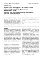
The system used to collect the data presented in this thesis is illustrated in figure
3.1. A network analyzer was used as a co-located transmitter and receiver, which sends
the transmitted signal through coaxial cable to the remote transmit antenna. The network
analyzer, designed to measure transmission and reflection coefficients at its two ports, is
configured to measure the transmission coefficient from the transmit antenna to the receive
antenna. The HP network analyzer which was used makes measurements of the channel
frequency response across a specified range of frequencies. It also has the capability of then
generating a time domain impulse response by calculating an inverse Fourier transform.
Because the timing is all done internally to the network analyzer, this method of generating
15
the impulse response provides a precise and consistent time reference when the antenna is
pointed at different angles.
3.2 Choice of Frequency
Recent allocations of bandwidth for purposes such as wireless indoor communi-
cations have been in the 900 MHz and 2.4 GHz ranges. At this time some commercially
available wireless products are available that use primarily the 900 MHz band, and in some
cases the 2.4 GHz band. Both of these bands, especially the 900 MHz band, have been the
subject of much research in indoor communications, but higher frequencies have had rela-
tively little attention. This is partly due to the fact that higher frequency bands have not
yet been allocated for indoor use. However, some recent researchers have begun to examine
the indoor applications of frequencies as high as 60 GHz [14].
Obviously, it would be desirable to use a frequency band already allocated for use
in indoor wireless applications, but the main factors influencing the choice of frequency in
this case were availability of hardware, portability of the system, and attenuation within the
system. The first two reasons both dictated a higher frequency. Narrow angular resolution
can be achieved with a smaller antenna at higher frequencies, allowing for more portabil-
ity. Furthermore, because of budget constraints, the system had to be built primarily with
existing hardware, and in this case, the most readily available equipment was designed for
X-Band (8-12 GHz). On the other hand, minimizing attenuation in the system dictated a
lower frequency because of the significant amount of coaxial cable used in the setup. Ul-
timately, 6.75 to 7.25 GHz was chosen because it was the lowest possible frequency range
that would work with the available dish antenna, which was fed by X-Band waveguide with
a cutoff frequency of 6.625 GHz.
The choice of a band centered at 7 GHz, although not currently in use for indoor
wireless communications, is justified for several reasons. A higher frequency reduces the
physical size of antennas, and for array applications, increases the number of antennas that
can be used in an array of given physical size. Higher frequency bands also generally are able
to support higher data rates because of higher available bandwidths. The main reason in
the past for keeping frequencies lower is reduced cost of hardware. However, it is reasonable
to assume that the cost of microwave equipment will decrease in the future, and building
systems which use high frequency bands will become more practical. Most importantly,
16
the data acquisition system described in this chapter can be easily converted for use in
other frequency bands by replacing the antennas with antennas suitable for the desired
band. Furthermore, since data of the type presented in this paper has not previously been
collected, these measurements taken at 7 GHz will provide a general idea of the multipath
properties of a wider band of microwave frequencies for indoor applications.
It is likely that channel parameters will differ for other frequency bands (like the
900 MHz and 2.4 GHz bands previously mentioned), but it is reasonable to assume that the
general multipath structure (i.e. clustering patterns, statistical distributions) will be similar.
For example, a channel from point A to point B such as the one shown in figure 1.2 will
have a certain impulse response with respect to time and angle at a given frequency. At
a lower frequency, the transmission and reflection characteristics of the walls and objects
will be different, likely altering the amplitude characteristics of the channel. However the
temporal and angular characteristics will remain unchanged. As will be discussed later, the
Saleh-Valenzuela model (generated from 1.5 GHz data) generated a reasonable fit to the 7
GHz data presented here. As a result, it can be assumed that the model presented here
should apply to lower frequency bands, although the parameters may differ somewhat.
3.3 Antenna Beam Pattern
The antenna used for the data acquisition system is a dish antenna with a diameter
of 60 cm. At a frequency of 7 GHz, the antenna has a 3 dB beam width of about 6
◦
(in both
the horizontal and vertical directions), and a null to null beam width of roughly 10
◦
. This
provides a very narrow angular resolution, but also presents another problem: it does not
allow arrivals with a vertical angular spread component.
Since the data being collected is with respect to horizontal angle only, it would
be desirable for the receiving antenna to have a wide beam width in the vertical direction,
so as to include all arrivals with any vertical component at a given horizontal angle. This
would allow for reflections off floor and ceiling to be included, as well as reflections off
walls and other objects. This would also be more representative of the beam pattern of an
array of vertical monopoles, a likely scenario for an indoor wireless communication system.
As illustrated in 3.2, the circular dish provides a relatively narrow beam pattern, causing
rejection of arrivals with any significant vertical component.
17
Antenna
Horizontal Arrival
Arrival with Vertical Component
Main Lobe of Beam
Figure 3.2: Antenna Vertical Component Rejection
angle (degrees)
delay (ns)
50 100 150 200 250 300 350
0
20
40
60
80
100
120
140
160
180
200
angle (degrees)
delay (ns)
50 100 150 200 250 300 350
0
20
40
60
80
100
120
140
160
180
200
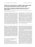
Figure 3.3: Data Collected with Original Antenna (left), and with Modified Antenna (right)
In order to compare the data collected with the dish antenna with data that in-
cluded more vertical components, the antenna was temporarily modified to widen its vertical
beam pattern. The antenna was masked with microwave absorbent material so that its ef-
fective physical shape was nearly rectangular. This resulted in a vertical 3 dB beam width of
about 30
◦
and null to null beam width of nearly 60
◦
. Using the modified antenna, a number
of the sets of data were repeated. A comparison of one of the data sets taken with both
antennas is shown in figure 3.3.
Comparing these two data sets, it is obvious that, while the relative amplitude of
some of the arrivals has changed, most of the main arrivals are present in both experiments,
and most importantly, the general structure of the clustering is unchanged. For purposes
of generating a statistical model, it appears that the statistics of the data have not been
appreciably affected. As a result, all of the data presented in this thesis was collected with
18
the original, unmodified antenna. Since masking the antenna caused gain losses of about
5 dB, using the unmodified antenna provides measurements with a better overall signal to
noise ratio (somewhat evident in figure 3.3).
19
Chapter 4
DATA PROCESSING AND ANALYSIS
4.1 Image Processing
The data collected by the testbed acquisition system consists of a series of time
domain impulse responses of the channel, measured for each test angle. When this data is
presented in matrix form, it represents a complete “image” of the channel. An example of
one data set is shown in image form in figure 4.1.
It is assumed that the indoor multipath channel is dominated by specular multi-
path. This assumption is supported by the data, in that multipath arrivals appear highly
localized in time and angle. The arrivals due to multipath can be assumed to be reflections
from walls, large furniture, and smaller objects which are highly conductive. Diffuse multi-
path in an outdoor environment is generally due to reflective surfaces that are not smooth,
such as foliage. Man-made objects, which comprise almost wholly the indoor environment,
tend to be smooth, especially at microwave frequencies. Diffuse multipath may exist indoors,
but it is assumed that its presence is negligible in the data presented here.
Because the multipath channel is assumed to be entirely specular, the image plots
such as the one shown in figure 4.1 can be modeled as a collection of point sources blurred
by a point spread function and corrupted by additive noise. This assumption reduces the
problem of identifying exact time and angle of arrival to a simplified deconvolution, which
would normally be very difficult in the diffuse source (or scattering) case.
The impulse response, or point spread function from an image processing point of
view, is shown in 4.2. This impulse response was generated by setting up the data acquisition
system in a line of sight environment with a high signal to noise ratio and no reflections in
the vicinity of the direct path. Along the angular axis, the main lobe and side lobes of the
antenna are visible, and along the time axis, the effects of windowing and pulse shaping in
time can be seen. In reality, there are side lobes in time, but the temporal side lobes are
smaller than the angular side lobes, and therefore not visible in the plot. Because the point
spread function is known, this deconvolution problem lends itself very well to the CLEAN
algorithm [17]. The CLEAN algorithm was originally used for processing of astronomical
20
angle (degrees)
delay (ns)
# 00021
50 100 150 200 250 300 350
0
20
40
60
80
100
120
140
160
180
200
Figure 4.1: Raw Data Set
images, which are also often modeled as groups of point sources convolved with a blurring
function. The algorithm is essentially a recursive subtraction of the point spread function
from the image, with the point spread function positioned to correspond with the maximum
value of the image. The highest peak is found, its amplitude, time, and angle are stored, and
a scaled copy of the impulse response is subtracted from the image. This process is repeated
on the residual image until a predetermined threshold (usually corresponding to the noise
level) is reached.
One problem faced in the processing of the data presented here is that since actual
arrivals do not happen at discrete intervals, it is nearly impossible to perfectly line up the
impulse response with a peak in the image. Even slight misalignment can lead to artifacts, or
points that were taken as arrivals where there obviously weren’t any. Furthermore, around
very strong arrivals, such as those in the middle of figure 4.1, the surrounding areas tended
to be significantly stronger than the noise floor. This combined with point spread function
(PSF) model error in the side lobes caused many points in those areas to be interpreted as
arrivals. Other sources of false detections may include volume reverberation or multiplicative
noise in the system.
To combat this problem, a scheme known as constant false alarm rate detection
21
0
100
200
300
400
0
5
10
15
0
0.002
0.004
0.006
0.008
0.01
0.012
0.014
0.016
angle (degrees)
delay (ns)
amplitude
Figure 4.2: Impulse response of the data acquisition system
was used. The noise floor threshold was adjusted at each point based on the average power
of the surrounding samples within a certain window. This greatly reduced the number of
false arrivals that were detected, but did not eliminate all. In this case the only other options
were to go to more complex algorithms that would still not be perfect, or to pick out all of
the major arrivals by manually looking at the image, which was not practical. The CLEAN
algorithm with constant false alarm level detection proved to be the simplest and overall
most reliable means of accurately identifying the time and angle of the major multipaths.
4.2 Cluster Finding
Once the arrivals were identified, an image plot of the processed data looks like
figure 4.3. This is the processed version of the raw data shown in figure 4.1. The next task is
to identify clustering. If the clustering effects found in [1] are present in the data, a channel
model should include clustering. In order to analyze the statistics of the clustering effects,
the clusters in each data set must be identified.
Early analysis of the data showed clustering effects in both time and angle. These
clusters were obvious to the observer in most cases. Some experimentation was done with
computer algorithms for automatic cluster identification, but eventually it was decided that
the overall amount of data was small enough that the clusters could just as easily and
22
angle (degrees)
delay (ns)
# 00021
50 100 150 200 250 300 350
0
20
40
60
80
100
120
140
160
180
200
Figure 4.3: The data set shown in figure 4.1 after processing
accurately be picked by hand. This was done by a computer program that showed the image
graphically and allowed the user to identify clusters using graphical input. With the times,
angles, and amplitudes of all major arrivals identified, as well as their clustering patterns,
the data could be used to analyze the statistics and arrive at a model.
23
Chapter 5
A COMBINED TEMPORAL/SPATIAL STATISTICAL MODEL
FOR INDOOR MULTIPATH PROPAGATION
5.1 Time of Arrival
In this chapter we propose a statistical model for the indoor multipath channel
that includes a modified version of the time-of- arrival model outlined in Chapter 2, and
incorporates an angle-of-arrival model.
The time and amplitude of arrival portion of the combined model is represented
by
h(t
) in equation (2.1), where, as before,
β
2
kl
is the mean square value of the
k
th arrival
of the
l
th cluster. This mean square value is described by the exponential decay given in
equation (2.3) and illustrated in figure 2.1.
As before, the ray arrival time within a cluster is given by the Poisson distribution
of equation (2.5), and the first arrival of each cluster is given by T
l
, described by the Poisson
distribution of (2.4). The inter-ray arrival times, τ
kl
, are dependent on the time of the
first arrival in the cluster
T
l
. In the Saleh-Valenzuela model, the first cluster time
T
1
was
dependent on T
0
which was assumed to be zero. With the estimated parameter in [1] of
1/
Λ ≈
300 ns, the first arrival time will typically be in the range of 200 to 300 ns, which
is a reasonable figure. However, a problem with this was found when the Λ parameter in
the new data was discovered to be very low, for reasons which will be discussed later. This
makes any long delays which would occur at larger separation distances between transmitter
and receiver highly improbable. To remedy this problem, it is proposed that
T
0
be the line
of sight propagation time:
T
0
=
r
c
,
(5.1)
where
c is the speed of light, and
r is the separation distance. This allows for the time of
the first arrival to be more directly dependent on the separation distance.
24