Fabrication of superhydrophobic surface on filter paper by a facile coating method and application in environmental treatment
Bạn đang xem bản rút gọn của tài liệu. Xem và tải ngay bản đầy đủ của tài liệu tại đây (1.71 MB, 62 trang )
VIETNAM NATIONAL UNIVERSITY, HA NOI
VIETNAM JAPAN UNIVERSITY
DINH DAM KHANH
FABRICATION OF SUPERHYDROPHOBIC
SURFACE ON FILTER PAPER BY A
FACILE COATING METHOD AND
APPLICATION IN ENVIRONMENTAL
TREATMENT
MASTER’S THESIS
VIETNAM NATIONAL UNIVERSITY, HA NOI
VIETNAM JAPAN UNIVERSITY
DINH DAM KHANH
FABRICATION OF SUPERHYDROPHOBIC
SURFACE ON FILTER PAPER BY A
FACILE COATING METHOD AND
APPLICATION IN ENVIRONMENTAL
TREATMENT
MAJOR: ENVIRONMENTAL ENGINEERING
CODE: 8520320.01
RESEARCH SUPERVISORS:
Dr. TRAN THI VIET HA
Dr. NGUYEN MINH VIET
Hanoi, 2021
ACKNOWLEDGEMENTS
For the accomplishment of this master thesis, I have received plenty of
invaluable support. First of all, I would like to express my deep gratitude and sincere
thanks to Dr. Tran Thi Viet Ha, my principal supervisor, for giving me an opportunity
to do this research and extend my knowledge. I am extremely grateful to her for
providing such an indispensable support and guidance throughout my thesis procedure.
Secondly, I would like to thank Dr. Nguyen Minh Viet, my co-supervisor, for
his instruction and enthusiasm to help me complete my master thesis successfully. He
helped me gain lots of experiences in working with analysis equipment.
Last but not least, I am deeply grateful to my parents, my lecturers in Vietnam
Japan University and my classmates for their support and encouragement during all the
time I have been studying here and carrying out my thesis, which motivates me a lot to
successfully complete my master course and master thesis.
TABLE OF CONTENTS
CHAPTER 1: INTRODUCTION........................................................................................ 1
CHAPTER 2: LITERATURE REVIEW............................................................................. 4
2.1. Wettability and water contact angle ........................................................................... 4
2.2. Fabrication methods of superhydrophobic surface .................................................... 6
2.2.1. Chemical etching method .................................................................................... 7
2.2.2. Sol-gel method ..................................................................................................... 8
2.2.3. Dip-coating method ............................................................................................. 9
2.2.4. Electrochemical deposition method ................................................................... 10
2.2.5. Plasma-etching method ...................................................................................... 11
2.2.6. Hydrothermal method ........................................................................................ 12
2.2.7. Self-assembly method ........................................................................................ 13
2.3. Techniques for superhydrophobic surface analysis ................................................. 13
2.3.1. Scanning electron microscope (SEM) ............................................................... 13
2.3.2. Energy-dispersive X-ray spectroscopy (EDX or EDS) ..................................... 15
2.3.3. Fourier-transform infrared spectroscopy (FTIR) ............................................... 17
2.3.4. X-Ray Diffraction (XRD) .................................................................................. 18
2.3.5. Water contact angle measurement ..................................................................... 20
2.4. Previous studies about application of superhydrophobic material in oil-water
separation ........................................................................................................................ 21
CHAPTER 3: MATERIALS AND METHODOLOGIES ................................................ 24
3.1. Objectives and contents of the study........................................................................ 24
3.1.1. Objectives of the study ...................................................................................... 24
3.1.2. Contents of the study ......................................................................................... 24
3.2. Materials ................................................................................................................... 24
3.3. Investigation of fabrication parameters.................................................................... 24
3.3.1. Investigation of ZnO coating procedure ............................................................ 25
3.3.2. Investigation of ZnO coating solvent ................................................................ 26
3.3.3. Comparison between one-step coating and two-step coating............................ 26
3.3.4. Investigation of ZnO coating pH ....................................................................... 27
3.3.5. Investigation of ZnO coating cycle number ...................................................... 27
3.3.6. Investigation of stearic acid coating cycle number ........................................... 27
3.4. Fabrication of superhydrophobic surface on filter paper ......................................... 28
3.5. Characterization of fabricated filter paper surface................................................... 28
3.6. Applicability of fabricated filter paper in environmental treatment ........................ 29
3.7. Durability and reusability of fabricated filter paper ................................................ 30
3.7.1. Durability of fabricated filter paper ................................................................... 30
3.7.2. Reusability of fabricated filter paper ................................................................. 31
CHAPTER 4: RESULTS AND DISCUSSIONS .............................................................. 32
4.1. Investigation of fabrication parameters.................................................................... 32
4.1.1. Investigation of fabrication procedure ............................................................... 32
4.1.2. Investigation of fabrication solvent ................................................................... 32
4.1.3. Comparison between one-step coating and two-step coating............................ 33
4.1.4. Investigation of coating pH ............................................................................... 33
4.1.5. Investigation of ZnO coating cycle number ...................................................... 34
4.1.6. Investigation of stearic acid coating cycle number ........................................... 35
4.2. Fabrication of superhydrophobic surface on filter paper ......................................... 36
4.3. Characterization of fabricated filter paper surface................................................... 36
4.3.1. Scanning electron microscope (SEM) analysis ................................................. 36
4.3.2. Energy-dispersive X-ray spectroscopy (EDX) analysis .................................... 37
4.3.3. X-Ray Diffraction (XRD) analysis .................................................................... 38
4.3.4. Fourier-transform infrared spectroscopy (FTIR) analysis ................................. 39
4.3.5. Proposal of superhydrophobic coating formation mechanism .......................... 40
4.3.6. Water contact angle (WCA) and water shedding angle (WSA) ........................ 41
4.4. Applicability of fabricated filter paper in environmental treatment ........................ 42
4.5. Durability and reusability of fabricated filter paper ................................................ 43
4.5.1. Durability of fabricated filter paper ................................................................... 43
4.5.2. Reusability of fabricated filter paper ................................................................. 46
CHAPTER 5: CONCLUSION .......................................................................................... 48
LIST OF TABLES
Table 4.1. Recovery rates in oil-water separation experiments ......................................... 43
Table 4.2. Recovery rates in oil-water separation after durability tests ............................ 46
Table 4.3. Recovery rates in reusability tests .................................................................... 47
i
LIST OF FIGURES
Figure 1.1. Superhydrophobic surfaces in nature ................................................................ 1
Figure 2.1. Hydrophilic and hydrophobic surface ............................................................... 4
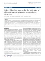
Figure 2.2. Schematic of (a) Young’s equation, (b) Wenzel’s model and (c) CassieBaxter’s model (Edalatpour et al., 2018).............................................................................. 6
Figure 2.3. Back-scattered electron image showing the difference in contrast due to
the atomic number: (A) observed material and (B) image of back-scattered electrons
(Kim et al., 2010). ............................................................................................................... 14
Figure 2.4. Schematic representation of the types of X-ray spectrum emitted upon
bombardment of fast electron (Reichelt, 2007) .................................................................. 16
Figure 2.5. Basic component in Fourier transform infrared spectrometer (Mohamed et
al., 2017) ............................................................................................................................. 17
Figure 2.6. Basic features of a typical XRD experiment (Toney, 1992) ........................... 19
Figure 2.7. Contact angle goniometer system ................................................................... 21
Figure 3.1. Coating steps in fabrication of superhydrophobic surface .............................. 25
Figure 3.2. Water shedding angle determination experiment............................................ 29
Figure 3.3. Vacuum filter holder ....................................................................................... 30
Figure 4.1. The filter papers after coated using different solvents .................................... 33
Figure 4.2. The WCAs of paper with (a) ZnO coating, (b) stearic acid coating and (c)
ZnO-stearic acid coating..................................................................................................... 33
Figure 4.3. The WCAs of filter paper with (a) 2 coating cycles and (b) 4 coating
cycles of ZnO...................................................................................................................... 34
Figure 4.4. WCA measurement of filter paper with (a) 1 coating cycle and (b) 2
coating cycles of stearic acid .............................................................................................. 35
Figure 4.5. SEM pictures of (a) bare filter paper, (b) filter paper with ZnO coating and
(c) filter paper with ZnO and stearic acid coating .............................................................. 37
Figure 4.6. EDX analysis of (a) bare filter paper, (b) filter paper with ZnO coating and
(c) filter paper with ZnO and stearic acid coating .............................................................. 38
Figure 4.7. XRD analysis of bare and coated papers ........................................................ 39
Figure 4.8. FTIR analysis of bare and coated papers ........................................................ 40
Figure 4.9. Formula structure of (a) cellulose and (b) stearic acid.................................... 40
Figure 4.10. Schematic illustration of the superhydrophobic coating ............................... 41
Figure 4.11. Water shape in WCA measurement .............................................................. 41
Figure 4.12. The mixture of oil and water (a) before filtration and (b) after filtration ..... 42
Figure 4.13. Water drop shape on fabricated paper (a) in the beginning and (b) after 4
months ................................................................................................................................ 43
Figure 4.14. The tape after adhesive tape test ................................................................... 44
Figure 4.15. Water drop shape on fabricated paper (a) in the beginning and (b) after
adhesive tape test ................................................................................................................ 44
ii
Figure 4.16. Water drop shape on fabricated paper (a) in the beginning and after
immersion in solution with (b) pH = 1, (c) pH = 7 and (d) pH = 13 .................................. 45
Figure 4.17. Recovery rates in oil-water separation after durability tests ......................... 46
Figure 4.18. Recovery rates in reusability tests ................................................................. 47
iii
LIST OF ABBREVIATIONS
EDX: Energy-dispersive X-ray spectroscopy
FTIR: Fourier-transform infrared spectroscopy
SEM: Scanning electron microscope
WCA: Water contact angle
WSA: Water shedding angle
XRD: X-Ray Diffraction
iv
CHAPTER 1: INTRODUCTION
Nature is the inspiration to many scientists and engineers to create remarkable
inventions for human life. There are numerous materials, structures and systems in the
natural world which human observe and imitate to design and invent new products.
This creative process is known as biomimicry. One notable example for biomimicry is
the superhydrophobic surface. In nature, we can find many superhydrophobic surfaces
of plants and animals, such as lotus leaves and butterfly wings (Figure 1.1), with
waterproof, self-cleaning and anti-adhesion properties. These properties are studied
and applied in many fields of life such as making anti-fogging materials (Das et al.,
2018), anti-freezing materials (Chevallier et al., 2011), self-cleaning materials
(Satapathy et al., 2018), or environmental treatment (Sriram et al., 2020).
Figure 1.1. Superhydrophobic surfaces in nature
Recently, superhydrophobic surfaces with high applicability have received more
attention from researchers. Various methods have been developed to prepare
superhydrophobic surfaces, for example, sol-gel method (Fan et al., 2012), selfassembly (Song et al., 2010), chemical etching (Qian & Shen, 2005), plasma etching
(Ji et al., 2009), vapor deposition (Rezaei et al., 2014) and so on. Moreover, there are
also many studies on fabricating superhydrophobic surfaces on different substrates
such as fabric (Ge et al., 2020), glass (Shi et al., 2005), silicon (Song et al., 2010) or
metal surface (Fan et al., 2012; Movahedi & Norouzbeigi, 2019), etc. with diverse
applications. Based on the basis of the substrate, the appropriate fabricating method
will be chosen and developed differently to successfully prepare the superhydrophobic
surface.
1
In environmental aspect, the most important application of superhydrophobic surfaces
is oil-water separation. Currently, in the world of industrialization and modernization,
oil production and oil transportation have been developed rapidly, which increased the
risk of oil spill cases in the ocean. As a result, oil pollution from oil spill accidents
becomes a big problem to the environment, which can cause serious impacts on marine
life, human health and the ecology. One of the most infamous cases is Arctic Oil Spill
in 2020, in which about 21000 tons of oil poured into the surrounding ground and
waterways near the city of Norilsk after a diesel oil tank collapsed, causing critical
damages to the ecology in this area. In order to solve this problem, many methods
have been applied including combustion, chemical treatment, bioremediation, etc.
However, these methods can cause the secondary pollution after being applied. For
instance, combustion method can help to remove the oil from the water but it also
causes air pollution because of producing the large amount of CO2, SO2 after the
procedure. Different from those, utilization of superhydrophobic material is a new
method that is considered as an effective solution for oil spills without causing any
secondary pollution.
In this study, filter paper - one of the most commonly used materials in both daily life
and research laboratory – is chosen to be used as the substrate. The filter paper is
mainly composed of cellulose, a polysaccharide with many hydroxyl groups, a
hydrophilic functional group, making the filter paper extremely easy to absorb water.
By changing the surface wetting property from hydrophilic to hydrophobic, the
application of the filter paper will be expanded, and one of them is separating oil and
water in a mixture of these solutions. Compared to other substrates reported in
previous studies such as fabric (Ge et al., 2020), silicon (Song et al., 2010) or metal
(Qian & Shen, 2005), the filter paper possesses many advantages such as high
flexibility, biodegradability and low cost. Moreover, the number of published studies
about applying superhydrophobic filter paper in environmental treatment is also quite
limited, despite the fact that it is considered as a potential method for oil-pollution
treatment.
2
Therefore, this study is going to focus on developing the anti-wetting surface on filter
paper substrate, and then applying it in environmental treatment, opening up different
new research directions in the future.
3
CHAPTER 2: LITERATURE REVIEW
2.1. Wettability and water contact angle
Static water contact angle (WCA) is the parameter used for quantifying the wettability
of a surface. The contact angle is defined as the angle created by the intersection of the
liquid-solid interface and the liquid-vapor interface (geometrically obtained by making
a tangent line from the contact point along the liquid-vapor interface in the droplet
profile) (Sethi et al., 2019). In 1805, Young proposed the first fundamental equation
that quantified the hydrophobicity/hydrophilicity of a surface based on a static contact
angle:
(1)
in which,
is the static water contact angle, γSV, γSL and γLV are the interfacial tensions
of the solid-vapor, solid-liquid and the liquid-vapor interface, respectively. By
proposing this relationship equation, he is widely regarded as the pioneer of scientific
research on wettability and water contact angle (Young, 1805).
A surface is considered as hydrophilic when WCA < 90° (γ SV > γSL), while it is
considered hydrophobic when WCA ≥ 90° (γSV ≤ γSL) (Sethi et al., 2019). The pictures
of hydrophilic and hydrophobic surface are shown in Figure 2.1.
Figure 2.1. Hydrophilic and hydrophobic surface
However, Young’s equation is only applied for perfectly smooth and chemically
homogeneous solid surface. Wettability of rough or chemically heterogeneous surfaces,
which are more practical surfaces, is much more complicated. Two noticeable models
4
describing the influence of surface roughness to water contact angle are Wenzel model
and Cassie & Baxter model (Subhash Latthe et al., 2012).
In 1936, Wenzel developed a model in which the water drop can penetrate into the
grooves on a rough surface. During his experiments, he found that roughness makes a
hydrophilic surface more hydrophilic, and makes a hydrophobic surface more
hydrophobic. He proposed an equation showing the relation of the water contact angle
on smooth surface and rough surface as following:
(2)
in which,
is the water contact angle on a rough surface,
a similar smooth surface, and
is water contact angle on
is the surface roughness factor, defined as the ratio of
actual area of the solid surface to the projected area ( = 1 for a perfectly smooth
surface, and
> 1 for a rough one). The Wenzel equation indicates that the
hydrophilicity is enhanced by roughness when
increased by roughness when
is < 90°, while the hydrophobicity is
is > 90° (Wenzel, 1936).
After the introduction of Wenzel’s model, in 1944, Cassie and Baxter reported that
Wenzel’s equation was unable to accurately predict the water contact angle of droplets
on rough surfaces with air pockets trapped in the rough grooves. Hence, they proposed
another model in which wetting state is considered that the grooves under the droplet
are filled with vapor instead of liquid (Cassie & Baxter, 1944). They modified the
Wenzel’s equation and introduce another one that can predict the contact angle on
these cases as below:
(3)
in which,
and
represents the contact angle of the smooth solid surface,
represents the
contact angle for air.
5
Figure 2.2. Schematic of (a) Young’s equation, (b) Wenzel’s model and (c) CassieBaxter’s model (Edalatpour et al., 2018)
Superhydrophobic surface can be defined as the surface with high water contact angle
(≥150°), low sliding angle/shedding angle (≤ 10°), anti-sticking, anti-contamination,
and self-cleaning effect (Kumar & Nanda, 2019). In nature, many different surfaces
such as lotus leaves, rice leaves, butterfly wings, cicada wings and rose petals perform
superb hydrophobicity or superhydrophobicity. The properties of superhydrophobic
surfaces are potential for many applications in real life like production of anti-fogging
materials, anti-freezing materials and self-cleaning materials.
2.2. Fabrication methods of superhydrophobic surface
Study on superhydrophobic surface fabrication was first introduced in 1996 by the
research group of Satoshi Shibuishi in Japan (Shibuichi et al., 1996). Since then, the
superhydrophobic surface with high applicability has drawn numerous attentions from
scientists. There are two factors affecting the wettability of a surface: surface
chemistry and surface roughness (Nguyen-Tri et al., 2019). Based on this principle,
various methods have been researched and developed to fabricate superhydrophobic
surfaces on different materials.
6
2.2.1. Chemical etching method
Chemical etching is a wet method in which the surface molecules are made to react
with highly acidic or basic solutions to produce roughness. Although it only requires
simple equipment, simple chemical with low cost, it is a fast process and provide high
etching rate and high selectivity. However, it still has some disadvantages. This
method requires big amount of etching chemicals and can cause contamination to the
substrates. It is also difficult to control the etching rate of the process.
Many researches using this method to fabricate superhydrophobic surface have been
published. For example, in a study conducted by Qian and Shen (2005), aluminum,
copper, and zinc surface were chemically etched with Beck’s dislocation etchant,
Livingston’s dislocation etchant and HCl solution, respectively. Then, the etched
surfaces were immersed in tridecafluoroctyltriethoxysilane solution to change the
surface composition. After the procedure, static water contact angle of 156°, 153°, and
155° were achieved for aluminum, copper, and zinc surface.
Xie and Li (2011) also applied this method to fabricate superhydrophobic aluminum
plate with boiling aqueous solution of NaOH as etching solution to create roughness
and lauric acid as chemical modifying solution after the etching step. The fabricated
aluminum surface showed good hydrophobicity with a water contact angle greater than
150°.
In Varshney et al.’s study (2017), superhydrophobic steel mesh was prepared for the
purpose of oil-water separation. The process also included two steps: etching step
using solution of hydrochloric acid and nitric acid and surface chemistry altering step
using lauric acid. The produced mesh was then proved to be mechanically, chemically,
and thermally stable with static water contact angle of 171 ± 4.5° and sliding angle of
4 ± 0.5°.
Lee et al. (2011) introduced a method to achieve superhydrophobic silicon surface
with water contact angle of nearly 180°. The silicon wafer roughness was increase by
immersing in Cu plating solution, then in solution of HF and H2O2 to form micro and
nanostructure. Next, the silicon surface was treated with Teflon to successfully obtain
7
an excellent superhydrophobic surface that can be applied in self-cleaning and
microfluidic transportation.
2.2.2. Sol-gel method
Sol-gel technique is considered as the most common method to fabricate
superhydrophobic material, which is can be applied for a variety of solid substrate
surface. In this method, colloidal particles with different sizes (from 1 to 100nm) are
dispersed in gels having an inter-connected rigid network with micro/nano pores and
polymeric chains with the length great than 1μm. Here, the monomer converses into
colloidal solution (sol) that performs as an initiator for integrated network (gel) for
polymers or particles.
There are numerous studies about application of this method in superhydrophobic
material having been introduced. By using sol-gel method, Fan et al. (2012) achieved
superhydrophobic surface on copper wafer with water contact angle of 155.4°. The
copper surface was first etched in acid solution to increase roughness, followed by
coating with sol-gel solution containing vinyl trimethoxylsilane, ethanol, water, and
ammonia. After the procedure, the fabricated sample can remain stable in 3.5% NaCl
solution, which means it can be prospective in anticorrosion and self-cleaning
applications.
Wang et al. (2008) also prepared superhydrophobic surfaces on various substrates
including textile fabrics (polyester, wool and cotton), filter papers, glass slides,
electrospun nanofibre mats and silicon wafers with water contact angles over 170° and
sliding angles below 7° using this method. The sol solution with silica nanoparticles
was prepared by co-hydrolysis and condensation of tetraethyl orthosilicate (TEOS) and
tridecafluorooctyl triethoxysilane (FAS) in NH3–H2O–ethanol solution. This sol
solution was then coated onto different substrate surfaces to form a transparent film.
In a study conducted by Satapathy et al. (2018), a superhydrophobic glass surface
preparation method was presented. The glass was dipped in solution of sol-gel SiO2
nanoparticles embedded in linear low-density polyethylene (LLDPE) polymer matrix.
The porosity of SiO2 nanoparticles embedded in LLDPE was also changed variously
using ethanol as non-solvent. Finally, the prepared SiO2 nanoparticles embedded in
8
LLDPE matrix possessed a water contact angle of 170° and sliding angle of 3.8°,
which is extremely remarkable. In addition, the sample was also thermally,
mechanically and chemically stable with good self-cleaning performance.
2.2.3. Dip-coating method
Dip coating method is a technique in which the substrate is immersed into a solution of
the component to be deposited on the substrate surface. After the required time, the
sample is withdrawn from the solution, creating the film deposited on the substrate.
The solvent utilized is then evaporated, resulting in a coating layer on the sample
surface. This technique has several advantages, including simultaneous coating of the
upper and lower sides of the substrate, no waste of material, applicable to various
types of materials, high output, uniform, stable and well durable coating. However, in
this method, all components must be submersible to be able to make the coating layer.
Mahadik et al. (2013) proposed a simple and low-cost dip coating method to fabricate
superhydrophobic surface by using organic and inorganic silica precursor
methyltrimethoxysilane (MTMS) to produce superhydrophobic silica coatings on
quartz substrate. After coating step, the recorded water contact angle and water sliding
angle were 168 ± 2° and 3 ± 1°, respectively. This fabricated surface had notable
properties of superhydrophobicity and superoleophilicity along with the high
durability and optical transparency.
In Sun et al.’s study (2014), superhydrophobic surfaces on zinc substrate was
fabricated based on the electrochemical processing of Zn under an applied electric
field. This research applied an electrochemical procedure using an electrolyte mixture
consisting of NaNO3 and NaCl to enhance surface roughness, followed by dip-coating
process with fluoroalkylsilane-ethanol solution to modify surface chemistry of the
sample. After two-step process, the zinc surface had the maximum water contact angle
of 165.3° and the tilting angle of 2°.
Sriram et al. (2020) developed a fabrication method of superhydrophobic filter paper
using combination of sol-gel and dip-coating method. First, the sol-gel solution was
prepared by adding poly (methyl methacrylate-co-ethyl acrylate) polymer silicon
dioxide nanoparticles to toluen under stirring, followed by adding PFOTS silane for
9
better dispersion of nanoparticles. Then, the filter paper was coated with the solution
above via dip-coating method at ambient condition. The achieved water contact angle
of filter paper surface was greater than 175°, and the sliding angle was 3.8°.
2.2.4. Electrochemical deposition method
Electrochemical deposition is a technique which induces chemical reactions in an
aqueous electrolyte solution with the presence of applied voltage. The advantages of
this method are able to get material into arbitrary three-dimensional (3D) geometry
and suitable for applying to soft substrates since it is a low-energy process. In addition,
it can be carried out in room temperature using water-based electrolytes. The main
disadvantage of electrochemical deposition is that it is only appropriate for selected
size and weak in terms of structure strength.
Huang et al. (2010) presented a one-step electrochemical deposition process to
fabricate superhydrophobic surface on copper substrate. In their work, the process was
performed by applying a direct voltage (DC) between two copper plates immersed in
an ethanol-stearic acid solution. The reaction between copper and stearic acid solution
took place, causing the transformation of the anodic copper electrode surface to
superhydrophobicity. The surface of the anodic copper was observed to be covered
with flower-like copper stearate films via SEM images. The water contact angle the
copper surface was 153° ± 2° with the rolling off properties of the droplets.
In He and Wang’s study (2011), this method was utilized to prepare superhydrophobic
zinc foil, in which ZnO nanorods were grown on the surface of ZnO film (oxidized
zinc foil at 310°C) by electrochemical deposition, then spin-coated with perfluoroalkyl
methacrylic copolymer to achieve superhydrophobic state. After the procedure, the
recorded water contact angle was 167°, showing great potential in various applications
such as anti-contamination, anti-fouling and self-cleaning.
Wang et al. (2011) proposed a three-step method for fabrication of biomimetic
hierarchical structure on aluminum surface. First, anodized porous alumina (APA) film
was prepared to form specimens. These specimens were then electrodeposited by
nickel and copper to form nanometer pillars. Finally, the roughed surface was then
chemically modified with fluoroalkylsilane to achieve water contact angle of 152°, and
10
hysteresis angle of 6° for nickel deposited and water contact angle 157° and hysteresis
angle of 3° for copper deposited one.
2.2.5. Plasma-etching method
Plasma-etching is a method using a high stream speed of glow discharge (plasma) of
an appropriate gas mixture to shoot at a sample. During this process, the plasma
generates volatile etch products from the chemical reactions between the elements of
the etched sample and the reactive species, which then modify the surface of the
sample. Plasma treatment could create micro or nanostructures. The strong points of
this technique are capability of automation, low material consumption, environmentalfriendliness and low damage to photoresist. The weak points are high capital
investment, difficulty in controlling parameters (surface geometry, types of gases, flow
rates, system conductance, patterning, etc.), surface damage caused by plasma
radiation and toxicity of gases.
Gao et al. (2012) carried out two-step plasma-etching method to prepare
superhydrophobic zinc surface with the water contact angle of 158°and sliding angle
below 5°. The surface was etched with glow discharge electrolysis plasma (GDEP) to
increase surface roughness and chemically transformed with stearic acid. Eventually,
the prepared zinc surface showed great hydrophobicity and durability to different pH
and long-term environmental exposure.
Ji et al. (2009) developed a simple method for fabrication of superhydrophobic coating
on glass involving in-line atmospheric RF glow discharge plasma with a non-polar
aromatic
toluene
and
HMDSO
mixture.
The
fabircated
glass
exhibited
superhydrophobicity property with the water contact angle of about 150°. The plasma
system used did not require any vacuum instruments, and was suitable to operate in an
in-line mode, which means it can easily be scaled up for treatment of larger substrates
and for continuous processing.
In a study conducted by Psarski et al. (2014), nanostructured epoxy/γ-Al2O3
nanoparticle composite was prepared using this method. First, the microstructures
were developed on aluminum surface by laser. After that, the derived composite was
etched with plasma source in order to create nano-roughness. The etched sample was
11
then modified with 1H,1H,2H,2H perfluorotetradecyltriethoxysilane using dip-coating
method to achieve superhydrophobic state with a contact angle of 160°and a sliding
angle of 8°.
2.2.6. Hydrothermal method
Hydrothermal method is a technique producing crystalline substances in hot aqueous
solution at high vapor pressure. This method is usually used for creating roughness on
the sample surface by using high temperature and high pressure. In the procedure,
crystals are grown in an autoclave with the substrate and supplied water. This method
is able to synthesize large crystals with high quality and applicable in industrial scale
due to its simple approach. Nevertheless, the crystal growth cannot be monitored or
controlled during the process, and the cost of apparatus for this method is also high.
Shi et al. (2005) proposed a hydrothermal method for preparation of superhydrophobic
glass. The glass sample was hydrothermally treated with solution containing
Al(NO3)3.9H2O, NaOH and colloidal silica to create rose-like microstructures
depositing on surface sample to enhance surface roughness, followed by chemically
modified with octyltrimethoxysilane to achieve superhydrophobicity state. After the
process, the prepared sample achieved water contact angle of 154° and sliding angle of
lower than 3°.
Wu et al. (2010) proposed an alkaline hydrothermal method to fabricate
superhydrophobic surface with ZnO micro and nanostructure. The treated sample after
hydrothermal step was observed to have rose-like structures on the surface, which
were responsible for roughness enhancement. After next step, spin-coating with Teflon,
the sample obtained superhydrophobicity with contact angle of 168° and high stability
(no change after being immersed in water for 15 days). Overall, the proposed method
is simple to control, cost-effective, and potential to apply in many fields.
In a research conducted by Shen et al. (2014), different nanostructures were developed
by using three different techniques, one of which was hydrothermal technique, on
microstructured Ti6Al4V alloy surface. Nanowire, nanotube and nanomesh structures
were respectively created by hydrothermal method, anodic oxidation and by two-step
chemical reaction. The surface was then chemically modified with FAS-17 to achieve
12
the water contact angle of 161° and tilting angle of 6°, which was remarkable
superhydrophobicity.
2.2.7. Self-assembly method
In self-assembly method, a disordered system of preexisting components assembles in
an organized way or in a sequence due to interactions of local non-covalent molecules.
It can form complex structures with minimum interference. This method has some
advantages, including the ability to grow the layer at low temperature without
requirement of expensive equipment and complex processes. Thus, this type of surface
treatment method can be applied widely. However, this process consumes great
amount of time and has sophisticated mechanism.
Yin et al. (2011) used chemical etching and self-assembly method to prepare
superhydrophobic copper. The copper was first etched with sodium hydroxide and
potassium persulfate solution to create flower-like structures and nanoneedles of
Cu(OH)2 on the sample surface. Then, the roughed sample was immersed in
dodecanoic acid, which forms self-assembled layer on the surface. Eventually, the
prepared surface possessed good superhydrophobic state with water contact angle of
153°.
In a study conducted by Song et al. (2010), a method for fabricating superhydrophobic
surface silicon was introduced. The micro/nano textures were generated on silicon
substrate surface by the aluminum-induced crystallization of amorphous silicon
technique. The next step was applying an octadecyltrichlorosilane self-assembled
monolayer on silicon textured surface. The fabricated surfaces achieved a water
contact angle of 155° and a sliding angle of less than 1°.
2.3. Techniques for superhydrophobic surface analysis
2.3.1. Scanning electron microscope (SEM)
Scanning electron microscope is a type of electron microscope that produces images of
a sample by scanning the surface with an accelerated beam of electrons. The highresolution scanning electron microscope (SEM) is brilliant for characterization of
micro and nano-particle size samples because of simple sample preparation and quick
image acquisition of the technique (Vladár & Hodoroaba, 2020).
13
The signals are used by SEM system to create an image result from interactions of the
electron beam with atoms at different depths within the sample. Various types of
signals are utilized including secondary electrons (SE), back-scattered electrons (BSE),
characteristic X-rays, absorbed current (specimen current) and transmitted electrons.
Secondary electron detectors are standard in all SEMs, but it is rare for a single
apparatus to have detectors with all other signals.
Secondary electrons have quite low energy on the order of 50 eV, which limits their
free path in solid matter. Therefore, the SEs can only escape from the top few
nanometers of the sample surface. Signals from the secondary electrons have the
tendency to be localized at the impact point of the primary electron beam, so an image
of the sample surface can be obtained with a resolution less than 1 nm.
Back-scattered electrons (BSE) are beam electrons reflected off the sample by elastic
scattering. As they have much higher energy than SE, they appear from deeper
locations in the specimen, thus, the resolution of the BSE image is lower than the SE
image. Nevertheless, BSE is often used in analytical SEM, along with spectra
generated from characteristic X-rays, since the BSE signal intensity is closely related
to the atomic number (Z). BSE image can present information about the distribution
(not identification) of different elements in the sample.
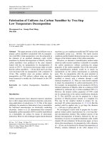
Figure 2.3. Back-scattered electron image showing the difference in contrast due to
the atomic number: (A) observed material and (B) image of back-scattered electrons
(Kim et al., 2010).
Characteristic X-rays are generated when the electron beam ejects an inner shell
electron from the sample, causing outer-shell electron with higher energy to fill the
shell and release energy. The characteristic X-rays energy and wavelength can be
14
measured by energy-dispersed X-ray spectroscopy and wavelength-dispersed X-ray
spectroscopy to identify and quantify the abundance of elements and map their
distribution in the sample (Assumpỗóo Pereira-da-Silva & Ferri, 2017).
The quality of SEM measurement results (particle shape, size) is highly dependent on
sample preparation. SEM samples need to be small enough to fit the specimen stage
and may require special preparation in order to increase their electrical conductivity
and stabilization, thus, they can withstand high vacuum conditions and high energy
electron beams. SEM samples are normally powders or suspensions, which usually
need diluting to create images of discrete particles and to minimize accumulation of
particles.
The sample is often attached firmly on a specimen holder or stub using conductive
adhesive. Non-conductive specimens generally collect charge while scanned by the
electron beam, especially in secondary electron mode, which results in scanning errors
and other imaging artifacts. For the conventional image in the SEM, the samples have
to be conductive, at least on the surface, and electrically grounded to avoid
electrostatic charge buildup. Metal objects commonly require little special preparation
except for usual cleaning and conductively attaching to a specimen stub. Nonconductive materials are regularly coated with an ultra-thin coating of conductive
material, deposited on the sample with a low-vacuum sputtering coating or by highvacuum evaporation. Conductive materials currently used for sample coating are gold,
gold/palladium alloys, tungsten, iridium, platinum, chromium, osmium, and graphite
(Suzuki, 2002).
2.3.2. Energy-dispersive X-ray spectroscopy (EDX or EDS)
Energy-dispersive X-ray spectroscopy is an analytical method use for detection of
elemental composition of a sample by using scanning electron microscope. It is a
nondestructive testing method for investigation of material composition. EDX can
detect elements with a higher atomic number than boron, and these elements need to
be at concentrations of at least 0.1 % for detection (Abd Mutalib et al., 2017). EDX is
one of the main techniques in material science, and also applied in other branches of
science such as physics, chemistry and geology.
15
EDX analysis is based on the interaction of X-ray excitation and the sample. When
colliding with an electron beam in a SEM, the samples interact with the beam and
produce characteristic X-rays. Because no elements have the same X-ray emission
spectrum, they can be discriminated and their concentrations in the sample can be
measured. X-rays are the result of interaction between the primary electron beams with
the nucleus of the sample atom. The primary electron beam will excite the electron in
the atom's nucleus, pushing it out of the nucleus and producing an electron hole. Then,
an electron with higher energy from the outer shell of the atom will replace the ejected
electron and release X-rays. The emitted X-rays include X-rays continuum (generated
by electron deceleration) and characteristic X-ray (produced by the replacement of
outer shell electron to the electron hole in the nucleus shell) (Abd Mutalib et al., 2017).
Each EDX spectrum is formed by different elements and composition existing in the
sample. However, some components represent the overlapping peaks, for instance, TiKβ, V-Kα, Mn-Kβ, and Fe-Kα. Thus, recognition of the overlapping spectra is a
difficult task. According to the principle, incident beams towards the sample surface
help to create specific characteristic X-rays from samples. The resultant characteristic
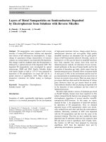
X-rays are then utilized to analyze the sample composition (Figure 2.4). Moreover,
measurement of the characteristic X-ray energy depends on quantity and density of the
material, accuracy of the spectrum and quality of detector. Apart from this, the
inhomogeneity and roughness of samples can also have negative effect to the certainty
of analysis (Mishra et al., 2017).
Figure 2.4. Schematic representation of the types of X-ray spectrum emitted upon
bombardment of fast electron (Reichelt, 2007)
16