Tài liệu cisco migrationn_Network Virtualization—Services Edge Design ppt
Bạn đang xem bản rút gọn của tài liệu. Xem và tải ngay bản đầy đủ của tài liệu tại đây (882.24 KB, 26 trang )
Americas Headquarters:
© 2007 Cisco Systems, Inc. All rights reserved.
Cisco Systems, Inc., 170 West Tasman Drive, San Jose, CA 95134-1706 USA
Network Virtualization—Services Edge Design
Guide
The centralization of access to shared services provides a common point of policy enforcement and
control for all VPNs. This is referred to as the services edge functional area. Services edge has more of
a logical than a physical meaning. In a specific network design, the point of policy enforcement can be
physically located in a specific area of the network, but in certain cases, it might also be spread around
the network.
For related information, see the following documents:
• Network Virtualization—Guest and Partner Access Deployment Guide (OL-13635-01)
• Network Virtualization—Network Admission Control Deployment Guide (OL-13636-01)
• Network Virtualization—Path Isolation Design Guide (OL-13638-01)
Contents
Introduction 2
Services Edge—Document Scope 4
Unprotected Services 4
Protected Services 5
Integrating a Multi-VRF Solution into the Data Center 5
Shared Services Implementation in the Data Center 8
Shared Internet Access—Virtualized Internet Edge Design 11
Firewall in Routed Mode 15
Firewall in Transparent Mode 16
Centralized Web Authentication Services 17
Cisco Clean Access 19
2
Network Virtualization—Services Edge Design Guide
OL-13637-01
Introduction
Introduction
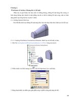
The term network virtualization refers to the creation of logical isolated network partitions overlaid on
top of a common enterprise physical network infrastructure, as shown in
Figure 1.
Figure 1 Network Virtualization
Each partition is logically isolated from the others and must provide the same services that would be
available in a traditional dedicated enterprise network. This essentially means that the experience of the
end user is that of being connected to a dedicated network that provides privacy, security, an independent
set of policies, service level, and even routing decisions.
At the same time, the network administrator can easily create and modify virtual work environments for
the various groups of users, and adapt to changing business requirements in a much easier way. The latter
derives from the ability to create security zones that are governed by policies enforced centrally. Because
policies are centrally enforced, adding users and services to or removing them from a VPN requires no
policy reconfiguration. Meanwhile, new policies affecting an entire group can be deployed centrally at
the VPN perimeter. Thus, virtualizing the enterprise network infrastructure provides the benefits of
leveraging multiple networks but not the associated costs, because operationally they should behave like
one network (reducing the relative operating expenses).
Network virtualization responds to both simple and complex business drivers. As an example of a simple
scenario, an enterprise wants to provide Internet access to visitors (guest access). The stringent
requirement in this case is to allow visitors external Internet access while preventing any possibility of
connection to the enterprise internal resources and services. This can be achieved by dedicating a logical
“virtual network” to handle the entire guest communications. A similar case is where Internet access can
be combined with connectivity to a subset of the enterprise internal resources, as is typical in partner
access deployments.
Another simple scenario is the creation of a logical partition to be dedicated to the machines that have
been quarantined as a result of a Network Access Control (NAC) posture validation. In this case, it is
essential to guarantee isolation of these devices in a remediation segment of the network, where only
access to remediation servers is possible until the process of cleaning and patching the machine is
successfully completed.
221035
Virtual Network
Physical Network Infrastructure
Virtual Network Virtual Network
3
Network Virtualization—Services Edge Design Guide
OL-13637-01
Introduction
As an example of a more complex scenario, an enterprise IT department starts functioning as a service
provider, offering access to the enterprise network to a variety of “customers” that need to be kept
logically isolated from each other. Users belonging to each logical partition can communicate with each
other and can access dedicated network resources, but inter-communication between groups is
prohibited. A typical deployment scenario in this category involves retail stores such as Best Buy,
Albertson’s, Wal-Mart, and so on, that provide on-location network access for kiosks or hotspot
providers.
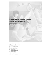
The architecture of an end-to-end network virtualization solution that is targeted to satisfy the
requirements listed above can be separated in three logical functional areas (see
Figure 2):
• Access control
• Path isolation
• Services edge
Figure 2 Network Virtualization—Three Functional Areas
Each area performs several functions and interfaces with the other functional areas to provide a complete
integrated end-to-end solution.
Each of these areas is discussed in great detail in a separate design guide. This document addresses the
requirement of the services edge. For information on the other two functional areas, see the following
guides:
• Network Virtualization— Access Control Design Guide (OL-13634-01)
• Network Virtualization—Path Isolation Design Guide (OL-13638-01)
The virtualization of the enterprise network allows for the creation of a separate logical network that is
placed on top of the physical infrastructure. The default state of these virtual networks (VPNs) is to be
totally isolated from each other, in this way simulating separate physical networks.
221036
GRE
VRFs
MPLS
Access Control
Functions
Path Isolation Services Edge
Branch - Campus WAN – MAN - Campus
Authenticate client (user,
device, app) attempting to
gain network access
Authorize client into a
Partition (VLAN, ACL)
Deny access to
unauthorized clients
Maintain traffic partitioned over
Layer 3 infrastructure
Transport traffic over isolated
Layer 3 partitions
Map Layer 3 Isolated Path to VLANs
in Access and Services Edge
Provide access to services:
Shared
Dedicated
Apply policy per partition
Isolated application environments
if necessary
Data Center - Internet Edge -
Campus
IP
LWAPP
4
Network Virtualization—Services Edge Design Guide
OL-13637-01
Introduction
This default behavior may need to be changed when the various VPNs need to share certain services,
such as Internet access as well as network services such as DHCP and DNS, and server farms.
This document presents alternative ways to accomplish this sharing of resources between various VPNs.
The services that need to be shared are discussed, as well as the distinction between protected and
unprotected services. This document broadly categorizes services that are shared by many VPNs as
either protected or unprotected, depending on how they are accessed.
Various technologies are discussed that achieve the sharing of resources between different network
partitions. To make good use of this document, note the following:
• The various technologies are discussed in the context of the network virtualization project. This
means that for these technologies, the details that have been validated and positioned as part of the
network virtualization project to provide an answer to the business problems previously listed are
discussed.
• Not all the technologies found in this design guide represent the right fit for each business problem.
For example, there may be scenarios (such as guest access) where resources are dedicated to the
specific virtual network and no sharing at all is required. To properly map the technologies discussed
here with each specific business problem, reference the following deployment guides:
–
Network Virtualization—Access Control Design Guide (OL-13634-01)
–
Network Virtualization—Guest and Partner Access Deployment Guide (OL-13635-01)
–
Network Virtualization—Network Admission Control Deployment Guide (OL-13636-01)
–
Network Virtualization—Path Isolation Design Guide (OL-13638-01)
Services Edge—Document Scope
The services edge portion of the overall network virtualization process is where a large part of policy
enforcement and traffic manipulation is done. Before the services edge is implemented, it is important
to thoroughly understand which methodology is to be deployed and what the trade-offs are for selecting
the methods described in this guide. It is also important for customers to understand their applications
and their associated traffic flows to help in the overall network optimization process.
This guide accomplishes the following:
• Provides guidelines on how to accomplish the integration of multi-VPN Routing and Forwarding
(VRF) solutions into the data center core layer while using the core nodes as provider edge (PE)
routers.
• Presents implementation options for providing shared services in a multi-VRF environment using
the Cisco Application Control Engine (ACE) and the Cisco Firewall Services Module (FWSM).
• Distinguishes between protected and unprotected services, and discusses the design of the services
edge to allow shared access to the most typical shared resource, which is the Internet.
• Describes the use of web authentication appliances to authenticate and authorize users before
permitting Internet access. This is a common requirement in the enterprise arena when providing
guest access services to visitors, but can also be leveraged in various contexts.
Although this guide addresses many technical areas, it does not address during this phase of the network
virtualization project the following areas:
• Placing of voice services or multicast services into a VRF.
• Use of overlapping IP addresses in the VRFs. IP address overlap may be addressed in the future; the
major reason for not addressing it in this guide is because of the operational impacts that this causes
to customer networks in the operations and management aspects of the network infrastructure.
5
Network Virtualization—Services Edge Design Guide
OL-13637-01
Integrating a Multi-VRF Solution into the Data Center
Unprotected Services
An unprotected service is a service that can be accessed openly without subjecting the traffic to any type
of security check. An unprotected service is reachable from one or more VPNs without having a policy
enforcement point between the service and the requesting host. The best path routes to reach an
unprotected service can be present in the various VPNs that can access the service.
In general, this type of access is used to provide shared DHCP or DNS services to the various VPNs
without adding an unnecessary load to the firewalls that are being used to control access to other shared
services that must be protected.
Protected Services
Protected services must be accessible from the VPNs, but only after specific security policies are
enforced. To be able to enforce the necessary security policies in a manageable way, access to the
services must go through a policy enforcement point. Thus, all traffic reaching the services must be
routed through a common point of policy enforcement. As a result, the routing between a requesting host
and a service can potentially be less than optimal. However, this is true only in very specific scenarios,
such as when the shared services themselves are part of a VPN. In general, shared services that are to be
protected are centrally located for optimal accessibility.
Examples of protected services include server farms and the Internet. When accessing the Internet, not
only is it necessary to control access to the service from the VPNs, but it is also critical to control any
access initiated from the service area towards the VPNs. Ideally, none of the VPNs should be accessed
from the Internet; thus access into the VPNs from the services area is generally prohibited.
In cases where VPNs must communicate with each other in a controlled manner, the policies at the VPN
perimeter can be changed to provide such access. In this particular inter-VPN connectivity application,
the policies must be open to allow externally-initiated communication into the VPNs.
Integrating a Multi-VRF Solution into the Data Center
One of the most common implementations of a multi-VRF solution is in data center consolidation, which
allows multiple applications to reside in one central facility and to share a common WAN infrastructure
that services more than one customer segment.
Benefits of this solution include the ability to consolidate data centers during a merger or acquisition, or
the ability to offer tenant-type services for various locations. This solution allows the common WAN
infrastructure to be virtualized across multiple departments or customers, and allows them to maintain
separation from their data center resources all the way to their branch locations.
The actual implementation of this solution requires that the core nodes be treated as the PE routers if you
are using a Multiprotocol Label Switching (MPLS) network. The reasons for not extending the core
routing further into the data center are that doing so introduces core routing into the facility, and thus
reduces convergence times in the event of a physical link problem in the data center. It also mandates the
use of a larger memory pool to support the data center Interior Gateway Protocol (IGP), Border Gateway
Protocol (BGP) for MPLS reachability, and then the actual VRF route tables. This can limit platform
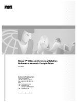
selection by the customer and also affect services deployment in the data center.
Terminating the VRFs on the PE routers in the core maintains a clean separation of the WAN/data center.
(See
Figure 3.) This eliminates the need for appliances or services modules to become VRF-aware,
which can potentially impact the data center design as it scales to support a larger server install base as
servers are consolidated. This is because many services appliances and services modules are not
6
Network Virtualization—Services Edge Design Guide
OL-13637-01
Integrating a Multi-VRF Solution into the Data Center
currently MPLS VRF-aware. Sub-interfaces are used for the VRFs because it is assumed that the global
table will be the existing network for a customer seeking to deploy a virtualized network. Creating the
virtualized network out of sub-interfaces avoids the need to make changes to this table, and there is no
impact to the global table as you migrate to this new environment.
Figure 3 Terminating the VRFs on the PE Routers in the Core
The following shows the ingress PE (Catalyst 6500-core data center switch) VRF 1 configuration:
ip vrf v1
rd 64001:1
route-target export 64000:1
route-target import 64000:1
!
mpls label protocol ldp
tag-switching tdp discovery hello interval 1
tag-switching tdp discovery hello holdtime 3
tag-switching tdp router-id Loopback10 force
!
interface TenGigabitEthernet1/3
description 10GE to cr15-6500-1 (DC Aggr. 1)
ip address 10.136.0.4 255.255.255.254
ip hello-interval eigrp 100 1
ip hold-time eigrp 100 3
ip authentication mode eigrp 100 md5
ip authentication key-chain eigrp 100 eigrp
ip pim sparse-mode
load-interval 30
tag-switching ip
mls qos trust dscp
!
interface TenGigabitEthernet1/3.201
description link to cr15-6500-1 (v1)
encapsulation dot1Q 201
ip vrf forwarding v1
ip address 10.136.0.20 255.255.255.254
ip hello-interval eigrp 100 1
ip hold-time eigrp 100 3
ip authentication mode eigrp 100 md5
VPNRed
VPNGreen
802.1Q
VPNBlue
VPN Green Site
C1
MPLS
Network
Egress PE
Catalyst 6500
Distribution CE
Interface 1/1
Ingress PE
(Catalyst 6500-Core)
Interface 1/3
VPN Blue Site
C1
VPN Red Site
C1
Each SubInterface
associated with
different VRF
221037
7
Network Virtualization—Services Edge Design Guide
OL-13637-01
Integrating a Multi-VRF Solution into the Data Center
ip authentication key-chain eigrp 100 eigrp
!
address-family ipv4 vrf v1
redistribute bgp 64000 metric 100000 0 255 1 1500 route-map routes_to_DC
network 10.0.0.0
distribute-list 40 in
no auto-summary
autonomous-system 100
exit-address-family
!
address-family ipv4 vrf v1
redistribute eigrp 100
maximum-paths ibgp 8 import 6
no auto-summary
no synchronization
exit-address-family
!
no logging event link-status boot
logging event link-status default
logging 172.26.158.251
access-list 40 permit 10.136.0.0 0.0.255.255
access-list 40 permit 13.0.0.0 0.255.255.255
access-list 41 permit 10.136.254.0 0.0.0.255
cdp timer 5
!
route-map routes_from_DC permit 10
match ip address 40
The following shows the Catalyst 6500 distribution customer edge (CE) configuration:
svclc multiple-vlan-interfaces
svclc module 3 vlan-group 2,3
svclc vlan-group 1 900-905,950,960
svclc vlan-group 2 970,980,1050-1055
svclc vlan-group 3 2,12,22,32,42,52
firewall multiple-vlan-interfaces
firewall module 4 vlan-group 1,2
ip subnet-zero
!
ip vrf v1
rd 64001:1
!
vlan 2
name Voice_VLAN_1_Global
!
vlan 12
name Voice_VLAN_1_v1
!
vlan 181
name transit_v1
!
vlan 900
name global-table-fwsm-ingress
!
vlan 901
name vrf-1-fwsm-ingress
!
vlan 1051
name vrf-1-ace-ingress
!
interface TenGigabitEthernet1/1
description 10GE to cr14-6500-1 (DC core 1)
ip address 10.136.0.5 255.255.255.254
8
Network Virtualization—Services Edge Design Guide
OL-13637-01
Shared Services Implementation in the Data Center
ip hello-interval eigrp 100 1
ip hold-time eigrp 100 3
ip authentication mode eigrp 100 md5
ip authentication key-chain eigrp 100 eigrp
ip pim sparse-mode
load-interval 30
mls qos trust dscp
interface TenGigabitEthernet1/1.201
description link to cr14-6500-1 (v1)
encapsulation dot1Q 201
ip vrf forwarding v1
ip address 10.136.0.21 255.255.255.254
ip hello-interval eigrp 100 1
ip hold-time eigrp 100 3
ip authentication mode eigrp 100 md5
ip authentication key-chain eigrp 100 eigrp
!
interface Vlan181
description transit to cr15-6500-2 (v1)
ip vrf forwarding v1
ip address 10.136.0.180 255.255.255.254
ip hello-interval eigrp 100 1
ip hold-time eigrp 100 3
ip authentication mode eigrp 100 md5
ip authentication key-chain eigrp 100 eigrp
!
interface Vlan901
description vrf-1-fwsm-ingress
mac-address 0000.0000.0080
ip vrf forwarding v1
ip address 10.136.12.3 255.255.255.0
load-interval 30
standby 1 ip 10.136.12.1
standby 1 timers msec 250 msec 750
standby 1 priority 105
standby 1 preempt delay minimum 180
standby 1 authentication ese
!
address-family ipv4 vrf v1
network 10.0.0.0
no auto-summary
autonomous-system 100
exit-address-family
!
ip route vrf v1 10.136.2.133 255.255.255.255 10.136.2.133 global
!
arp vrf v1 10.136.12.248 0000.0000.0208 ARPA
Shared Services Implementation in the Data Center
Implementation of shared services in the data center treats the services to be shared no differently than
any other VLAN or VPN defined, with the exception that this VPN exports its routes to most if not all
of the other VPNs that exist in the network. The shared services VRF also needs to statically route into
the global table until software support allows for importing and exporting of routes from the global table
into a VRF. This support is available today on many routing platforms, but is not available until the
Whitney 1.0 software release on the Cisco Catalyst 6500 product line. Using import and export
commands allows the data center to act as the central policy enforcement area and to create a high
capacity exchange framework between all VPNs, whether or not they need to reach services. The idea
9
Network Virtualization—Services Edge Design Guide
OL-13637-01
Shared Services Implementation in the Data Center
here is to use access control lists (ACLs) to act as a first line of policy enforcement to allow VPNs to
communicate to each other. Then within each VPN or VLAN, you can use the FWSM and ACE and their
individual context capability to further manipulate traffic. (See
Figure 4.)
Figure 4 Service Creation in the Distribution Layer
Careful consideration must be made in the distribution layer in the allocation of VLAN assignments and
the termination of the VRFs. It is important to understand the service chaining needed for each customer
environment and whether policies can be shared. If transparent operation mode is to be implemented,
you must ensure that Bridge Protocol Data Unit (BPDU) forwarding is enabled in both the FWSM and
the ACE module.
For more information on service chaining and failover of services modules, see Service Module Design
with ACE and FWSM at the following URL:
The next consideration is how to allow the shared services to be used by users in the global route table,
and then the individual Customer VRFs.
The simplest method for doing this is to use simple static routing into the global table. (See Figure 5.)
221038
v108
BU-1 BU-2 BU-3 BU-4
v205
v105
v5
v206
v106
v6
v107
v7
v108
v8
v107v206
Simplicity
Functionality
v2051
v2052
v2053
10
Network Virtualization—Services Edge Design Guide
OL-13637-01
Shared Services Implementation in the Data Center
Figure 5 Shared Services—Sharing with Global Table
After the services are working with the global table, the next area to address is sharing services between
the VRFs. Again, this is accomplished through the use of export and import commands on the individual
VRFs. The important thing to consider here is what are the application interdependencies, and whether
any unique traffic patterns might dictate using shared versus non-shared resources. Before doing this,
thoroughly examine the customer application environment to ensure that resources are positioned
correctly for application optimization.
As an example, assume a customer has a home-grown application that relies heavily on DNS and Layer
2 communications between several organizations servers. It would not be advisable to insert Layer 3
boundaries into this environment until you can determine what the impact would be to the application.
The other method of allowing communication between the VPNs is to implement a data center fusion
VRF to allow for shared Internet access. (See
Figure 6.)
ip route 10.136.254.10 255.255.255.255 Vlan926
ip route vrf services 10.137.61.0 255.255.255.0 10.136.0.4 global
ip route vrf services 10.137.61.0 255.255.255.0 10.136.0.8 global
ip route 10.136.254.10 255.255.255.255 Vlan926
ip route vrf services 10.137.61.0 255.255.255.0 10.136.0.6 global
ip route vrf services 10.137.61.0 255.255.255.0 10.136.0.10 global
VPN Services
10.136.254.10
10.137.61.200
cr20-6500-2cr20-6500-1
cr14-6500-2
cr14-6500-1
cr15-6500-1
cr15-6500-2
.4
.6
.8
.10
221039
11
Network Virtualization—Services Edge Design Guide
OL-13637-01
Shared Services Implementation in the Data Center
Figure 6 Shared Services—Sharing with Global Table
This method has the advantages of allowing every VRF that would need access to the shared services to
have their own service chain created and thus their own shared services policy implemented. Depending
on the services contained in the shared services VRF, this can be either advantageous or unnecessary.
Again, a thorough understanding of the customer environment is needed to make the design decision.
Using the fusion router type solution almost certainly requires the implementation of the ACE and
FWSM modules in multiple context mode, while the first shared services model can be implemented
with the FWSM and Cisco Content Services Module (CSM) with both in a potentially non-contexted
solution.
ip vrf services
rd 64001:26
route-target export 64000:26
route-target import 64000:1
route-target import 64000:2
ip vrf v1
rd 64001:1
route-target export 64000:1
route-target import 64000:1
route-target import 64000:26
!
ip vrf v2
rd 64001:2
route-target export 64000:2
route-target import 64000:2
route-target import 64000:26
ip vrf v1
rd 64002:1
route-target export 64000:1
route-target import 64000:1
route-target import 64000:26
!
ip vrf v2
rd 64002:2
route-target export 64000:2
route-target import 64000:2
route-target import 64000:26
ip vrf services
rd 64002:26
route-target export 64000:26
route-target import 64000:1
route-target import 64000:2
VPN Services
10.136.254.10
cr20-6500-2cr20-6500-1
cr14-6500-2
cr14-6500-1
cr15-6500-1
cr15-6500-2
.4
.6
.8
.10
10.137.15.200
10.137.25.200
221040
VPN v1
VPN v2
12
Network Virtualization—Services Edge Design Guide
OL-13637-01
Shared Internet Access—Virtualized Internet Edge Design
Shared Internet Access—Virtualized Internet Edge Design
To allow secured communication between each VPN and the Internet, it is necessary to create unique
points of ingress and egress to each defined virtual network. This can be achieved by configuring the
routing inside each VPN to forward traffic destined outside the VPN to a specific gateway. When traffic
reaches this gateway, it can be controlled by means of ACLs, firewalls, intrusion detection systems, or
any other in-band security mechanisms that are considered necessary.
This is the equivalent of treating each VPN as if it were a physically separate network. Separate networks
connecting to a common resource must have a security device head-end to control access to the network.
The device typically used for this is a firewall. When accessing the Internet, the place in the network
where such a firewall is deployed is known as the Internet edge.
Figure 7 illustrates a typical perimeter
deployment for multiple VPNs accessing common services.
Figure 7 Internet Edge Design
In the network diagram in Figure 7, it is assumed that a separate VRF instance for each VPN is defined
on the PE device in the Internet edge. However, a similar design where distributed ACLs are the
mechanism deployed for path isolation can also be used in the scenario, as described in the Network
Virtualization—Path Isolation Design Guide. In that case, no VRFs are defined and the traffic might be
steered to a separate firewall by using policy-based routing (PBR).
As seen in Figure 7, each VPN is head-ended by a dedicated firewall. This allows for the creation of
security policies that are specific to each VPN, independent of each other. To access the shared services,
all firewalls are connected to a fusion router. The fusion router can provide the VPNs with connectivity
to the Internet or inter-VPN connectivity. Separate load balancers can also be deployed per VPN to create
a complete service chain on a per-VPN basis (this is more relevant when deploying this model for
accessing shared resources located in a data center).
The use of a fusion router raises two main concerns: the potential for traffic leaking between VPNs, and
the risk of routes from one VPN being announced to another VPN. Having dedicated per-VPN firewalls
prevents the leaking of traffic between VPNs through the fusion router by allowing only established
connections to return through the VPN perimeter. It is important to configure the routing on the fusion
device so that it does not advertise the routes from one VPN to another VPN. See
Firewall in Routed
Mode, page 15 and Firewall in Transparent Mode, page 16 for more information.
Figure 7 shows an additional firewall separating the fusion area from the Internet. This firewall is
optional, and is used to keep common services or transit traffic in the fusion area protected from the
Internet.
Campus
Core
Internet
VPN A
PE
153681
Internet
Edge
Router
VPN B
VPN C
VPN D
(Optional)
13
Network Virtualization—Services Edge Design Guide
OL-13637-01
Shared Internet Access—Virtualized Internet Edge Design
The information in the following section, even though largely focused on providing Internet access, can
be generalized to provide access to any resource external for a VPN. An external resource can also
include resources in other VPNs; thus a resource in VPN A is considered an external resource for VPN
B and it is therefore accessed through the secure VPN perimeter. This scenario is illustrated in
Figure 8.
Figure 8 Shared Internet Access
The use of service chaining allows for each VPN to have its own internal policy domain. This same
service chaining can easily be applied to the fusion VRF to allow for a common policy to be applied to
all users going to the Internet. This in effect simplifies the internal VPN policies because you can layer
security and load balancing solutions instead of having to create a new policy for each VPN.
As the number of VPNs increases, head-ending each VPN onto its own firewall can become expensive
and hard to manage. Cisco firewalls can be virtualized, and therefore offer a separate context for each
VPN on the same physical appliance. The resulting topology is shown in
Figure 9. Note that a single
physical firewall provides a dedicated logical firewall to each VPN.
(cont)
!
arp vrf v2 10.136.22.248 0000.0000.0208 ARPA
arp vrf v1 10.136.12.248 0000.0000.0208 ARPA
arp vrf fusion 10.136.12.3 0000.0000.0080 ARPA
arp vrf fusion 10.136.22.3 0000.0000.0080 ARPA
(cont)
interface Vlan 101
description L3_peering_fusion
ip vrf forwarding fusion
ip address 10.136.101.1 255.255.255.0
load-interval 30
!
router e igrp 100
no passive-interface Vlan2
no passive-interface Vlan12
no passive-interface Vlan22
no passive-interface Vlan900
no passive-interface Vlan901
no passive-interface Vlan902
network 10.0.0.0no auto-summary
!
address-family ipv4 vrf fusion
network 10.0.0.0
no auto-summary
autonomous-system 100
exit-address-family
ip vrf fusion
rd 64001:100
!
interface Vlan 2
description global to fusion VRF
mac-address 0000.0000.0208
ip vrf forwarding fusion
ip address 10.136.2.248 255.255.255.0
load-interval 30
!
interface Vlan 12
description VRF v1 to fusion VRF
mac-address 0000.0000.0208
ip vrf forwarding fusion
ip address 10.136.12.248 255.255.255.0
!
interface Vlan 22
description VRF v2 to fusion VRF
mac-address 0000.0000.0208
ip vrf forwarding fusion
ip address 10.136.22.248 255.255.255.0
!
interface Vlan 100
description Fusion Vrf
ip vrf forwarding fusion
ip address 10.136.100.3 255.255.255.0
standby 1 ip10.136.100.1
standby 1 priority 105
standby 1 preempt delay minimum 180
VPN v2
cr15-6500-1
VLAN 900
VLAN 901
VLAN 2
VLAN 100
Fusion VRF
Internet
VLAN 12
221041
Global
VPN v1
VLAN 902
VLAN 22
14
Network Virtualization—Services Edge Design Guide
OL-13637-01
Shared Internet Access—Virtualized Internet Edge Design
Figure 9 Internet Edge with Virtual Firewall
The concept of virtual firewalls or firewall contexts has been implemented on Cisco firewall appliances,
as well as in the integrated FWSM for the Cisco Catalyst 6500. The integration of the firewall
functionality onto the PE platform allows the topology shown to be consolidated onto a single physical
device, as shown in
Figure 10. The logical topology remains unchanged. The firewall functionality is
carried out by an FWSM within the PE, and the fusion router is implemented by the creation of a VRF
inside the same PE. Also note, in
Figure 10, how the fusion VRF acts as a separate router.
Figure 10 Internet Edge (Single Box Implementation)
To provide a resilient solution, Cisco recommends deploying a redundant pair of PE devices in the
Internet edge, and equipping each one with its own firewall module.
The routing between the fusion router, the various contexts, and the VPNs must be configured with care.
Because of its place in the topology, the fusion router has the potential to mix the routes from the various
VPNs when exchanging routes dynamically with the various VPNs. The following two scenarios to
prevent this can be considered, depending on the mode of operation of the firewall:
• Firewall in routed mode
FW
VFW
Campus
Core
Internet
VPN A
PE
153683
Internet
Edge
Router
VPN B
VPN C
VPN D
VFW
VFW
VFW
FW
VFW
Campus
Core
Internet
VPN A
153684
Internet
Edge
Router
VPN B
VPN C
VPN D
VFW
VFW
VFW
PE router + perimeter FW + internet edge router
15
Network Virtualization—Services Edge Design Guide
OL-13637-01
Shared Internet Access—Virtualized Internet Edge Design
• Firewall in transparent mode
It is recommended to deploy the Internet edge separately from the data center shared services design. In
effect, this creates two separate policy domains that can be layered together to create a stronger overall
security posture. Inter-VPN traffic should be handled as outlined previously concerning how to share
traffic between VPNs, and Internet edge traffic should be handled as a separate use case.
Firewall in Routed Mode
When configured for multiple contexts, the firewall in routed mode supports only static routing, so the
mixing of VPN routes is not a concern. Connectivity between VPNs is achieved by the sole configuration
of the fusion router. However, the firewalls are configured to allow only established connections (only
connections that are initiated from inside of the firewall). Thus, all VPNs can reach the fusion router,
and the fusion router can return traffic to all the VPNs. However, the VPNs are unable to communicate
with each other through the fusion router unless very specific policies are set on the various firewall
contexts to allow inter-VPN communication through the VPN perimeter gateway.
The static routing configuration for the perimeter gateway is illustrated in Figure 11 and is described in
the steps that follow the illustration. Details are provided for one VPN only; other VPNs require similar
configuration. Note that Network Address Translation (NAT) can be used in this configuration because
the firewalls are in routed mode, and this allows support for overlapping IP addresses in various VPNs.
Figure 11 Firewalls in Routed Mode
Step 1 Create a default route for the internal VRF (VPN-A):
6500-PE(config)#ip route vrf VPN-A 0.0.0.0 0.0.0.0 172.18.1.2
Step 2 Create a static route for the inside of the firewall to reach the internal networks:
FWSM/VPN-A(config)#route inside 172.18.0.0 255.255.0.0 172.18.1.1
Step 3 Create a static default route for the outside of the firewall to send traffic to the fusion router or VRF:
FWSM/VPN-A(config)#route outside 0.0.0.0 0.0.0.0 172.18.1.1
Step 4 Configure dynamic NAT functionality:
FWSM/VPN-A(config)#global (outside) 1 209.165.201.3-209.165.201.7 netmask 255.255.255.248
FWSM/VPN-A(config)#nat (inside) 1 172.18.0.0 255.255.0.0
Internet
VPN A
153685
Internet
Edge
Router
VPN B
VPN C
VPN D
Inject Default
Route
Default
Route
Static Route
to internal
network
172.18.1.0/30
209.165.201.0/29
Default
Route
Directly
connected
(NAT)
Default
Route
125.1.7.224/30
NAT
16
Network Virtualization—Services Edge Design Guide
OL-13637-01
Shared Internet Access—Virtualized Internet Edge Design
Step 5 Allow outbound connectivity through the firewall (from the internal VPN-A toward the Internet):
FWSM/VPN-A(config)#access-list allow_any extended permit ip any any log debugging
FWSM/VPN-A(config)#access-group allow-any in interface inside
Note In this example, all IP traffic is allowed from the inside toward the Internet. Depending on the
characteristics of the specific VPN, the ACL can be restricted to allow only specific ports or protocols.
The fusion router is able to reach the outside prefixes because they are directly connected. No
configuration is required.
Step 6 Create a static default route for the fusion router and VRF to communicate with the ISP:
6500-PE(config)#ip route vrf fusion 0.0.0.0 0.0.0.0 125.1.7.226
Note This is the standard configuration for an Internet access router, and it is therefore not covered in detail
in this document.
Step 7 Insert the default route created in Step 1 into the routing protocol that is enabled in the context of the
VRF.
The configuration used here depends on the specific routing protocol deployed; the injection of the
default route can generically be enabled through the redistribute static command. Also, the specific
routing protocol needs to be enabled to advertise a default route.
Firewall in Transparent Mode
Deploying firewalls in transparent mode simplifies the routing, and allows complete functionality to be
achieved by means of IGPs, as shown in
Figure 12.
Figure 12 Firewalls in Transparent Mode
Internet
VPN A
153686
Internet
Edge
Router
VPN B
VPN C
VPN D
Inject Default
Route
172.18.1.0/30
209.165.201.0/29
125.1.7.224/30
IGP
Default
Route
17
Network Virtualization—Services Edge Design Guide
OL-13637-01
Centralized Web Authentication Services
The fusion router adds a default route into the IGP that is enabled in the context of each VRF. Because
of the bridged nature of the firewalls, it is possible to establish the peering between the VRFs and the
fusion router directly with an IGP. It is not possible to use the firewalls for NAT, so all VRFs must use
valid and unique IP address spaces (no support for overlapping IP addresses).
This configuration is very simple and consists of the following steps. This is a standard Internet edge
configuration and it must be done for each VPN.
Step 1 Create a default route pointing to the Internet on the fusion router/VRF. For example:
ip route vrf fusion 0.0.0.0 0.0.0.0 125.1.7.226
Step 2 Advertise the default route in the IGP used between the fusion router and the VRFs at the PE.
Step 3 Filter the routing updates between the VRFs at the fusion router to avoid advertising routes from one
VRF into another. The communication between VRFs is prevented by the default behavior of the
firewall, which allows only internally initiated connections. Therefore, with the default firewall policies,
a connection initiated from VPN A to VPN B is allowed through the VPN A firewall context, but is
rejected by the VPN B context, because that would be considered an externally initiated connection.
Cisco recommends keeping the routes from being populated across VRFs and allowing these updates to
pass through only when you want inter-VRF communication.
Step 4 Include static ARP entries to allow the VPNs and the fusion VRF to communicate. Without the static
ARP entries, the interfaces would all have the same MAC address and routing between them would not
be possible.
arp vrf v2 10.136.22.248 0000.0000.0208 ARPA
Centralized Web Authentication Services
The use of a centralized web authentication mechanism might be required for several reasons, such as
the following:
• Preventing unauthorized users from being able to exploit the enterprise network to connect to a
specific shared resource (such as the Internet)
• Enforcing the acceptance of a legal disclaimer before allowing access to protected resources from
the enterprise network
• Creating a form of management control over the user session, with regard to such things as
determining the maximum session duration, disabling access at any given moment (if needed), and
having an audit trail to track user activity
Note The web authentication functionality can be leveraged to prevent the access to any generic area of the
network. However, the most common application is to force users to authenticate before obtaining access
to the Internet, so this is the scenario that is used for the rest of this section.
The clear advantage of the web authentication is that no specific software needs to be installed on the
user machine to trigger the authentication process. This is a key factor, given the lack of control that an
enterprise might have on the devices of specific categories of users (for example, guests). The web
authentication process is triggered every time a user tries to access a website using any generic web
browser, and usually causes the interception and redirection to a specific portal to allow the provision of
authentication credentials (or even simply to confirm the acceptance of a legal disclaimer).
18
Network Virtualization—Services Edge Design Guide
OL-13637-01
Centralized Web Authentication Services
In the design described in this document, the web authentication functionality is performed by a specific
appliance deployed in-band (on the data path) in a centralized location. The user traffic must be enforced
through the web authentication appliance for the initial interception and redirection processes to happen.
At the same time, traffic still needs to flow through the device, even after the authentication process is
completed (this is also true for the return traffic from the Internet).
Following the above approach, standalone web authentication platforms are typically deployed in the
Internet edge of the enterprise network. Leveraging the network virtualization techniques previously
covered, guest traffic is forced to the outside (untrusted) interface of the web authentication appliance,
as shown in
Figure 13.
Figure 13 Web Authentication Leveraging a Centralized Appliance
As shown in Figure 13, deploying the web authentication device in a centralized manner means that all
the traffic must be enforced through it, regardless of where it originated (either the campus edge or
branch locations).
Currently, Cisco recommends the deployment of Cisco Clean Access, also known as Cisco NAC
Appliance, which can be deployed as a standalone web authentication device (to be used for both wired
and wireless traffic).
The following sections describe the relevant features for deploying Cisco Clean Access in a centralized
manner for providing web-authentication services to the enterprise.
Campus
Core
WAN
Internet Edge
Building
Internet
WAN
Branch
Data Center
WLSM
WLSM
153687
Web-auth
device
19
Network Virtualization—Services Edge Design Guide
OL-13637-01
Centralized Web Authentication Services
Cisco Clean Access
Cisco Clean Access is an easily deployed Network Admission Control (NAC) solution that can
automatically detect, isolate, and clean infected or vulnerable devices that attempt to access the network,
regardless of the access method. Cisco Clean Access identifies whether networked devices, such as
laptops, personal digital assistants, or even game consoles, are compliant with the network security
policies, and repairs any vulnerability before allowing network access.
The components of the Cisco Clean Access solution are the Clean Access Manager (CAM, the
management station) and the Clean Access Server (CAS, the enforcement point), which run on
Linux-based OS servers. When deploying Cisco Clean Access to provide web authentication, only the
following subset of features is required:
• Performance—Cisco Clean Access allows achieving 1 Gbps throughput with 2000 concurrent user
authentications.
• Customizable portal—CAS redirects users to a customizable splash web page.
• Temporary credential management (access codes)—Starting with software release 3.5.8, an API is
made available for dynamic token user access generation. This provides the following capabilities:
–
Web access to the Cisco Clean Access API to create a user ID and associate an access code to
be used as a password (valid for a specific day) and to assign the user to a role
–
Ability to delete all users associated with that role for that day
–
Ability to list all user names associated with that role
Note To leverage this API, the front-end website needs to be generated separately (it is not provided
with Cisco Clean Access). Also, a limitation of this approach is the lack of billing capabilities
(other than basic RADIUS accounting).
• Authentication, authorization, and accounting (AAA)—Cisco Clean Access provides support for
user authentication within a local database, and can also leverage an external RADIUS server for
authentication and accounting services.
• Session management—At any point in time, it is possible to verify through the session management
interface which users are connected to the network. The administrator can thus disconnect any user
at any time if malicious activity is detected.
• Bandwidth throttling—Shared or dedicated bandwidth can be assigned for each user role. This
feature is not very common in enterprise deployments.
• High availability—Cisco Clean Access supports two-node Clean Access Manager and server
clusters in which a standby server backs up a primary server. The standby server monitors the health
of the primary server via a heartbeat signal exchanged on a dedicated Ethernet or serial connection.
If the standby server cannot detect a heartbeat signal from the primary server, it takes over the
activities of the primary server.
Note The failover process is stateful, so users do not need to re-authenticate when the standby server
becomes active.
20
Network Virtualization—Services Edge Design Guide
OL-13637-01
Centralized Web Authentication Services
• Network scanning—Release 3.5(3) introduced support for multi-hop Layer 3 in-band deployments.
This allows performing basic network scan functionality on clients that are not Layer 2 adjacent to
the Clean Access Server. Note that to perform this network scan, there is no requirement to install
any client software on the user machine. The operation is triggered simply by invoking a web
browser.
A complete analysis of Cisco Clean Access characteristics and features is beyond the scope of this
document. For more information, see the following URL:
/>Some design considerations and configuration guidelines are provided in the following sections. Again,
the assumption is that the CAS addresses have already been configured correctly, as shown in
Figure 14,
and that there is network connectivity between the clients and the CAS itself.
Figure 14 CAS Interface Configuration
As you can see in Figure 14, the CAS is provided with two interfaces. When deployed in a centralized
design, the untrusted interface faces the internal network (where client connection attempts are
received), and the trusted interface is the one facing the outside world. Also, to be deployed in a routed
and centralized scenario, the CAS must be configured to work in Real-IP Gateway mode (working as a
router from a network standpoint).
The configuration steps to achieve the web authentication capability are as follows.
Step 1 Define a managed subnet.
21
Network Virtualization—Services Edge Design Guide
OL-13637-01
Centralized Web Authentication Services
For the CAS to activate the web authentication process, the source IP address of the received traffic needs
to be originated from a managed subnet, which is configured as shown in
Figure 15.
Figure 15 Defining a Managed Subnet
Step 2 Define static routing.
As shown in Figure 15, the default gateway for the CAS is usually configured to point toward the outside
world. As a consequence, to enable communication between the CAS and the users located in the remote
subnets, you need to configure static routes, as shown in
Figure 16.
22
Network Virtualization—Services Edge Design Guide
OL-13637-01
Centralized Web Authentication Services
Figure 16 Configuring Static Routing
Step 3 Configure the DHCP server (optional).
The CAS can also be configured to perform DHCP services. However, this modality cannot be leveraged
when deploying the CAS in a centralized design. The main reason for this is that the CAS was originally
designed as a Layer 2 device (assuming Layer 2 adjacency with the clients). As a consequence, the CAS
is able to provide IP addresses from different DHCP pools only when receiving the DHCP requests on
different VLANs. This is not the case in a centralized scenario, where all the DHCP requests originated
on the remote subnets are forwarded to the CAS by the remote network devices (leveraging the DHCP
relay functionality) and are received on the same VLAN (assigned to the CAS untrusted interface). For
this reason, the only solution is to leverage an external DHCP server.
Step 4 Create Roles.
A useful feature that the Cisco Clean Access solution provides is the ability to define user roles and
associate policies to them. In the guest Internet access example, there are two roles that are relevant:
• Unauthenticated role (predefined by default)—This represents the role to which all of the users are
assigned before successfully authenticating.
• Guest role—This must be explicitly configured, and represents the role to which the users are
assigned after completing the web authentication process. The guest role can be created as shown
in Figure 17.
23
Network Virtualization—Services Edge Design Guide
OL-13637-01
Centralized Web Authentication Services
Figure 17 Creating a Guest Role
Note that specific policies can be applied to each role. These policies have the format of router ACLs
and can allow or deny any type of traffic based on Layer 3 or Layer 4 information. For this specific
example, assuming that DHCP and DNS services are offered by an external server placed on the external
side of CAS, it is mandatory to enable a policy to allow DHCP and DNS requests for the user belonging
to the unauthenticated role because these processes are required before the web authentication can be
triggered. These specific policies are shown in
Figure 18.
24
Network Virtualization—Services Edge Design Guide
OL-13637-01
Centralized Web Authentication Services
Figure 18 Unauthenticated Role Policy
For the guest role (and for any other defined role), it is the responsibility of the network administrator
to specify the particular policy that needs to be enabled. In this example, all IP traffic is allowed (see
Figure 19).
25
Network Virtualization—Services Edge Design Guide
OL-13637-01
Centralized Web Authentication Services
Figure 19 Guest Role Policy
Step 5 Test connectivity to the Internet.
When a client launches the web browser and tries to connect to the Internet, the traffic is enforced
through the CAS, the interception mechanism is invoked, and the Login screen is displayed to allow the
user to enter the authentication credentials (see
Figure 20). Note that the credential for the user can be
created locally on the CAM or on a backend authentication server. See the Cisco Clean Access
documentation for more information on how to do this at the following URL:
/>