Tài liệu Kinematics and Mechanisms P2 docx
Bạn đang xem bản rút gọn của tài liệu. Xem và tải ngay bản đầy đủ của tài liệu tại đây (242.06 KB, 20 trang )
V = kW x=H (21:5)
where V is the volume worn away, W is the normal load, x is the sliding distance, H is the hardness
of the surface being worn away, and k is a nondimensional wear coefficient dependent on the
materials in contact and their exact degree of cleanliness. The term k is usually interpreted as the
probability that a wear particle is formed at a given asperity encounter.
Equation (21.5) suggests that the probability of a wear-particle formation increases with an
increase in the real area of contact,
A
r
(A
r
= W=H for plastic contacts), and the sliding distance.
For elastic contacts occurring in materials with a low modulus of elasticity and a very low surface
roughness Eq. (21.5) can be rewritten for elastic contacts (Bhushan's law of adhesive wear) as
[Bhushan, 1990]
V = k
0
W x=E
c
(¾
p
=R
p
)
1=2
(21:6)
where k
0
is a nondimensional wear coefficient. According to this equation, elastic modulus and
surface roughness govern the volume of wear. We note that in an elastic contact
though the
normal stresses remain compressive throughout the entire contact
strong adhesion of some
contacts can lead to generation of wear particles. Repeated elastic contacts can also fail by
surface/subsurface fatigue. In addition, as the total number of contacts increases, the probability of
a few plastic contacts increases, and the plastic contacts are specially detrimental from the wear
standpoint.
Based on studies by Rabinowicz [1980], typical values of wear coefficients for metal on metal
and nonmetal on metal combinations that are unlubricated (clean) and in various lubricated
conditions are presented in Table 21.2. Wear coefficients and coefficients of friction for selected
material combinations are presented in Table 21.3 [Archard, 1980].
Table 21.2
Typical Values of Wear Coefficients for Metal on Metal and Nonmetal on Metal
Combinations
Metal on Metal
Condition Like Unlike* Nonmetal on Metal
Clean (unlubricated)
1500 ¢ 10
¡6
15 to 500 ¢ 10
¡6
1:5 ¢ 10
¡6
Poorly lubricated 300 3 to 100 1.5
Average lubrication 30 0.3 to 10 0.3
Excellent lubrication 1 0.03 to 0.3 0.03
*The values depend on the metallurgical compatibility (degree of solid solubility when the two metals are melted
together). Increasing degree of incompatibility reduces wear, leading to higher value of the wear
coefficients.
© 1998 by CRC PRESS LLC
Microhardness
(kg/mm²)
Friction (k)
Mild steel Mild steel 186 0.62
7:0 ¢ 10
¡3
60/40 leaded
brass
Tool steel 95 0.24
6:0 ¢ 10
¡4
Ferritic stainless
steel
Tool steel 250 0.53
1:7 ¢ 10
¡5
Stellite Tool steel 690 0.60
5:5 ¢ 10
¡5
PTFE Tool steel 5 0.18
2:4 ¢ 10
¡5
Polyethylene Tool steel 17 0.53
1:3 ¢ 10
¡7
Tungsten carbide Tungsten carbide 1300 0.35
1:0 ¢ 10
¡6
Source: Archard, J. F. 1980. Wear theory and mechanisms. In Wear Control Handbook, ed. M. B. Peterson and
W. O. Winer, pp. 35
−80. ASME, New York.
Note: Load = 3.9 N; speed = 1.8 m/s. The stated value of the hardness is that of the softer (wearing) material in
each example.
Abrasive Wear
Abrasive wear occurs when a rough, hard surface slides on a softer surface and ploughs a series of
grooves in it. The surface can be ploughed (plastically deformed) without removal of material.
However, after the surface has been ploughed several times, material removal can occur by a
low-cycle fatigue mechanism. Abrasive wear is also sometimes called ploughing, scratching,
scoring, gouging, or cutting, depending on the degree of severity. There are two general situations
for this type of wear. In the first case the hard surface is the harder of two rubbing surfaces
(two-body abrasion), for example, in mechanical operations such as grinding, cutting, and
machining. In the second case the hard surface is a third body, generally a small particle of grit or
abrasive, caught between the two other surfaces and sufficiently harder that it is able to abrade
either one or both of the mating surfaces (three-body abrasion), for example, in lapping and
polishing. In many cases the wear mechanism at the start is adhesive, which generates wear debris
that gets trapped at the interface, resulting in a three-body abrasive wear.
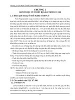
To derive a simple quantitative expression for abrasive wear, we assume a conical asperity on
the hard surface (Fig. 21.7). Then the volume of wear removed is given as follows [Rabinowicz,
1965]:
V = kW x tan µ=H (21:7)
where
tan µ
is a weighted average of the tan µ values of all the individual cones and k is a factor
that includes the geometry of the asperities and the probability that a given asperity cuts (removes)
rather than ploughs. Thus, the roughness effect on the volume of wear is very
distinct.
Materials
Wearing Surface Counter Surface Vickers Coefficient of Wear Coefficient
Table 21.3 Coefficient of Friction and Wear Coefficients for Various Materials in the Unlubricated
Sliding
© 1998 by CRC PRESS LLC
Fatigue Wear
Subsurface and surface fatigue are observed during repeated rolling and sliding, respectively. For
pure rolling condition the maximum shear stress responsible for nucleation of cracks occurs some
distance below the surface, and its location moves towards the surface with an application of the
friction force at the interface. The repeated loading and unloading cycles to which the materials are
exposed may induce the formation of subsurface or surface cracks, which eventually, after a
critical number of cycles, will result in the breakup of the surface with the formation of large
fragments, leaving large pits in the surface. Prior to this critical point, negligible wear takes place,
which is in marked contrast to the wear caused by adhesive or abrasive mechanism, where wear
causes a gradual deterioration from the start of running. Therefore, the amount of material removed
by fatigue wear is not a useful parameter. Much more relevant is the useful life in terms of the
number of revolutions or time before fatigue failure occurs. Time to fatigue failure is dependent on
the amplitude of the reversed shear stresses, the interface lubrication conditions, and the fatigue
properties of the rolling materials.
Impact Wear
Two broad types of wear phenomena belong in the category of impact wear: erosive and
percussive wear. Erosion can occur by jets and streams of solid particles, liquid droplets, and
implosion of bubbles formed in the fluid. Percussion occurs from repetitive solid body impacts.
Erosive wear by impingement of solid particles is a form of abrasion that is generally treated rather
differently because the contact stress arises from the kinetic energy of a particle flowing in an air or
liquid stream as it encounters a surface. The particle velocity and impact angle combined with the
size of the abrasive give a measure of the kinetic energy of the erosive stream. The volume of wear
is proportional to the kinetic energy of the impinging particles, that is, to the square of the velocity.
Figure 21.7
Abrasive wear model in which a cone removes material from a surface. (Source:
Rabinowicz, E. 1965. Friction and Wear of Materials. John Wiley & Sons, New York. With
permission.)
© 1998 by CRC PRESS LLC
Wear rate dependence on the impact angle differs between ductile and brittle materials. [Bitter,
1963].
When small drops of liquid strike the surface of a solid at high speeds (as low as 300 m/s), very
high pressures are experienced, exceeding the yield strength of most materials. Thus, plastic
deformation or fracture can result from a single impact, and repeated impact leads to pitting and
erosive wear. Caviation erosion arises when a solid and fluid are in relative motion and bubbles
formed in the fluid become unstable and implode against the surface of the solid. Damage by this
process is found in such components as ships' propellers and centrifugal
pumps.
Percussion is a repetitive solid body impact, such as experienced by print hammers in high-speed
electromechanical applications and high asperities of the surfaces in a gas bearing (e.g.,
head-medium interface in magnetic storage systems). In most practical machine applications the
impact is associated with sliding; that is, the relative approach of the contacting surfaces has both
normal and tangential components known as compound impact [Engel, 1976].
Corrosive Wear
Corrosive wear occurs when sliding takes place in a corrosive environment. In the absence of
sliding, the products of the corrosion (e.g., oxides) would form a film typically less than a
micrometer thick on the surfaces, which would tend to slow down or even arrest the corrosion, but
the sliding action wears the film away, so that the corrosive attack can continue. Thus, corrosive
wear requires both corrosion and rubbing. Machineries operating in an industrial environment or
near the coast generally corrode more rapidly than those operating in a clean environment.
Corrosion can occur because of chemical or electrochemical interaction of the interface with the
environment. Chemical corrosion occurs in a highly corrosive environment and in high
temperature and high humidity environments. Electrochemical corrosion is a chemical reaction
accompanied by the passage of an electric current, and for this to occur a potential difference must
exist between two regions.
Electrical Arc− Induced Wear
When a high potential is present over a thin air film in a sliding process, a dielectric breakdown
results that leads to arcing. During arcing, a relatively high-power density (on the order of 1
kW/
mm
2
) occurs over a very short period of time (on the order of 100
¹s
). The heat affected zone
is usually very shallow (on the order of 50
¹m
). Heating is caused by the Joule effect due to the
high power density and by ion bombardment from the plasma above the surface. This heating
results in considerable melting, corrosion, hardness changes, other phase changes, and even the
direct ablation of material. Arcing causes large craters, and any sliding or oscillation after an arc
either shears or fractures the lips, leading to abrasion, corrosion, surface fatigue, and fretting.
Arcing can thus initiate several modes of wear, resulting in catastrophic failures in electrical
machinery [Bhushan and Davis, 1983].
© 1998 by CRC PRESS LLC
Fretting occurs where low-amplitude vibratory motion takes place between two metal surfaces
loaded together [Anonymous, 1955]. This is a common occurrence because most machinery is
subjected to vibration, both in transit and in operation. Examples of vulnerable components are
shrink fits, bolted parts, and splines. Basically, fretting is a form of adhesive or abrasive wear
where the normal load causes adhesion between asperities and vibrations cause ruptures, resulting
in wear debris. Most commonly, fretting is combined with corrosion, in which case the wear mode
is known as fretting corrosion.
21.5 Lubrication
Sliding between clean solid surfaces is generally characterized by a high coefficient of friction and
severe wear due to the specific properties of the surfaces, such as low hardness, high surface
energy, reactivity, and mutual solubility. Clean surfaces readily adsorb traces of foreign
substances, such as organic compounds, from the environment. The newly formed surfaces
generally have a much lower coefficient of friction and wear than the clean surfaces. The presence
of a layer of foreign material at an interface cannot be guaranteed during a sliding process;
therefore, lubricants are deliberately applied to produce low friction and wear. The term
lubrication is applied to two different situations: solid lubrication and fluid (liquid or gaseous)
film lubrication.
Solid Lubrication
A solid lubricant is any material used in bulk or as a powder or a thin, solid film on a surface to
provide protection from damage during relative movement to reduce friction and wear. Solid
lubricants are used for applications in which any sliding contact occurs, for example, a bearing
operative at high loads and low speeds and a hydrodynamically lubricated bearing requiring
start/stop operations. The term solid lubricants embraces a wide range of materials that provide
low friction and wear [Bhushan and Gupta, 1991]. Hard materials are also used for low wear under
extreme operating conditions.
Fluid Film Lubrication
A regime of lubrication in which a thick fluid film is maintained between two sliding surfaces by
an external pumping agency is called hydrostatic lubrication.
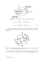
A summary of the lubrication regimes observed in fluid (liquid or gas) lubrication without an
external pumping agency (self-acting) can be found in the familiar Stribeck curve in Fig. 21.8. This
plot for a hypothetical fluid-lubricated bearing system presents the coefficient of friction as a
function of the product of viscosity
(´) and rotational speed (N ) divided by the normal pressure
(p): The curve has a minimum, which immediately suggests that more than one lubrication
mechanism is involved. The regimes of lubrication are sometimes identified by a lubricant film
parameter
¤
equal to h=¾; which is mean film thickness divided by composite standard deviation
of surface roughnesses. Descriptions of different regimes of lubrication follow [Booser, 1984;
Bhushan, 1990].
Fretting and Fretting Corrosion
© 1998 by CRC PRESS LLC
Figure 21.8 Lubricant film parameter
(¤)
and coefficient of friction as a function of
´N=p
(Stribeck
curve) showing different lubrication regimes observed in fluid lubrication without an external pumping
agency. Schematics of interfaces operating in different lubrication regimes are also
shown.
© 1998 by CRC PRESS LLC
Hydrostatic Lubrication
Hydrostatic bearings support load on a thick film of fluid supplied from an external pressure
source
a pumpwhich feeds pressurized fluid to the film. For this reason, these bearings are
often called "externally pressurized." Hydrostatic bearings are designed for use with both
incompressible and compressible fluids. Since hydrostatic bearings do not require relative motion
of the bearing surfaces to build up the load-supporting pressures as necessary in hydrodynamic
bearings, hydrostatic bearings are used in applications with little or no relative motion between the
surfaces. Hydrostatic bearings may also be required in applications where, for one reason or
another, touching or rubbing of the bearing surfaces cannot be permitted at startup and shutdown.
In addition, hydrostatic bearings provide high stiffness. Hydrostatic bearings, however, have the
disadvantage of requiring high-pressure pumps and equipment for fluid cleaning, which adds to
space and cost.
Hydrodynamic Lubrication
Hydrodynamic (HD) lubrication is sometimes called fluid-film or thick-film lubrication. As a
bearing with convergent shape in the direction of motion starts to spin (slide in the longitudinal
direction) from rest, a thin layer of fluid is pulled through because of viscous entrainment and is
then compressed between the bearing surfaces, creating a sufficient (hydrodynamic) pressure to
support the load without any external pumping agency. This is the principle of hydrodynamic
lubrication, a mechanism that is essential to the efficient functioning of the self-acting journal and
thrust bearings widely used in modern industry. A high load capacity can be achieved in the
bearings that operate at high speeds and low loads in the presence of fluids of high
viscosity.
Fluid film can also be generated only by a reciprocating or oscillating motion in the normal
direction (squeeze), which may be fixed or variable in magnitude (transient or steady state). This
load-carrying phenomenon arises from the fact that a viscous fluid cannot be instantaneously
squeezed out from the interface with two surfaces that are approaching each other. It takes time for
these surfaces to meet, and during that interval
because of the fluid's resistance to extrusiona
pressure is built up and the load is actually supported by the fluid film. When the load is relieved or
becomes reversed, the fluid is sucked in and the fluid film often can recover its thickness in time
for the next application. The squeeze phenomenon controls the buildup of a water film under the
tires of automobiles and airplanes on wet roadways or landing strips (commonly known as
hydroplaning) that have virtually no relative sliding motion.
HD lubrication is often referred to as the ideal lubricated contact condition because the
lubricating films are normally many times thicker (typically 5
−500
¹m
) than the height of the
irregularities on the bearing surface, and solid contacts do not occur. The coefficient of friction in
the HD regime can be as small as 0.001 (Fig. 21.8). The friction increases slightly with the sliding
speed because of viscous drag. The behavior of the contact is governed by the bulk physical
properties of the lubricant, notable viscosity, and the frictional characteristics arise purely from the
shearing of the viscous lubricant.
© 1998 by CRC PRESS LLC
Elastohydrodynamic (EHD) lubrication is a subset of HD lubrication in which the elastic
deformation of the bounding solids plays a significant role in the HD lubrication process. The film
thickness in EHD lubrication is thinner (typically 0.5
−2.5
¹m
) than that in HD lubrication (Fig.
21.8), and the load is still primarily supported by the EHD film. In isolated areas, asperities may
actually touch. Therefore, in liquid lubricated systems, boundary lubricants that provide boundary
films on the surfaces for protection against any solid-solid contact are used. Bearings with heavily
loaded contacts fail primarily by a fatigue mode that may be significantly affected by the lubricant.
EHD lubrication is most readily induced in heavily loaded contacts (such as machine elements of
low geometrical conformity), where loads act over relatively small contact areas (on the order of
one-thousandth of journal bearing), such as the point contacts of ball bearings and the line contacts
of roller bearings and gear teeth. EHD phenomena also occur in some low elastic modulus contacts
of high geometrical conformity, such as seals and conventional journal and thrust bearings with
soft liners.
Mixed Lubrication
The transition between the hydrodynamic/elastohydrodynamic and boundary lubrication regimes
constitutes a gray area known as mixed lubrication, in which two lubrication mechanisms may be
functioning. There may be more frequent solid contacts, but at least a portion of the bearing
surface remains supported by a partial hydrodynamic film (Fig. 21.8). The solid contacts, if
between unprotected virgin metal surfaces, could lead to a cycle of adhesion, metal transfer, wear
particle formation, and snowballing into seizure. However, in liquid lubricated bearings, the physi-
or chemisorbed or chemically reacted films (boundary lubrication) prevent adhesion during most
asperity encounters. The mixed regime is also sometimes referred to as quasihydrodynamic, partial
fluid, or thin-film (typically 0.5
− 2.5
¹m
) lubrication.
Boundary Lubrication
As the load increases, speed decreases or the fluid viscosity decreases in the Stribeck curve shown
in Fig. 21.8; the coefficient of friction can increase sharply and approach high levels (about 0.2 or
much higher). In this region it is customary to speak of boundary lubrication. This condition can
also occur in a starved contact. Boundary lubrication is that condition in which the solid surfaces
are so close together that surface interaction between monomolecular or multimolecular films of
lubricants (liquids or gases) and the solids dominate the contact. (This phenomenon does not apply
to solid lubricants.) The concept is represented in Fig. 21.8, which shows a microscopic cross
section of films on two surfaces and areas of asperity contact. In the absence of boundary
lubricants and gases (no oxide films), friction may become very high
(>1):
21.6 Micro/nanotribology
AFM/FFMs are commonly used to study engineering surfaces on micro- to nanoscales. These
instruments measure the normal and friction forces between a sharp tip (with a tip radius of
30
−100 nm) and an engineering surface. Measurements can be made at loads as low as less than 1
nN and at scan rates up to about 120 Hz. A sharp AFM/ FFM tip sliding on a surface simulates a
single asperity contact. FFMs are used to measure coefficient of friction on micro- to nanoscales
Elastohydrodynamic Lubrication
© 1998 by CRC PRESS LLC
and AFMs are used for studies of surface topography, scratching/wear and boundary lubrication,
mechanical property measurements, and nanofabrication/nanomachining [Bhushan and Ruan,
1994; Bhushan et al., 1994; Bhushan and Koinkar, 1994a,b; Ruan and Bhushan, 1994; Bhushan,
1995; Bhushan et al., 1995]. For surface roughness, friction force, nanoscratching and nanowear
measurements, a microfabricated square pyramidal
Si
3
N
4
tip with a tip radius of about 30 nm is
generally used at loads ranging from 10 to 150 nN. For microscratching, microwear,
nanoindentation hardness measurements, and nanofabrication, a three-sided pyramidal
single-crystal natural diamond tip with a tip radius of about 100 nm is used at relatively high loads
ranging from 10
¹N
to 150
¹
N. Friction and wear on micro- and nanoscales are found to be
generally smaller compared to that at macroscales. For an example of comparison of coefficients of
friction at macro- and microscales see Table 21.4.
Table 21.4
Surface Roughness and Micro- and Macroscale Coefficients of Friction of Various
Samples
Macroscale Coefficient of Friction versus
Alumina Ball
2
Material RMS Roughness,nm Microscale
Coefficient of
Friction versus
Si
3
N
4
Tip
1
0.1 N 1 N
Si (111) 0.11 0.03 0.18 0.60
C
+
-
implanted Si 0.33 0.02 0.18 0.18
1
Si
3
N
4
tip (with about 50 nm radius) in the load range of 10−150 nN (1.5−3.8 GPa), a scanning speed of 4 ¹m/s
and scan area of
1 ¹m £ 1 ¹m
.
2
Alumina ball with 3-mm radius at normal loads of 0.1 and 1 N (0.23 and 0.50 GPa) and average sliding speed of
0.8 mm/s.
Defining Terms
Friction: The resistance to motion whenever one solid slides over another.
Lubrication: Materials applied to the interface to produce low friction and wear in either of two
situations
solid lubrication or fluid (liquid or gaseous) film
lubrication.
Micro/nanotribology: The discipline concerned with experimental and theoretical investigations
of processes (ranging from atomic and molecular scales to microscales) occurring during
adhesion, friction, wear, and lubrication at sliding surfaces.
Tribology: The science and technology of two interacting surfaces in relative motion and of
related subjects and practices.
Wear: The removal of material from one or both solid surfaces in a sliding, rolling, or impact
motion relative to one another.
© 1998 by CRC PRESS LLC
Anonymous. 1955. Fretting and fretting corrosion. Lubrication. 41:85−96.
Archard, J. F. 1953. Contact and rubbing of flat surfaces. J. Appl. Phys. 24:981
−988.
Archard, J. F. 1980. Wear theory and mechanisms. Wear Control Handbook, ed. M. B. Peterson
and W. O. Winer, pp. 35
−80. ASME, New York.
Avallone, E. A. and Baumeister, T., III. 1987. Marks' Standard Handbook for Mechanical
Engineers, 9th ed. McGraw-Hill, New York.
Benzing, R., Goldblatt, I., Hopkins, V., Jamison, W., Mecklenburg, K., and Peterson, M. 1976.
Friction and Wear Devices, 2nd ed. ASLE, Park Ridge, IL.
Bhushan, B. 1984. Analysis of the real area of contact between a polymeric magnetic medium and
a rigid surface. ASME J. Lub. Tech. 106:26
−34.
Bhushan, B. 1990. Tribology and Mechanics of Magnetic Storage Devices. Springer-Verlag, New
York.
Bhushan, B. 1992. Mechanics and Reliability of Flexible Magnetic Media. Springer-Verlag, New
York.
Bhushan, B. 1995. Handbook of Micro/Nanotribology. CRC Press, Boca Raton, FL.
Bhushan, B. and Davis, R. E. 1983. Surface analysis study of electrical-arc-induced wear. Thin
Solid Films. 108:135
−156.
Bhushan, B., Davis, R. E., and Gordon, M. 1985a. Metallurgical re-examination of wear modes. I:
Erosive, electrical arcing and fretting. Thin Solid Films. 123:93
−112.
Bhushan, B., Davis, R. E., and Kolar, H. R. 1985b. Metallurgical re-examination of wear modes.
II: Adhesive and abrasive. Thin Solid Films. 123:113
−126.
Bhushan, B. and Gupta, B. K. 1991. Handbook of Tribology: Materials, Coatings, and Surface
Treatments. McGraw-Hill, New York.
Bhushan, B., Israelachvili, J. N., and Landman, U. 1995. Nanotribology: Friction, Wear and
Lubrication at the Atomic Scale. Nature. 374:607
−616.
Bhushan, B. and Koinkar, V. N. 1994a. Tribological studies of silicon for magnetic recording
applications. J. Appl. Phys. 75:5741
−5746.
Bhushan, B. and Koinkar, V. N. 1994b. Nanoindentation hardness measurements using atomic
force microscopy. Appl. Phys. Lett. 64:1653
−1655.
Bhushan, B., Koinkar, V. N., and Ruan, J. 1994. Microtribology of magnetic media. Proc. Inst.
Mech. Eng., Part J: J. Eng. Tribol. 208:17
−29.
Bhushan, B. and Ruan, J. 1994. Atomic-scale friction measurements using friction force
microscopy: Part II
Application to magnetic media. ASME J. Tribology. 116:389−396.
Binnig, G., Quate, C. F., and Gerber, C. 1986. Atomic force microscope. Phys. Rev. Lett.
56:930
−933.
Binnig, G., Rohrer, H., Gerber, C., and Weibel, E. 1982. Surface studies by scanning tunnelling
microscopy. Phys. Rev. Lett. 49:57
−61.
Bitter, J. G. A. 1963. A study of erosion phenomena. Wear. 6:5
−21; 169−190.
Booser, E. R. 1984. CRC Handbook of Lubrication, vol. 2. CRC Press, Boca Raton, FL.
Bowden, F. P. and Tabor, D. 1950. The Friction and Lubrication of Solids, vols. I and II.
Clarendon Press, Oxford.
Davidson, C. S. C. 1957. Bearing since the stone age.
Engineering.
183:2
−
5.
References
© 1998 by CRC PRESS LLC
Dowson, D. 1979. History of Tribology. Longman, London.
Engel, P. A. 1976. Impact Wear of Materials. Elsevier, Amsterdam.
Fuller, D. D. 1984. Theory and Practice of Lubrication for Engineers, 2nd ed. John Wiley & Sons,
New York.
Georges, J. M., Millot, S., Loubet, J. L., and Tonck, A. 1993. Drainage of thin liquid films
between relatively smooth surfaces. J. Chem. Phys. 98:7345
−7360.
Georges, J. M., Tonck, A., and Mazuyer, D. 1994. Interfacial friction of wetted monolayers. Wear.
175:59
−62.
Greenwood, J. A. and Williamson, J. B. P. 1966. Contact of nominally flat surfaces. Proc. R. Soc.
Lond. A295:300
−319.
Holm, R. 1946. Electrical Contact. Springer-Verlag, New York.
Israelachvili, J. N. and Adams, G. E. 1978. Measurement of friction between two mica surfaces in
aqueous electrolyte solutions in the range 0
−100 nm. Chem. Soc. J., Faraday Trans. I.
74:975
−1001.
Jost, P. 1966. Lubrication (Tribology)
A Report on the Present Position and Industry's
Needs. Department of Education and Science, H.M. Stationary Office,
London.
Jost, P. 1976. Economic impact of tribology. Proc. Mechanical Failures Prevention Group. NBS
Special Pub. 423, Gaithersburg, MD.
Klein, J. 1980. Forces between mica surfaces bearing layers of adsorbed polystyrene in
Cyclohexane. Nature. 288:248
−250.
Layard, A. G. 1853. Discoveries in the Ruins of Nineveh and Babylon, I and II. John Murray,
Albemarle Street, London.
Mate, C. M., McClelland, G. M., Erlandsson, R., and Chiang, S. 1987. Atomic-scale friction of a
tungsten tip on a graphite surface. Phys. Rev. Lett. 59:1942
− 1945.
Parish, W. F. 1935. Three thousand years of progress in the development of machinery and
lubricants for the hand crafts. Mill and Factory. Vols. 16 and 17.
Peachey, J., Van Alsten, J., and Granick, S. 1991. Design of an apparatus to measure the shear
response of ultrathin liquid films. Rev. Sci. Instrum. 62:463
−473.
Petroff, N. P. 1883. Friction in machines and the effects of the lubricant. Eng. J. (in Russian; St.
Petersburg) 71
−140, 228−279, 377−436, 535−564.
Rabinowicz, E. 1965. Friction and Wear of Materials. John Wiley & Sons, New York.
Rabinowicz, E. 1980. Wear coefficients
metals. Wear Control Handbook, ed. M. B. Peterson and
W. O. Winer, pp. 475
−506. ASME, New York.
Reynolds, O. O. 1886. On the theory of lubrication and its application to Mr. Beauchamp Tower's
experiments. Phil. Trans. R. Soc. (Lond.) 177:157
−234.
Ruan, J. and Bhushan, B. 1994. Atomic-scale and microscale friction of graphite and diamond
using friction force microscopy. J. Appl. Phys. 76:5022
−5035.
Tabor, D. and Winterton, R. H. S. 1969. The direct measurement of normal and retarded van der
Waals forces. Proc. R. Soc. Lond. A312:435
−450.
Tonck, A., Georges, J. M., and Loubet, J. L. 1988. Measurements of intermolecular forces and the
rheology of dodecane between alumina surfaces. J. Colloid Interf. Sci. 126:1540
−1563.
© 1998 by CRC PRESS LLC
Tower, B. 1884. Report on friction experiments. Proc. Inst. Mech. Eng. 632.
Further Information
Major conferences:
ASME/STLE Tribology Conference held every October in the U.S.
Leeds-Lyon Symposium on Tribology held every year at Leeds, U.K., or Lyon, France
(alternating locations).
International Symposium on Advances in Information Storage and Processing Systems held
annually at ASME International Congress and Exposition in November/December in the
U.S.
International Conference on Wear of Materials held every two years; next one to be held in
1995.
Eurotrib held every four years; next one to be held in 1997.
Societies:
Information Storage and Processing Systems Division, The American Society of Mechanical
Engineers, New York.
Tribology Division, The American Society of Mechanical Engineers, New
York.
Institution of Mechanical Engineers, London, U.K.
Society of Tribologists and Lubrication Engineers, Park Ridge, IL.
© 1998 by CRC PRESS LLC
Pennock, G. R. “Machine Elements”
The Engineering Handbook.
Ed. Richard C. Dorf
Boca Raton: CRC Press LLC, 2000
© 1998 by CRC PRESS LLC
22
Machine Elements
22.1 Threaded Fasteners
22.2 Clutches and Brakes
Rim-Type Clutches and Brakes • Axial-Type Clutches and Brakes • Disk Clutches and Brakes • Cone
Clutches and Brakes • Positive-Contact Clutches
Gordon R. Pennock
Purdue University
Section 22.1 presents a discussion of threaded fasteners, namely, the nut and bolt, the machine
screw, the cap screw, and the stud. Equations are presented for the spring stiffness of the portion of
a bolt, or a cap screw, within the clamped zone, which generally consists of the unthreaded shank
portion and the threaded portion. Equations for the resultant bolt load and the resultant load on the
members are also included in the discussion. The section concludes with a relation that provides an
estimate of the torque that is required to produce a given preload. Section 22.2 presents a
discussion of clutches and brakes and the important features of these machine elements. Various
types of frictional-contact clutches and brakes are included in the discussion, namely, the radial,
axial, disk, and cone types. Information on positive-contact clutches and brakes is also provided.
The section includes energy considerations, equations for the temperature-rise, and the
characteristics of a friction material.
22.1 Threaded Fasteners
The bolted joint with hardened steel washers is a common solution when a connection is required
that can be easily disassembled (without destructive methods) and is strong enough to resist
external tensile loads and shear loads. The clamping load, which is obtained by twisting the nut
until the bolt is close to the elastic limit, stretches or elongates the bolt. This bolt tension will
remain as the clamping force, or preload, providing the nut does not loosen. The preload induces
compression in the members, which are clamped together, and exists in the connection after the nut
has been properly tightened, even if there is no external load. Care must be taken to ensure that a
bolted joint is properly designed and assembled [Blake, 1986]. When tightening the connection,
the bolt head should be held stationary and the nut twisted. This procedure will ensure that the bolt
shank will not experience the thread-friction torque. During the tightening process, the first thread
on the nut tends to carry the entire load. However, yielding occurs with some strengthening due to
the cold work that takes place, and the load is eventually distributed over about three nut threads.
For this reason, it is recommended that nuts should not be reused; in fact, it can be dangerous if
© 1998 by CRC PRESS LLC
this practice is adopted [Shigley and Mischke, 1989].
There are several styles of hexagonal nut, namely, (1) the general hexagonal nut, (2) the
washer-faced regular nut, (3) the regular nut chamfered on both sides, (4) the jam nut with washer
face, and (5) the jam nut chamfered on both sides. Flat nuts only have a chamfered top [Shigley
and Mischke, 1986]. The material of the nut must be selected carefully to match that of the bolt.
Carbon steel nuts are usually made to conform to ASTM A563 Grade A specifications or to SAE
Grade 2. A variety of machine screw head styles also exist; they include (1) fillister head, (2) flat
head, (3) round head, (4) oval head, (5) truss head, (6) binding head, and (7) hexagonal head
(trimmed and upset). There are also many kinds of locknuts, which have been designed to prevent
a nut from loosening in service. Spring and lock washers placed beneath an ordinary nut are also
common devices to prevent loosening.
Another tension-loaded connection uses cap screws threaded into one of the members. Cap
screws can be used in the same applications as nuts and bolts and also in situations where one of
the clamped members is threaded. The common head styles of the cap screw include (1) hexagonal
head, (2) fillister head, (3) flat head, and (4) hexagonal socket head. The head of a hexagon-head
cap screw is slightly thinner than that of a hexagon-head bolt. An alternative to the cap screw is the
stud, which is a rod threaded on both ends. Studs should be screwed into the lower member first,
then the top member should be positioned and fastened down with hardened steel washers and
nuts. The studs are regarded as permanent and the joint should be disassembled by removing only
the nuts and washers. In this way, the threaded part of the lower member is not damaged by
reusing the threads.
The grip of a connection is the total thickness of the clamped material [Shigley and Mischke,
1989]. In the bolted joint the grip is the sum of the thicknesses of both the members and the
washers. In a stud connection the grip is the thickness of the top member plus that of the washer.
The spring stiffness, or spring rate, of an elastic member such as a bolt is the ratio of the force
applied to the member and the deflection caused by that force. The spring stiffness of the portion
of a bolt, or cap screw, within the clamped zone generally consists of two parts, namely, (1) that of
the threaded portion, and (2) that of the unthreaded shank portion. Therefore, the stiffness of a bolt
is equivalent to the stiffness of two springs in series:
1
k
b
=
1
k
T
+
1
k
d
or k
b
=
k
T
k
d
k
T
+ k
d
(22:1)
The spring stiffnesses of the threaded and unthreaded portions of the bolt in the clamped zone,
respectively, are
k
T
=
A
t
E
L
T
and k
d
=
A
d
E
L
d
(22:2)
where
A
t
is the tensile-stress area,
L
T
is the length of the threaded portion in the grip,
A
d
is the
major-diameter area of the fastener,
L
d
is the length of the unthreaded portion in the grip, and E is
the modulus of elasticity. Substituting Eq. (22.2) into Eq. (22.1), the estimated effective stiffness of
the bolt (or cap screw) in the clamped zone can be expressed as
© 1998 by CRC PRESS LLC
k
b
=
A
t
A
d
E
A
t
L
d
+ A
d
L
T
(22:3)
For short fasteners the unthreaded area is small and so the first of the expressions in Eq. (22.2)
can be used to evaluate
k
b
. In the case of long fasteners the threaded area is relatively small, so the
second expression in Eq. (22.2) can be used to evaluate the effective stiffness of the bolt.
Expressions can also be obtained for the stiffness of the members in the clamped zone [Juvinall,
1983]. Both the stiffness of the fastener and the stiffness of the members in the clamped zone must
be known in order to understand what happens when the connection is subjected to an external
tensile load. There may of course be more than two members included in the grip of the fastener.
Taken together the members act like compressive springs in series, and hence the total spring
stiffness of the members is
1
k
m
=
1
k
1
+
1
k
2
+
1
k
3
+ ¢ ¢ ¢ (22:4)
If one of the members is a soft gasket, its stiffness relative to the other members is usually so
small that for all practical purposes the other members can be neglected and only the gasket
stiffness need be considered. If there is no gasket, the stiffness of the members is difficult to obtain,
except by experimentation, because the compression spreads out between the bolt head and the nut
and hence the area is not uniform. There are, however, some cases in which this area can be
determined. Ultrasonic techniques have been used to determine the pressure distribution at the
member interface in a bolt-flange assembly [Ito et al., 1977]. The results show that the pressure
stays high out to about 1.5 times the bolt radius and then falls off farther away from the bolt.
Rotsher's pressure-cone method has been suggested for stiffness calculations with a variable cone
angle. This method is quite complicated and a simpler approach is to use a fixed cone angle [Little,
1967].
Consider what happens when an external tensile load is applied to a bolted connection.
Assuming that the preload has been correctly applied (by tightening the nut before the external
tensile load is applied), the tensile load causes the connection to stretch through some distance.
This elongation can be related to the stiffness of the bolts, or the members, by the equation
± =
P
b
k
b
=
P
m
k
m
or P
b
=
k
b
k
m
P
m
(22:5)
where
P
b
is the portion of the external tensile load P taken by the bolt and
P
m
is the portion of P
taken by the members. Since the external tensile load P is equal to
P
b
+ P
m
,
P
b
=
µ
k
b
k
b
+ k
m
P and P
m
=
µ
k
m
k
b
+ k
m
P (22:6)
The resultant bolt load is
F
b
= P
b
+ F
i
and the resultant load on the members is
F
m
= P
m
¡ F
i
,
where
F
i
is the preload. Therefore, the resultant bolt load can be written as
© 1998 by CRC PRESS LLC
F
b
=
µ
k
b
k
b
+ k
m
P + F
i
; F
m
< 0 (22:7)
and the resultant load on the members can be written as
F
m
=
µ
k
m
k
b
+ k
m
P ¡ F
i
; F
m
< 0 (22:8)
Equations (22.7) and (22.8) are only valid for the case when some clamping load remains in the
members, which is indicated by the qualifier in the two equations. Making the grip longer causes
the members to take an even greater percentage of the external load. If the external load is large
enough to completely remove the compression, then the members will separate and the entire load
will be carried by the bolts.
Since it is desirable to have a high preload in important bolted connections, methods of ensuring
that the preload is actually developed when the parts are assembled must be considered. If the
overall length of the bolt,
L
b
, can be measured (say with a micrometer) when the parts are
assembled, then the bolt elongation due to the preload
F
i
can be computed from the relation
± =
F
i
L
b
AE
(22:9)
where A is the cross-sectional area of the bolt. The nut can then be tightened until the bolt
elongates through the distance
±, which ensures that the desired preload has been obtained. In
many cases, however, it is not practical or possible to measure the bolt elongation. For example,
the elongation of a screw cannot be measured if the threaded end is in a blind hole. In such cases
the wrench torque that is required to develop the specified preload must be estimated. Torque
wrenching, pneumatic-impact wrenching, or the turn-of-the-nut method can be used [Blake and
Kurtz, 1965]. The torque wrench has a built-in dial that indicates the proper torque. With
pneumatic-impact wrenching, the air pressure is adjusted so that the wrench stalls when the proper
torque is obtained or, in some cases, the air shuts off automatically at the desired torque.
The snug-tight condition is defined as the tightness attained by a few impacts of an impact
wrench or the full effort of a person using an ordinary wrench. When the snug-tight condition is
attained, all additional turning develops useful tension in the bolt. The turn-of-the-nut method
requires that fractional number of turns necessary to develop the required preload from the
snug-tight condition be computed. For example, for heavy hexagon structural bolts, the
turn-of-the-nut specification requires that under optimum conditions the nut should be turned a
minimum of
180
±
from the snug-tight condition. A good estimate of the torque required to produce
a given preload
F
i
can be obtained from the relation [Shigley and Mischke, 1989]
T =
F
i
d
m
2
µ
L + ¼¹d
m
sec ®
¼d
m
¡ ¹L sec ®
+
F
i
¹
c
d
c
2
(22:10)
© 1998 by CRC PRESS LLC
where d
m
is the mean diameter of the bolt, L is the lead of the thread,
®
is half the thread angle,
¹
c
is the coefficient of thread friction,
¹
c
is the coefficient of collar friction, and d
c
is the mean collar
diameter. The coefficients of friction depend upon the surface smoothness, the accuracy, and the
degree of lubrication. Although these items may vary considerably, it is interesting to note that on
the average both
¹
and
¹
c
are approximately 0.15.
22.2 Clutches and Brakes
A clutch is a coupling that connects two shafts rotating at different speeds and brings the output
shaft smoothly and gradually to the same speed as the input shaft. Clutches and brakes are machine
elements associated with rotation and have in common the function of storing or transferring
rotating energy [Remling, 1983]. When the rotating members are caused to stop by means of a
brake, the kinetic energy of rotation must be absorbed by the brake. In the same way, when the
members of a machine that are initially at rest are brought up to speed, slipping must occur in the
clutch until the driven members have the same speed as the driver. Kinetic energy is absorbed
during slippage of either a clutch or a brake, and this energy appears in the form of heat. The
important features in the performance of these devices are (1) the actuating force, (2) the
transmitted torque, (3) the energy loss, and (4) the temperature rise. The torque that is transmitted
is related to the actuating force, the coefficient of friction, and the geometry of the device.
Essentially this is a problem in statics and can be studied separately for each geometric
configuration. The rise in temperature, however, can be studied without regard to the type of
device because the heat-dissipating surfaces are the geometry of interest. An approximate guide to
the rise in temperature in a drum brake is the horsepower per square inch [Spotts, 1985].
The torque capacity of a clutch or brake depends upon the coefficient of friction of the material
and a safe normal pressure. The character of the load may be such, however, that if this torque
value is permitted, the clutch or brake may be destroyed by the generated heat. Therefore, the
capacity of a clutch is limited by two factors: (a) the characteristics of the material, and (b) the
ability of the clutch to dissipate the frictional heat. The temperature rise of a clutch or brake
assembly can be approximated by the relation
¢T =
H
CW
(22:11)
where
¢T
is in
±
F
, H is the heat generated in Btu, C is the specific heat in Btu/(lbm
±
F ), and W is
the mass of the clutch or brake assembly in
lbm . If SI units are used, then
¢T =
E
Cm
(22:12)
where
¢T
is in
±
C
, E is the total energy dissipated during the clutching operation or the braking
cycle in J, C is in J/kg
±
C
, and m is the mass of the clutch or brake assembly in kg. Equation
(22.11) or (22.12) can be used to explain what happens when a clutch or a brake is operated.
However, there are so many variables involved that it is most unlikely that the analytical results
© 1998 by CRC PRESS LLC
would approximate experimental results. For this reason such analyses are only useful, for
repetitive cycling, in pinpointing the design parameters that have the greatest effect on
performance.
The friction material of a clutch or brake should have the following characteristics, to a degree
that is dependent upon the severity of the service: (a) a high and uniform coefficient of friction, (b)
imperviousness to environmental conditions, such as moisture, (c) the ability to withstand high
temperatures, as well as a good heat conductivity, (d) good resiliency, and (e) high resistance to
wear, scoring, and galling. The manufacture of friction materials is a highly specialized process,
and the selection of a friction material for a specific application requires some expertise. Selection
involves a consideration of all the characteristics of a friction material as well as the standard sizes
that are available. The woven-cotton lining is produced as a fabric belt, which is impregnated with
resins and polymerized. It is mostly used in heavy machinery and can be purchased in rolls up to
50 feet in length. The thicknesses that are available range from 0.125 to 1 in. and the width may be
up to 12 in. A woven-asbestos lining is similar in construction to the cotton lining and may also
contain metal particles. It is not quite as flexible as the cotton lining and comes in a smaller range
of sizes. The woven-asbestos lining is also used as a brake material in heavy machinery.
Molded-asbestos linings contain asbestos fiber and friction modifiers; a thermoset polymer is
used, with heat, to form a rigid or a semirigid molding. The principal use is in drum brakes.
Molded-asbestos pads are similar to molded linings but have no flexibility; they are used for both
clutches and brakes. Sintered-metal pads are made of a mixture of copper and/or iron particles with
friction modifiers, molded under high pressure and then heated to a high temperature to fuse the
material. These pads are used in both brakes and clutches for heavy-duty applications. Cermet pads
are similar to the sintered-metal pads and have a substantial ceramic content. Typical brake linings
may consist of a mixture of asbestos fibers to provide strength and ability to withstand high
temperatures; various friction particles to obtain a degree of wear resistance and higher coefficient
of friction; and bonding materials. Some clutch friction materials may be run wet by allowing them
to dip in oil or to be sprayed by oil. This reduces the coefficient of friction, but more heat can be
transferred and higher pressure can be permitted.
The two most common methods of coupling are the frictional-contact clutch and the
positive-contact clutch. Other methods include the overrunning or freewheeling clutch, the
magnetic clutch, and the fluid coupling. In general, the types of frictional-contact clutches and
brakes can be classified as rim type or axial type [Marks, 1987]. The analysis of all types of
frictional-clutches and brakes follows the same general procedure, namely, (a) determine the
pressure distribution on the frictional surfaces, (b) find a relation between the maximum pressure
and the pressure at any point, and (c) apply the conditions of static equilibrium to find the actuating
force, the torque transmitted, and the support reactions. The analysis is useful when the dimensions
are known and the characteristics of the friction material are specified. In design, however,
synthesis is of more interest than analysis. Here the aim is to select a set of dimensions that will
provide the best device within the limitations of the frictional material that is specified by the
designer [Proctor, 1961].
© 1998 by CRC PRESS LLC
The rim-type brake can be designed for self-energizing, that is, using friction to reduce the
actuating force. Self-energization is important in reducing the required braking effort; however, it
also has a disadvantage. When rim-type brakes are used as vehicle brakes, a small change in the
coefficient of friction will cause a large change in the pedal force required for braking. For
example, it is not unusual for a 30% reduction in the coefficient of friction (due to a temperature
change or moisture) to result in a 50% change in the pedal force required to obtain the same
braking torque that was possible prior to the change.
The rim types may have internal expanding shoes or external contracting shoes. An internal shoe
clutch consists essentially of three elements: (1) a mating frictional surface, (2) a means of
transmitting the torque to and from the surfaces, and (3) an actuating mechanism. Depending upon
the operating mechanism, such clutches can be further classified as expanding-ring, centrifugal,
magnetic, hydraulic, or pneumatic. The expanding-ring clutch benefits from centrifugal effects,
transmits high torque even at low speeds, and requires both positive engagement and ample release
force. This type of clutch is often used in textile machinery, excavators, and machine tools in
which the clutch may be located within the driving pulley. The centrifugal clutch is mostly used for
automatic operation. If no spring is present, the torque transmitted is proportional to the square of
the speed [Beach, 1962]. This is particularly useful for electric motor drives in which, during
starting, the driven machine comes up to speed without shock. Springs can be used to prevent
engagement until a certain motor speed has been reached, but some shock may occur. Magnetic
clutches are particularly useful for automatic and remote-control systems and are used in drives
subject to complex load cycles. Hydraulic and pneumatic clutches are useful in drives having
complex loading cycles, in automatic machinery, and in manipulators. Here the fluid flow can be
controlled remotely using solenoid valves. These clutches are available as disk, cone, and
multiple-plate clutches.
In braking systems the internal-shoe or drum brake is used mostly for automotive applications.
The actuating force of the device is applied at the end of the shoe away from the pivot. Since the
shoe is usually long, the distribution of the normal forces cannot be assumed to be uniform. The
mechanical arrangement permits no pressure to be applied at the heel; therefore, frictional material
located at the heel contributes very little to the braking action. It is standard practice to omit the
friction material for a short distance away from the heel, which also eliminates interference. In
some designs the hinge pin is allowed to move to provide additional heel pressure. This gives the
effect of a floating shoe. A good design concentrates as much frictional material as possible in the
neighborhood of the point of maximum pressure. Typical assumptions made in an analysis of the
shoe include the following: (1) the pressure at any point on the shoe is proportional to the distance
from the hinge pin (zero at the heel); (2) the effect of centrifugal force is neglected (in the case of
brakes, the shoes are not rotating and no centrifugal force exists; in clutch design, the effect of this
force must be included in the equations of static equilibrium); (3) the shoe is rigid (in practice,
some deflection will occur depending upon the load, pressure, and stiffness of the shoe; therefore,
the resulting pressure distribution may be different from the assumed distribution); and (4) the
entire analysis is based upon a coefficient of friction that does not vary with pressure. Actually, the
coefficient may vary with a number of conditions, including temperature, wear, and the
environment.
For pivoted external shoe brakes and clutches, the operating mechanisms can be classified as
Rim-Type Clutches and Brakes
© 1998 by CRC PRESS LLC