Tài liệu Macine desigin databook P2 ppt
Bạn đang xem bản rút gọn của tài liệu. Xem và tải ngay bản đầy đủ của tài liệu tại đây (187.05 KB, 20 trang )
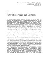
TABLE 1–13
Chemical composition and mechanical properties of alloy steels
ÃÃ
Percent Tensile strength,
st
0.2%
proof stress,
min,
sy
Minimum
elongation
(gauge length
¼ 5.65
ffiffiffiffiffi
a
Ã
p
)
a
,
Minimum
Izod impact
value Brinell
#
hardness
Limiting
ruling
section,
Designation C Si Mn Ni Cr Mo V/Al MPa kpsi MPa kpsi % J ft-lbf H
B
mm (in)
þ
20 C 15 (20 Mn 2)
##
0.16– 0.10– 1.30– 590–740 85.6–107.3 390 56.6 18 48 35.4 170–217 63 (2.5)
þ
0.24 0.35 1.70 690–840 100.0–121.8 450 65.3 16 48 35.4 201–248 30 (1.2)
27 C 15 (27 Mn 2) 0.22– 0.10– 1.30– 590–740 85.5–107.3 390 56.6 18 48 35.4 170–217 100 (4.0)
0.32 0.35 1.70 690–840 100.0–121.8 450 65.3 16 48 35.4 201–248 63 (2.5)
37 C 15 (37 Mn 2) 0.32– 0.10– 1.30– 590–740 85.5–107.3 390 56.6 18 48 35.4 170–217 150 (6.0)
0.42 0.35 1.70 690–840 100.0–121.8 490 71.1 18 48 35.4 201–248 100 (4.0)
790–940 114.6–136.3 550 79.9 16 48 35.4 229–277 30 (1.2)
890–1040 129.0–150.8 650 94.3 15 41 30.2 255–311 15 (0.6)
35 Mn 6 Mo 3 0.30– 0.10– 1.30– 0.20– 690–840 100.0–121.8 490 71.1 14 55 40.6 201–248 150 (6.0)
(35 Mn 2 Mo
28) 0.40 0.35 1.80 0.35 790–940 114.6–136.3 550 79.8 12 50 36.8 229–277 100 (4.0)
890–1040 129.0–150.8 650 94.3 12 50 36.8 255–311 63 (2.5)
990–1140 143.6–165.3 750 108.8 10 48 35.4 285–341 30 (1.2)
35 Mn 6 Mo 4 0.30– 0.10– 1.30– 0.35– 790–940 114.6–136.3 550 79.8 16 55 40.6 229–277 150 (6.0)
(35 Mn 2 Mo
45) 0.40 0.35 1.80 0.55 890–1040 129.0–150.8 650 94.3 15 55 40.6 255–311 100 (4.0)
990–1140 143.6–165.3 750 108.9 13 48 35.4 285–341 63 (2.5)
40 Cr 4 (40 Cr 1) 0.35– 0.10– 0.60– 0.90– 690–840 100.0–121.8 490 71.1 14 55 40.6 201–248 100 (4.0)
0.45 0.35 0.90 1.20 790–940 114.6–136.3 550 79.8 12 50 36.8 229–277 63 (2.5)
890–1040 129.0–150.8 650 94.3 11 50 36.8 255–311 30 (1.2)
40 Cr 4 Mo 2 0.35– 0.10– 0.50– 0.90– 0.20– 700–850 101.5–123.3 490 71.1 13 55 40.6 201–248 150 (6.0)
(40 Cr 1 Mo
28) 0.45 0.35 0.80 1.20 0.35 800–950 116.0–137.8 550 79.8 12 50 36.8 229–277 100 (4.0)
900–1050 130.5–152.3 650 94.3 11 50 36.8 255–311 63 (2.5)
1000–1150 145.0–166.8 750 108.8 10 48 35.4 285–341 30 (1.2)
15 Cr 13 Mo 6 0.10– 0.10– 0.40– 0.30 2.90– 0.45– 690–840 100.0–121.8 490 71.1 14 55 40.6 201–248 150 (6.0)
(15 Cr 3 Mo
55) 0.20 0.35 0.70 max 3.40 0.65 790–940 114.6–136.3 550 79.9 12 50 36.8 229–277 150 (6.0)
25 Cr 13 Mo 6 0.20– 0.10– 0.40– 0.30 2.90– 0.45– 890–1040 129.0–150.8 650 94.3. 11 50 36.8 255–311 150 (6.0)
(25 Cr 3 Mo
55) 0.30 0.35 0.70 max 3.40 0.65 990–1140 143.6–165.3 750 108.8 10 48 35.4 285–341 150 (6.0)
1090–1240 158.1–179.8 830 120.4 9 41 30.2 311–363 100 (4.0)
1540 min 223.4 min 1240 179.8 8 14 10.3 444 min 63 (2.5)
1.31
Downloaded from Digital Engineering Library @ McGraw-Hill (www.digitalengineeringlibrary.com)
Copyright © 2004 The McGraw-Hill Companies. All rights reserved.
Any use is subject to the Terms of Use as given at the website.
PROPERTIES OF ENGINEERING MATERIALS
TABLE 1–13
Chemical composition and mechanical properties of alloy steels
ÃÃ
(Cont.)
Percent Tensile strength,
st
0.2%
proof stress,
min,
sy
Minimum
elongation
(gauge length
¼ 5.65
ffiffiffiffiffi
a
Ã
p
)
a
,
Minimum
Izod impact
value Brinell
#
hardness
Limiting
ruling
section,
Designation C Si Mn Ni Cr Mo V/Al MPa kpsi MPa kpsi % J ft-lbf H
B
mm (in)
þ
40 Cr 13 Mo 10 V 2 0.35 – 0.10– 0.40– 0.30 3.00– 0.90– V: 0.15– 1340 min 194.4 min 1050 152.2 8 21 15.5 363 min 63 (2.5)
(40 Cr 3 Mo 1 V
20) 0.45 0.35 0.70 max 3.50 1.10 0.25 1540 min 223.4 min 1240 179.8 8 14 10.3 444 min 30 (1.2)
40 Cr 7 Al 10 Mo 2 0.35– 0.10– 0.40– 0.30 1.50– 0.10– Al: 0.90– 690–840 100.0–121.8 490 71.1 18 55 40.6 201–248 150 (6.0)
(40Cr2Al1Mo
18) 0.45 0.45 0.70 max 1.80. 0.25 1.30 790–940 114.6–136.3 550 79.8 16 55 40.6 229–277 100 (4.0)
890–1040 129.0–150.8 650 94.3 15 48 35.4 255–311 63 (2.5)
40 Ni 14 (40 Ni 31) 0.35– 0.10– 0. 50– 3.20– 0.30 790–940 114.6–136.3 550 79.8 16 55 40.6 229–277 100 (4.0)
Ã
0.45 0.35 0.80 3.6 max 890–1040 129.0–150.8 650 94.3 15 55 40.6 255–311 63 (2.5)
35 Ni 5 Cr 2 0.30– 0.10– 60–90 1.00– 0.45– 690–840 100.0–121.8 490 71.1 14 55 40.6 201–248 150 (6.0)
þ
(35 Ni 1 Cr 60) 0.40 0.35 1.50 0.75 790–940 114.6–136.3 550 79.8 12 50 36.8 229–277 100 (4.0)
890–1040 129.0–150.8 650 94.3 10 50 36.8 255–311 63 (2.5)
30 Ni 16 Cr 5 0.26– 0.10– 0.40– 3.90– 1.10– 1540 min 223.4 min 1240 179.9 8 14 10.3 444 min
(air-hardened)
(30 Ni 4 Cr 1) 0.34 0.35 0.70 4.30 1.40 150 (6.0)
(air-hardened)
40 Ni 6 Cr 4 Mo 2 0.35– 0.10– 0.40– 1.20– 0.90– 0.10– 790–940 114.6–136.3 550 79.8 16 55 40.6 229–277 150 (6.0)
(40 Ni Cr 1 Mo
15) 0.45 0.35 0.70 1.60 1.30 0.20 890–1040 129.0–150.8 650 94.3 15 55 40.6 255–311 100 (4.0)
990–1140 143.6–165.3 750 108.8 13 48 35.4 285–341 63 (2.5)
1090–1240 158.1–179.8 830 120.4 13 41 30.3 311–363 30 (1.2)
40 Ni 6 Cr 4 Mo 3 0.35– 0.10– 0.40– 1.25– 0.90– 0.20– 790–940 114.6–136.3 550 79.8 16 55 40.6 229–277 150 (6.0)
(40 Ni 2 Cr 1 Mo
28) 0.45 0.35 0.70 1.75 1.30 0.35 890–1040 129.0–150.8 650 94.3 15 55 40.6 255–311 150 (6.0)
990–1140 143.6–165.3 750 108.8 11 48 36.8 285–341 100 (4.0)
1090–1240 158.1–179.8 830 120.4 11 41 30.3 311–363 63 (2.5)
1190–1340 172.6–194.4 930 134.9 10 30 22.1 341–401 30 (1.2)
1540 min 223.4 min 1240 179.8 6 11 8.1 444 min 30 (1.2)
31 Ni 10 Cr 3 Mo 6 0.27– 0.10– 0.40– 2.25– 0.50– 0.40– 890–1040 129.0–150.8 650 94.3 15 55 40.6 255–311 150 (6.0)
(31 Ni 3 Cr
65 Mo 55) 0.35 0.35 0.70 2.75 0.80 0.70 990–1140 143.6–165.3 750 108.8 12 48 35.4 285–341 150 (6.0)
1090–1240 158.1–179.8 830 120.4 11 41 30.3 311–363 100 (4.0)
1190–1340 172.6–194.4 930 134.9 10 35 25.8 341–401 63 (2.5)
1540 min 223.4 min 1240 179.8 8 14 10.3 444 min 63 (2.5)
1.32
Downloaded from Digital Engineering Library @ McGraw-Hill (www.digitalengineeringlibrary.com)
Copyright © 2004 The McGraw-Hill Companies. All rights reserved.
Any use is subject to the Terms of Use as given at the website.
PROPERTIES OF ENGINEERING MATERIALS
TABLE 1–13
Chemical composition and mechanical properties of alloy steels
ÃÃ
(Cont.)
Percent Tensile strength,
st
0.2%
proof stress,
min,
sy
Minimum
elongation
(gauge length
¼ 5.65
ffiffiffiffiffi
a
Ã
p
)
a
,
Minimum
Izod impact
value Brinell
#
hardness
Limiting
ruling
section,
Designation C Si Mn Ni Cr Mo V/Al MPa kpsi MPa kpsi % J ft-lbf H
B
mm (in)
þ
40 Ni 10 Cr 3 Mo 6 0.36– 0.10– 0.40– 2.25– 0.50– 0.40– 990–1140 143.6–165.3 750 108.8 12 48 35.4 285–341 150 (6.0)
(40 Ni 3 Cr
65 Mo 55) (0.44 0.35 0.70 2.75 0.80 0.70 1090–1240 158.1–179.8 830 120.4 11 41 30.3 311–363 150 (6.0)
1190–1240 172.6–194.4 930 134.9 10 35 25.8 341–401 150 (6.0)
1540 min 223.4 min 1240 179.8 8 14 10.3 444 min 100 (4.0)
Note: a
Ã
, area of cross section;
ÃÃ
hardened and tempered condition – oil-hardened unless otherwise stated;
#
hardness given in this table is for guidance only; x steel designations in parentheses are old
designations;
þ
numerals in parentheses are in inches.
Source: IS 1750, 1988.
1.33
Downloaded from Digital Engineering Library @ McGraw-Hill (www.digitalengineeringlibrary.com)
Copyright © 2004 The McGraw-Hill Companies. All rights reserved.
Any use is subject to the Terms of Use as given at the website.
PROPERTIES OF ENGINEERING MATERIALS
TABLE 1-14
Mechanical properties of case hardening steels in the refined and quenched condition (core properties)
Tensile strength,
st
Minimum
elongation, %
(gauge length
Izod impact value,
min (if specified)
Limiting ruling Brinell hardness
Steel designation MPa kpsi = 5.65
ffiffiffiffiffi
a
Ã
p
)
a
J ft-lbf section, mm (in) number, max, H
B
10 C 4 (C 10) 490 71.1 17 54 39.8 15 (0.6) 130
14 C 4 (C 14) 490 71.1 17 54 39.9 >15 (0.6) 143
<30 (1.2)
10 C 8 S 11 (10 S
11) 490 71.1 17 54 39.8 30 (1.2) 143
14 C 14 S 14 588 85.4 17 40 29.7 30 (1.2) 154
(14 Mn 1 S
14)
11 C 15 588 85.4 17 54 39.8 30 (1.2) 154
(11 Mn
2)
15 Cr 65 588 85.4 13 47 34.7 30 (1.2) 170
17 Mn 1 Cr
95 784 113.8 10 34 25.3 30 (1.2) 207
20 Mn Cr 1 981 142.3 8 37 27.5 30 (1.2) 217
16 Ni 3 Cr 2 686 99.6 15 40 29.7 90 (3.6) 184
(16 Ni
80 Cr 60)
16 Ni 4 Cr 3 834 121.0 12 40 29.7 30 (1.2) 217
(16 Ni 1 Cr
80) 784 113.8 60 (2.4)
735 106.7 90 (3.6)
13 Ni 13 Cr 3 834 121.0 12 47 34.7 60 (2.4) 229
(13 Ni 3 Cr
80) 784 113.8 100 (4.0)
15 Ni 4 Cr 1 1324 192.0 9 34 25.3 30 (1.2) 241
1177 170.7 60 (2.4)
1128 163.2 90 (3.6)
20 Ni 2 Mo
25 834 121.0 12 61 44.8 30 (1.2) 207
686 99.6 60 (2.4)
20 Ni 7 Cr 2 Mo 2 882 128.0 11 40 29.7 30 (1.2) 213
(20 Ni
55 Cr 50 Mo 784 113.8 60 (2.4)
20) 735 106.7 90 (3.6)
15 Ni 13 Cr 4 981 142.3 9 40 29.7 30 (1.2) 217
(15 Ni Cr 1 Mo
12) 932 135.1 90 (3.6)
15 Ni 5 Cr 4 Mo 2 1079 156.5 9 34 25.3 30 (1.2) 217
(15 Ni 2 Cr 1 Mo.
15) 932 142.3 60 (2.4)
932 135.1 90 (3.6)
16 Ni 8 Cr 6 Mo 2 1324 193.0 9 34 25.3 30 (1.2) 229
(16 Ni Cr 2 Mo
20) 1177 170.7 60 (2.4)
1128 163.6 90 (3.6)
a
a
Ã
area of cross section.
Source: IS 4432. 1967.
1.34 CHAPTER ONE
Downloaded from Digital Engineering Library @ McGraw-Hill (www.digitalengineeringlibrary.com)
Copyright © 2004 The McGraw-Hill Companies. All rights reserved.
Any use is subject to the Terms of Use as given at the website.
PROPERTIES OF ENGINEERING MATERIALS
TABLE 1-15
Typical mechanical properties of some carburizing steels
a
Ultimate Tensile
Hardness
tensile yield Case
strength, strength, Izod impact
sut
sy
Elongation Core Thickness energy
in 50mm Reduction Brinell, Rockwell, Machin-
AISI No. MPa kpsi MPa kpsi (2 in), % of area, % H
B
R
C
mm in J ft-lbf ability
Plain carbon
C1015 503 73 317 46 31 71 149 62 1.22 0.048 123 91 Poor
C1020 517 75 331 48 31 71 156 62 1.17 0.046 126 93 Poor
C1022 572 83 324 47 27 66 163 62 1.17 0.046 110 81 Good
C1117 669 97 407 59 23 53 192 65 1.14 0.045 45 33 Very good
C1118 779 113 531 77 17 45 229 61 1.65 0.065 22 16 Excellent
Alloy steels
4320
b
100 146 648 94 22 56 293 59 1.91 0.075 65 48
4620
b
793 115 531 77 22 62 235 59 1.52 0.060 106 78
8620
b
897 130 531 77 22 52 262 61 1.78 0.070 89 66
a
Average properties for 15 mm (1 in) round section treated, 12.625 mm (0.505 in) round section tested. Water-quenched and tempered at 1778C
(3508F), except where indicated.
b
Core properties for 14.125 mm (0.565 in) round section treated, 12.625 mm (0.505 in) round section tested. Oil-quenched twice, tempered at 2328C
(4508F).
Source: Modern Steels and Their Properties, Bethlehem Steel Corp., 4th ed., 1958 and 7th ed., 1972.
PROPERTIES OF ENGINEERING MATERIALS 1.35
Downloaded from Digital Engineering Library @ McGraw-Hill (www.digitalengineeringlibrary.com)
Copyright © 2004 The McGraw-Hill Companies. All rights reserved.
Any use is subject to the Terms of Use as given at the website.
PROPERTIES OF ENGINEERING MATERIALS
TABLE 1-16
Minimum mechanical properties of some stainless steels
Tensile
strength,
st
Yield
strength
a
,
sy
Brinell Elongation, Reduction
UNS No. AISI No. MPa kpsi MPa kpsi hardness, H
B
% in area, % Weldability Machinability Application
Annealed (room temperatures)
Austenitic
S30200 302 515 75 205 30 88 40 Good Poor General purpose, springs
S30300 303
b
585
b
85
b
240
b
35
b
50
b
55
b
Poor Good Bolts, rivets, and nuts
S30400 304 515 75 205 30 88 40 Good Poor Welded structures
S30500 305 480 70 170 25 88 40 Good General purpose
S30800 308 515 75 205 30 88 40
S30900 309 515 75 205 30 95 40
S31000 310 515 75 205 30 95 40 Good Poor Heat-exchange parts
S31008 310 S 515 75 205 30 95 40 Good Poor Turbine and furnace
S34800 348 515 75 205 30 88 40 Jet engine parts
S38400 384 415–550 60–80 Fasteners and cold-worked parts
Annealed high-nitrogen
Austenitic
S20200 202 655 95 310 4560 40
S21600 216 690 100 415 50 100 40
S30452 304 HN 620 90 345 100 30
Ferrite
S40500 405 415 60 170 25 88 max Excellent
S43000 430 450 65 205 30 88 max 22
e
Fair Fair to good Screw machine parts, muffler
S44600 446 515 75 275 40 95 max 20 Fair Fair Machine parts subjected to high-
temperature corrosion
Martensite
S40300 403 485 70 205 30 88 max 25
c
Bolts, shafts, and machine parts
S41000 410 450 65 205 30 95 max 22
c
Bolts, springs, cutlery, and
machine parts
S41400 414 795 115 620 90 15 45
S41800
d
418
d
1450
b
210
b
1210
b
175
b
18
b
52
b
S42000
e
420
e
1720 250 1480
b
215
b
52R
C
b
8
b
25
b
S43100
d
431
d
1370
b
198
b
1030
b
149
b
16
b
55
b
High-strength parts used in
aircraft and bolts
S44002 440 A 725
b
105
b
415
b
60
b
95
b
20
b
Cutlery, bearing parts, nozzles
and ball bearings
S44003 440 B 740 107
b
425
b
62
b
96
b
18
b
S44004 440 C 760
b
110
b
450
b
65
b
97
b
14
b
S50200 502
b
485
b
70
b
205
b
30
b
30
b
70
b
a
At 0.2% offset.
b
Typical values.
c
20% elongation for thickness of 1.3mm (0.050 in) or less.
d
Tempered at 2608C (5008F).
e
Tempered at 2058C (4008F).
Source: ASM Metals Handbook, American Society for Metals, Metals Park, Ohio, 1988.
1.36 CHAPTER ONE
Downloaded from Digital Engineering Library @ McGraw-Hill (www.digitalengineeringlibrary.com)
Copyright © 2004 The McGraw-Hill Companies. All rights reserved.
Any use is subject to the Terms of Use as given at the website.
PROPERTIES OF ENGINEERING MATERIALS
TABLE 1-17
Chemical composition and mechanical properties of some stainless, heat resisting and high alloy steels
Chemical composition, %
Tensile strength,
min,
st
0.2% proof stress,
min,
sy
Hardness number
Elongation
in 50 mm
(2 in),
Reduction
of area,
min,
Designation of steel C Si Mn Ni Cr Mo Ti Nb S max P max MPa kpsi MPa kpsi Brinell H
B
Rockwell R
B
min, % %
Chromium steels
X04Cr12
Ã
0.08 max 1.0 max 1.0 max 11.5/13.5 0.030 0.040 415 60.2 205 29.7 183 88 22 (45)#
(445}# (64.5) (276)# (40.0) (20)#
X12Cr12
Ã
0.80/0.15 1.0 max 1.0 max 1.0 max 11.5/13.5 0.030 0.040 450 65.3 205 29.7 217 95 20 (45)
(483) (70.0) (276) (40.0) (20)
X 07 Cr 17 0.12 max 1.0 max 1.0 max 1.25/2.50 15.0/17.0 0.030 0.040 450 65.3 205 29.7 183 88 22 (45)
(483) (70.0) (276) (40.0) (20)
X 40 Cr 13 0.35/0.45 1.0 max 1.0 max 1.0 max 12.0/14.0 0.030 0.040 (600 (87.0 (225) –
700) 101.5)
X 15 Cr 25 N 0.20 max 1.0 max 1.5 max 23.0/27.0 0.030 0.045 515 74.7 275 39.9 217 – 20 (45)
and
N ¼ 0:25
max
(490) (71.1) (280) (40.6) (212) (16)
Chromium–nickel steels
X 02 Cr 19 Ni 10 0.03 max 1.0 max 2.0 max 8.0/12.0 17.5/20.0 0.030 0.045 485 70.3 170 24.7 183 88 40 (50)
(483) (70.0) (172) (25.0) (40)
X 04 Cr 19 Ni 9 0.08 max 1.0 max 2.0 max 8.0/10.5 17.5/20.0 0.030 0.045 515 74.7 205 29.7 183 88 40 (50)
(517) (75.0) (207) (30.0) (40)
X 07 Cr 18 Ni 9 0.15 max 1.0 max 2.0 max 8.0/10.0 17.0/19.0 0.030 0.045 515 74.7 205 29.7 183 88 40
X 04 Cr 18 Ni 10 Nb 0.08 max 1.0 max 2.0 max 9.0/12.0 17.0/19.0 10XC- 0.030 0.045 515 74.7 205 29.7 183 88 40 (50)
1.0 (517) (75.0) (207) (30.0) (40)
X 04 Cr 18 Ni 10 Ti 0.08 max 1.0 max 2.0 max 9.0/12.0 17.0/19.0 5XC- 0.030 0.045 515 74.7 205 29.7 183 88 40 (50)
0.80
ÃÃ
(517) (75.0) (207) (30.0) (40)
X 04 Cr 17 Ni 12 Mo 2 0.08 max 1.0 max 2.0 max 10.0/14.0 16.0/18.0 2.0/3.0 0.030 0.045 515 74.7 205 29.7 217 95 40 (50)
(517) (75.0) (207) (30.0) (40)
X 02 Cr 17 Ni 12 Mo 2 0.08 max 1.0 max 2.0 max 10.0/14.0 16.0/18.0 2.0/3.0 0.030 0.045 485 70.3 170 24.7 217 95 40 (50)
(483) (70.0) (172) (25.0) (40)
X 04 Cr 17 Ni Mo 2 Ti 2 0.08 max 1.0 max 2.0 max 10.0/14.0 16.0/18.0 2.0/3.0 5XC- 0.030 0.045 515 74.7 205 29.7 217 95 40 (50)
0.80 (517) (75.0) (207) (30.0) (40)
X 04 Cr 19 Ni 13 Mo 3 0.03 max 1.0 max 2.0 max 11.0/15.0 18.0/20.0 3.0/4.0 0.030 0.045 515 74.7 205 29.7 217 95 35 (50)
(517) {75.0) (207) (30.0) (40)
X 20 Cr 25 Ni 20 0.25 max 2.5 max 2.0 max 18.0/21.0 24.0/26.0 0.030 0.045 515 74.7 210 30.5 217 95 40 (50)
(490) (71.1) (210) (30.5) (40)
X 07 Cr 17 Mn 12 Ni 4 0.12 max 1.0 max 10.0/14.0 3.5/5.5 16.0/18.0 0.030 0.045 550 79.8 250 36.3 217 88 45 (50)
X 40 Ni 14 Cr 14 W 3 Si 2 0.35/0.50 2.5 max 1.0 max 12.0/15.0 12.0/15.0 and 0.035 0.045 (785) (113.9) (345) (50.0) (269) (35) (40)
W
2.0/3.0
Notes: Annealed quenched or solution-treated condition;
Ã
for free-cutting varieties sulfur and selenium content shall be as agreed between the purchaser and the manufacturer;
ÃÃ
for electrode steel
Nb À10C to 1.0 in place of Ti; # the mechanical properties in parentheses are for bars and flats and the properties without parentheses for plates, sheets, and strips.
Source: Compiled from IS 1570 (part 5), 1985.
1.37
Downloaded from Digital Engineering Library @ McGraw-Hill (www.digitalengineeringlibrary.com)
Copyright © 2004 The McGraw-Hill Companies. All rights reserved.
Any use is subject to the Terms of Use as given at the website.
PROPERTIES OF ENGINEERING MATERIALS
TABLE 1-18
Mechanical properties of high-strength low-alloy steels
ASTM Type, grade, UNS
Minimum tensile
a
strength,
a
st
Minimum yield
a
strength,
a
sy
Minimum
elongation,
a
%
specification or condition designation MPa kpsi MPa kpsi In 200 mm (8 in) In 50 mm (2 ln) Intended uses
A242 Type 1 K11510 435–480 63–70 290–345 42–50 18 21 Structural members in welded, bolted, or riveted
construction
A440 K12810 435–485 63–70 290–345 42–50 18 21 Structural members, primarily in bolted or riveted
construction
A441 K12211 415–485 60–70 275–345 42–50 18 21 Welded, bolted, or riveted structures but primarily
welded bridges
A572 Grade 42 415 60 290 42 20 24 Welded, bolted, or riveted structures, but used
mainly in bolted or riveted bridges and buildings
Grade 50 450 65 345 50 18 21
Grade 60 520 75 415 60 16 18
Grade 65 550 80 450 65 15 17
A606 Hot-rolled 480 70 345 50 22 Structural and miscellaneous purposes where weight
saving or added durability is important
Hot-rolled 450 65 310 45 22
and annealed
or normalized
Cold-rolled 450 65 310 45 22
A607 Grade 45 410 60 310 45 22–25 Structural and miscellaneous purposes where greater
strength or weight saving is important
Grade 50 450 65 345 50 20–22
Grade 60 520 75 415 60 16–18
Grade 70 590 85 485 70 14
A618 Grade I K02601 483 70 345 50 19 22 General structural purposes including
Grade II K12609 483 70 345 50 18 22 welded, bolted, or riveted bridges and buildings
Grade III K12700 448 65 345 50 18 20
A656 Grade 1
and 2
655–793 95–115 552 80 12 Truck frames, brackets, crane booms, railcars. and
other applications where weight saving is important
A690 K12249 485 70 345 50 18 Dock walls, sea walls, bulkheads, excavations, and
similar structures exposed to sea water
A715 Grade 50 415 60 345 50 22–24 Structural and miscellaneous applications where high
strength, weight savings, improved formability, and
good weldability are important
Grade 60 485 70 415 60 20–22
Grade 70 550 80 485 70 18–20
Grade 80 620 90 550 80 16–18
a
May vary with product size and mill form.
Source: ASM Metal Handbook, American Society for Metals, Metals Park, Ohio, 1988.
1.38
Downloaded from Digital Engineering Library @ McGraw-Hill (www.digitalengineeringlibrary.com)
Copyright © 2004 The McGraw-Hill Companies. All rights reserved.
Any use is subject to the Terms of Use as given at the website.
PROPERTIES OF ENGINEERING MATERIALS
TABLE 1-19
Mechanical properties of some cast alloy, cast stainless, high-strength and iron-based super alloy steels
Tensile strength,
st
Yield strength,
sy
Fatigue
c
endurance limit,
sj
Elongation
in 50 mm
(2 in)
Modulus of
elasticity E
Impact
Charpy
Brinell
hardness,
temperature,
Rupture strength,
100 h at 5388C
(10008F)
Materials classification MPa kpsi MPa kpsi MPa kpsi % GPa Mpsi J ft-lbf 8C(8F), H
B
GPa Mpsi
Cast Alloy Steels
ASTM Grade
A352-68a LC1
a
448 65 241 35 138 20 24 81 60
A219-6 WC4
a
483 70 276 40 159 23 20 75 55
A148-65 80-50
a
552 80 345 50 172 25 22 65 48
A148-1 90-60
a
620 90 414 60 214 31 20 54 40
A148-65 105-85
b
724 105 586 85 244 34 17 79 58 217
A148-65 150-125
b
1034 150 862 125 303 44 9 41 30 311
A148-65 120-95
b
827 120 655 95 255 37 14 61 45 262
A148-65 175-145
b
1207 175 1000 145 331 48 6 32 24 352
Cast Stainless Steels
ACI
d
CB-30
d
655 95 414 60 15 3 2
C-50
d
483–669 70–97 448 65 18 200 29 61 45
CE-30
d
600–669 87–97 448 65 18 172 25 14 10
CF-8
d
517–586 75–85 241–276 35–40 55 193 28 95 70
CH-20
d
552–607 80–88 345 50 38 193 28 20 15
Ultra-High-Strength Steels
Medium carbon low alloys To 2068 To 300 To 1724 To 250 10 23 17
4 140 M, 433OV, D 6AC, 4340
Mod. 5 Cr-Mo-V tool steels:
H-11 (Mod). H-13 (Mod) To 2144 To 311 To 1703 To 247 6.6–12 20–30 15–22
Maraging steels (high nickel):
18 Ni (350) Almar 302 1758 255 1689 245 8 31 23
High-Strength Low-Alloy (HSLA) Steels
ASTM SAE Composition
A607 J410C
g
414 60 310 45 25 Cb and/or V
A606 448–483 65–70 310–345 45–50 22 (Proprietary) Cu, Cr, Mn, Ni,
Types 2, 4
h
P, and other additions
A607 J410CR
g
448 65 345 50 22 Cb and or V
715 (sheet)
i
414 60 345 50 24 (Proprietary) Cb, Ti, Zr, Si,
A656 (plate) N, V, and others
A607 J410C
g
483 70 379 55 20
A607 J410C
g
586 85 483 70 14 Cb and/or V
1.39
Downloaded from Digital Engineering Library @ McGraw-Hill (www.digitalengineeringlibrary.com)
Copyright © 2004 The McGraw-Hill Companies. All rights reserved.
Any use is subject to the Terms of Use as given at the website.
PROPERTIES OF ENGINEERING MATERIALS
TABLE 1-19
Mechanical properties of some cast alloy, cast stainless, high-strength and iron-based super alloy steels (Cont.)
Tensile strength,
st
Yield strength,
sy
Fatigue
c
endurance limit,
sj
Elongation
in 50 mm
(2 in)
Modulus of
elasticity E
Impact
Charpy
Brinell
hardness,
temperature,
Rupture strength,
100 h at 5388C
(10008F)
Materials classification MPa kpsi MPa kpsi MPa kpsi % GPa Mpsi J ft-lbf 8C(8F), H
B
GPa Mpsi
Iron-Based Superalloys
Martensitic Temperature
AISI 8C 8F
601 17-22A 827 120 689 100 30 21 3.08 21 70 338 49
531 77 372 54 20 538 1000
604 Chromalloy 682–896 125–138 655–745 95–108 7 22 3.17 21 70 517 75
758 110 586 85 538 1000
610 H-11 931–2137 135–310 689–1655 100–240 896 130 3–17 21 3.05 14–43 10–32 21 70 655–793 95–115
1241 180 965 140 10 538 1000
616 422 1034–1655 150–240 682–1207 125–175 621–758 90–100 16–19 20 2.90 14–52 10–38 21 70 400 58
1172 170 869 126 16 538 1000
Austenitic
633 AM 350 103–1413 160–205 414–1207 60–175 482–689 70–100 12–38 20.3 2.94 19 14 21 70 710 103
1130 160 745 108 9 538 1000
635 Stainless W 1517–1551 220–225 1482–2000 215–290 372–662 54–96 1.5 20.9 3.02 5–144 4–106 21 70 220 32
517–552 75–80 255–345 37–50 58 538 1000
650 16-25-G 758–965 110–140 345–689 50–100 20–45 19.5 2.85 20 15 21 70 538 78
621 90 228 33 58 538 1000
653 17-24 Cu Mo 593–772 86–112 276–620 40–90 30–45 19.3 2.80 11–35 8–26 21 70 330 48
448 65 200 29 37 538 1000
660 A-286 1007–903 146 655 95 25 20 2.88 56–81 41-60 21 70 689 100
131 607 88 19 538 1000
a
Normalized and tempered.
b
Quenched and tempered.
c
Polished specimen.
d
Corrosion resistance.
e
Heat resistance.
f
Heat and corrosion resistance.
g
Semikilled or killed.
h
Semikilled or killed-improved corrosion resistance.
i
Inclusion control-improved formability, killed.
Source: Machine Design, 1981 Materials Reference Issue, Penton/IPC, Cleveland, Ohio, Vol. 53, No. 6 (March 19, 1981).
1.40
Downloaded from Digital Engineering Library @ McGraw-Hill (www.digitalengineeringlibrary.com)
Copyright © 2004 The McGraw-Hill Companies. All rights reserved.
Any use is subject to the Terms of Use as given at the website.
PROPERTIES OF ENGINEERING MATERIALS
TABLE 1-20
Mechanical properties of high tensile cast steel
Tensile strength, min,
st
Yield strength (or 0.5%
proof stress), min,
sy
Reduction in
Elongation,
min, %
(gauge length
Brinell
hardness,
min,
Izod impact strength, min
Grade Designation MPa kpsi MPa kpsi area, min, % 5.65
ffiffiffiffiffi
a
Ã
p
)
a
H
B
J ft-lbf
1 CS 640 640 92.8 390 56.7 35 15 190 30 22.1
2 CS 700 700 101.5 560 81.2 30 14 207 30 21.1
3 CS 840 840 121.8 700 101.5 28 12 248 29 20.6
4 CS 1030 1030 149.4 850 123.3 20 8 305 20 14.5
5 CS 1230 1230 178.3 1000 145.1 12 5 355
a
a
Ã
, area of cross section.
Source: IS 2644, 1979.
1.41
Downloaded from Digital Engineering Library @ McGraw-Hill (www.digitalengineeringlibrary.com)
Copyright © 2004 The McGraw-Hill Companies. All rights reserved.
Any use is subject to the Terms of Use as given at the website.
PROPERTIES OF ENGINEERING MATERIALS
TABLE 1-21
Chemical composition of tool steels
Steel designation % C % Si % Mn % Cr %Mo %V %W % Ni % Co
T 140 W 4 Cr
50 1.30–1.50 0.10–0.35 0.25–0.50 0.30–0.70 3.50–4.20
T 133 1.25–1.40 0.10–0.30 0.20–0.35
T 118 1.10–1.25 0.10–0.30 0.20–0.35
T 70 0.65–0.75 0.10–0.30 0.20–0.35
T 85 0.80–0.90 0.10–0.35 0.50–0.80
T 75 0.70–0.80 0.10–0.35 0.50–0.80
T 65 0.60–0.70 0.10–0.35 0.50–0.80
T 215 Cr 12 2.00–2.30 0.10–0.35 0.25–0.50 11.0–13.0 0.80 max
a
0.80 max
a
T 160 Cr 12 150–1.70 0.10–0.35 0.25–0.50 11.0–13.0 0.80 max
a
0.80 max
a
T 110 W 2 Cr 1 1.00–1.20 0.10–0.35 0.90–1.30 0.90–1.30 1.25–1.75
T 105 W 2 Cr
60 V 25 0.90–1.20 0.10–0.35 0.25–0.50 0.40–0.80 0.25 max
a
0.20–0.30 1.25–1.75
T90Mn2W
50 Cr 45 0.85–0.95 0.10–0.35 1.25–1.75 0.30–0.60 0.25 max 0.40–0.60
T 105 Cr 1 0.90–1.20 0.10–0.35 0.20–0.40 1.00–1.60
T 105 Cr 1 Mn
60 0.90–1.20 0.10–0.35 0.40–0.80 1.00–1.60
T 55 Cr 70 0.50–0.60 0.10–0.35 0.60–0.80 0.60–0.80
T55Si2Mn
90 Mo 33 0.50–0.60 1.50–2.00 0.80–1.00 0.25–0.40 0.12–0.20
a
T50Cr2V23 0.45–0.55 0.10–0.35 0.50–0.80 0.90–1.20 0.15–0.30
T 60 Ni 1 0.55–0.65 0.10–0.65 0.50–0.80 0.30 max 1.00–1.50
T 30 Ni 4 Cr 1 0.26–0.34 0.10–0.35 0.40–0.70 1.10–1.40 3.90–4.30
T55Ni2Cr
65 Mo 30 0.50–0.60 0.10–0.35 0.50–0.80 0.50–0.80 0.25–0.35 1.25–1.75
T33W9Cr3V
38 0.25–0.40 0.10–0.35 0.20–0.40 2.80–3.30 0.25–0.50 8.0–10.0
T 35 Cr 5 Mo V 1 0.30–0.40 0.80–1.20 0.25–0.50 4.75–5.25 1.20–1.60 1.00–1.20
T35Cr5MoW1V
30 0.30–0.40 0.80–1.20 0.25–0.50 4.75–5.25 1.20–1.60 0.20–0.40 1.20–1.60
T75W18Co6Cr4V1Mo
75 0.70–0.80 0.10–0.35 0.20–0.40 4.00–4.50 0.50–1.00 1.50–1.50 17.50–19.00 5.00–6.00
T 83 Mo W 6 Cr 4 V 2 0.75–0.90 0.10–0.35 0.20–0.40 3.75–4.50 5.50–6.50 1.75–2.00 5.50–6.50
T55W14Cr3V
45 0.50–0.60 0.20–0.35 0.20–0.40 2.80–3.30 0.30–0.60 13.00–15.00
T16Ni
85 Cr 60 0.12–0.20 0.10–0.35 0.60–1.00 0.40–0.80 0.60–1.00
T10Cr5Mo
75 V 23 0.15 max 0.10–0.35 0.25–0.50 4.75–5.25 0.50–1.00 0.15–0.30
a
Optional
Source: IS 1871, 1965.
1.42
Downloaded from Digital Engineering Library @ McGraw-Hill (www.digitalengineeringlibrary.com)
Copyright © 2004 The McGraw-Hill Companies. All rights reserved.
Any use is subject to the Terms of Use as given at the website.
PROPERTIES OF ENGINEERING MATERIALS
TABLE 1-22
Mechanical properties of some tool steels
AISI steel
Tensile strength,
st
Yield strength,
sy
Elongation,
Hardening
temperature
Quenched
Impact strength
Charpy V-notch
designation Condition
a
MPa kpsi MPa kpsi % Hardness 8C 8F media J ft-lbf Machinability
H-11 Annealed 8708C (16008F)
b
690 100 365 53 25 96 R
B
1010 1850 air 14 10 Medium to
Tempered 5408C (10008F) 2034 295 1724 250 9 55 R
C
high
L-2 Annealed 7758C (14258F) 710 103 510 74 25 96 R
B
855 1575 oil 28 21 High
Tempered 2058C (4008F) 2000 290 1793 260 5 54 R
C
L-6 Annealed 7758C (14258F)
a
665 95 380 55 25 93 R
B
845 1550 oil 12 9 Medium
Tempered 3158C (6008F) 2000 290 1793 260 4 54 R
C
P-20 Annealed 7758C (14258F) 690 100 517 75 17 97 R
B
855 1575 oil 20 15 Medium to
Tempered 2058C (4008F) 1860 270 1413 205 10 52 R
C
high
S-1 Annealed 8008C (14758F) 690 100 414 60 24 96 R
B
925 1700 oil 250 184
c
Medium
Tempered 2058C (4008F) 2068 300 1896 275 4 57.5 R
C
S-5 Annealed 7908C (14508F) 724 105 440 64 25 96 R
B
870 1600 oil 206 152
c
Medium to
Tempered 2058C (4008F) 2344 340 1930 280 5 59 R
C
high
S-7 Annealed 8308C (15258F) 640 93 380 55 25 95 R
R
940 1725 air 244 180 Medium
Tempered 2058C (4008F) 2170 315 1448 210 7 58 R
C
A-8 Annealed 8458C (15508F)
b
710 103 448 65 25 97 R
B
1010 1850 air 7 5 Medium
Tempered 5658C (10508F) 1827 265 1550 225 9 52 R
C
a
Single temper, oil-quenched unless otherwise indicated.
b
Double temper, air-quenched.
c
Charpy impact unnotched tests made on longitudinal specimens of small cross-sectional bar stock. The heat treatments listed were to develop nominal mechanical properties for hardened and
tempered materials for test purposes only and may not be suitable for some applications.
Source: Machine Design, 1981 Materials Reference Issue, Penton/IPC, Cleveland, Ohio, Vol. 53, No. 6 (March 19, 1981).
1.43
Downloaded from Digital Engineering Library @ McGraw-Hill (www.digitalengineeringlibrary.com)
Copyright © 2004 The McGraw-Hill Companies. All rights reserved.
Any use is subject to the Terms of Use as given at the website.
PROPERTIES OF ENGINEERING MATERIALS
TABLE 1-23
Properties of representative cobalt-bonded cemented carbides
Nominal
Brinell
Hardness
Density
Transverse
strength,
sb
Compressive
strength,
sc
Proportional
limit
compressive
strength,
sp
Modulus of
elasticity, E
Tensile
strength,
st
Impact
strength
Thermal
conduc-
tivity
Coefficient of linea
lm/m8Cat
r expansion,
lin/in8Fat
composition Grain size H
B
Mg/m
3
lb/in
3
MPa kpsi MPa kpsi MPa kpsi GPa Mpsi MPa kpsi J in-lbf W/m K 2008C 10008C 4008F 18008F
94WC-6Co Fine 92.5–93.1 15.0 0.54 1790 260 5930 860 2550 370 614 89 1.02 9 – 4.3 5.9 2.4 3.3
Medium 91.7–92.2 15.0 0.54 2000 290 5450 790 1930 280 648 94 1450 210 1.36 12 100 4.3 5.4 2.4 3.0
Coarse 90.5–91.5 15.0 0.54 2210 320 5170 750 1450 210 641 93 1520 220 1.36 12 121 4.3 5.6 2.4 3.0
90WC-10Co Fine 90.7–91.3 14.6 0.53 3100 450 5170 750 1590 230 620 90 1.69 15 – – – – –
Coarse 87.4–88.2 14.5 0.52 2760 400 4000 580 1170 170 552 80 1340 195 2.03 18 112 5.2 – 2.9 –
84WC-16Co Fine 89 13.9 0.50 3380 490 4070 590 970 140 524 76 3.05 27 – – – – –
Coarse 86.0–87.5 13.9 0.50 2900 420 3860 560 700 100 524 76 1860 270 2.83 25 88 5.8 7.0 3.2 3.8
72WC-8TiC-
11.5TaC-8.5Co
Medium 90.7–91.5 12.6 0.45 1720 250 5170 750 1720 250 558 81 0.90 8 50 5.8 7.0 3.2 3.8
64TiC-28WC-
2TaC-2Cr
3
C
2
-4.0Co
Medium 94.5–95.2 6.6 0.24 690 100 4340 630 –– –
Source: Metals Handbook Desk Edition, ASM International 1985, Materials Park, OH 44073-0002 (formerly the American Society for Metals, Metals Park, OH 44073, 1985).
1.44
Downloaded from Digital Engineering Library @ McGraw-Hill (www.digitalengineeringlibrary.com)
Copyright © 2004 The McGraw-Hill Companies. All rights reserved.
Any use is subject to the Terms of Use as given at the website.
PROPERTIES OF ENGINEERING MATERIALS
TABLE 1-24
Typical uses of tool steel
Steel designation Type Typical uses
Cold-Work Water-Hardening Steels
T 140 W 4 Cr
50 Fast finishing tool steel Finishing tools with light feeds, marking tools, etc.
T 133 Carbon tool steels Engraving tools, files, razors, shaping and wood-working
T 118 tools, heading and press tools, drills, punches, chisels,shear
T 70 blades, vice jaws, etc.
Cold-Work Oil and Air-Hardening Steels
T 215 Cr 12 High-carbon high- Press tools, drawing and cutter dies, shear blade thread
T 160 Cr 12 chromium tool steels rollers. etc.
T 110 W 2 Cr 1 Nondeforming tool steels Engraving tools, press tools, gauge, tape, dies, drills, hard
T 105 W 2 Cr
60 V 25 reamers, milling cutters, broaches, cold punches, knives. etc.
T90Mn2W
50 Cr 45
T 105 Cr 1 Carbon-chromium tool Lathe centers, knurling tools, press tools
T 105 Cr 1 M
60 steels
T 85 Die blocks, garden and agricultural tools, etc.
T 75 Carbon tool steels
T65
T55Cr
70 Shock-resisting tool steels Pneumatic chisels, rivet shape, shear blades, heavy-duty
T55Si2Mn
90 Mo 33 punches, scarfing tools, and other tools under high shock
T50Cr1V
23
T 60 Ni 1 Nickel-chrome- Cold and heavy duty punches, trimming dies, scarfing tools,
T 30 Ni 4 Cr 1 molybdenum tool steels pneumatic chisels, etc.
T55Ni2Cr
65 Mo 3
Hot-Work and High-Speed Steel
T 33, W 9 Cr 3 V
38 Hot-work tool steels Castings dies for light alloys, dies for extrusion, stamping,
T 35 Cr 5 Mo V 1 and forging
T35Cr5MoW1V
30
T 75 W 18 Co 6 Cr 4 V 1 Mo
75 High-speed tool steels Drills, reamers, broaches, form cutters, milling cutters,
T 83 Mo W 6 Cr 4 V 2 deep-hole drills, slitting saws, high-speed and heavy-cut
T 55 W 14 Cr 3 V
45
a
tools
Low-Carbon Mold Steel
T16Ni
80 Cr 60 Carburizing steels After case hardening for molds for plastic materials
T10Cr5bee
75 V 23
a
May also be used as hot-work steel.
Source: IS 1871, 1965.
PROPERTIES OF ENGINEERING MATERIALS 1.45
Downloaded from Digital Engineering Library @ McGraw-Hill (www.digitalengineeringlibrary.com)
Copyright © 2004 The McGraw-Hill Companies. All rights reserved.
Any use is subject to the Terms of Use as given at the website.
PROPERTIES OF ENGINEERING MATERIALS
TABLE 1-25
Mechanical properties of carbon and alloy steel bars for the production of machine parts
Ultimate tensile strength,
sut
Minimum elongation (gauge length
Steel designation MPa
##
kpsi MPa
‡
kpsi = 5.65
ffiffiffiffiffi
a
Ã
p
), %
14 C 4 (C 14)
ÃÃ
363 52.6 441 64.0 26
20 C 8 (C 20) 432 62.6 510 74.0 24
30 C 8 (C 30) 490 71.1 588 85.3 21
40 C 8 (C 40) 569 82.5 667 96.7 18
45 C 8 (C 45) 618 89.6 696 101.0 15
55 C 8 (C 55 Mn
75) 706 102.4 13
65 C 6 (C 65) 736 106.7 10
14 C 14 S 14 (14 Mn 1 S
14) 432 62.6 530 76.8 22
11 C 10 S 25 (13 S
25) 363 52.6 481 69.7 23
Notes: a
Ã
, area of cross section;
##
minimum;
‡
maximum;
ÃÃ
steel designations in parentheses are old designations
Source: IS 2073, 1970.
1.46 CHAPTER ONE
Downloaded from Digital Engineering Library @ McGraw-Hill (www.digitalengineeringlibrary.com)
Copyright © 2004 The McGraw-Hill Companies. All rights reserved.
Any use is subject to the Terms of Use as given at the website.
PROPERTIES OF ENGINEERING MATERIALS
TABLE 1-26
Recommended hardening and tempering treatment for carbon and alloy steels
Hot-working
temperature Normalizing Hardening Quenching Tempering
Designation K 8CK 8CK 8CK8CK 8C
30 C 8 (C 30) 1473–1123 1200–850 1133–1163 860–890 1133–1163 860–890 Water or oil 823–923 550–660
35 C 8 (C 25 Mn 74) 1473–1123 1200–850 1123–1153 850–880 1113–1153 840–880 Water or oil 803–1033 530–760
40 C 8 (C 40) 1473–1123 1200–850 1103–1133 830–860 1103–1133 830–860 Water or oil 823–933 550–660
50 C 8 (C 50) 1473–1123 1200–850 1083–1113 810–840 1083–1113 810–840 Oil 823–933 550–660
55 C 8 (C 55 Ma
75) 1473–1123 1200–850 1083–1113 810–840 1083–1113 810–840 Oil 823–933 550–660
40 C 10 Si 8 (40 S
18) 1473–1123 1200–850 1103–1113 830–860 1103–1133 830–860 Oil 823–933 550–660
40 C 15 Si 2 (40 Mn 2 S
12) 1473–1123 1200–850 1113–1143 840–870 1113–1143 840–870 Oil 823–933 550–660
220 C 15 (20 Mn 2) 1473–1123 1200–850 1133–1173 860–900 1133–1173 860–900 Water or oil 823–933 550–660
27 C 15 (27 Mn 2) 1473–1123 1200–850 1133–1153 840–880 1133–1153 840–880 Water or oil 823–933 550–660
37 C 15 (37 Mn 2) 1473–1123 1200–850 1123–1143 850–870 1123–1143 850–870 Water or oil 823–933 550–660
40 Cr 4 (40 Cr 1) 1473–1123 1200–850 1123–1153 850–880 1123–1153 850–880 Oil 823–933 550–660
35 Mn 6 Mo 3 (35 Mn 2 Mo
28) 1473–1123 1200–850 1113–1133 840–860 Water or oil 823–933 550–660
35 Mn 6 Mo 4 (35 Mn 2 Mo
45) 1473–1123 1200–850 1113–1133 840–860 Oil 823–933 550–660
40 Cr 4 Mo 3 (40 Cr 1 Mo
28) 1473–1123 1200–850 1123–1153 850–880 1123–1153 850–880 Oil 823–933 550–660
40 Ni 14 (40 Ni 3) 1473–1123 1200–850 1103–1133 830–860 1103–1133 830–860 Oil 823–933 550–660
35 Ni Cr 2 Mo (35 Ni Cr Mo
60) 1473–1123 1200–850 1093–1123 820–850 Water or oil 823–933 550–660
40 Ni 6 Cr 4 Mo 2 (40 Ni Cr Mo
15) 1473–1123 1200–850 1103–1123 820–850 Oil 823–933 550–660
40 Ni 6 Cr 4 Mo 3 (40 Ni 2 Cr 1 Mo
28) 1473–1123 1200–850 1103–1123 830–850 Oil 823–933 550–660
or or
423–473 150–200
(depending
on hardness
required)
15 Ni Cr 1 Mo 12 (31 Ni 3 Cr 65 Mo
55) 1473–1123 1200–850 1103–1123 830–850 Oil 933 660
30 Ni 13 Cr 5 (30 Ni 4 Cr 1) 1473–1123 1200–850 1083–1103 810–820 Air or oil !523 !250
15 Cr 13 Mo 6 (15 Cr 3 Mo
55) 1473–1123 1200–850 1163–1183 890–910 Oil 823–973
a
550–700
a
25 Cr 13 Mo 6 (25 Cr 3 Mo 55) 1473–1123 1200–850 1163–1183 890–910 Oil 823–973
a
550–700
a
40 Cr 13 Mo 10 V 2 (40 Cr 3 Mo 1 V 20) 1473–1123 1200–850 1173–1213 900–940 Oil 843–923 570–650
40 Cr 7 Al 10 Mo 2 (40 Cr 2 Al 1 Mo
18) 1473–1123 1200–850 1123–1173 850–900 Oil 823–973 550–700
55 Cr
70) 1473–1123 1200–850 1073–1123 800–850 1073–1123 800–850 Oil 773–973 500–700
105 Cr 4 (105 Cr 1) 1373–1123 1100–850 1093–1133 820–860 Water or oil >423 >150 in oil
105 Cr 1 Mn
60 1373–1123 1100–850 1073–1113 800–840 Water or oil 403–453 130–180
a
Stabilization 823 K (5508C).
Source: IS 1871, 1965.
1.47
Downloaded from Digital Engineering Library @ McGraw-Hill (www.digitalengineeringlibrary.com)
Copyright © 2004 The McGraw-Hill Companies. All rights reserved.
Any use is subject to the Terms of Use as given at the website.
PROPERTIES OF ENGINEERING MATERIALS
TABLE 1-27
Mechanical properties of some as-cast austenitic manganese steels
Composition, % Section
Tensile strength,
st
Yield strength,
sy
(0.2% offset) Brinell
hardness,
Elongation
in Reduction
Impact strength
Charpy
b
C Mn Si Other Form mm in MPa kpsi MPa kpsi H
B
50 mm, % in area, % J ft-lbf
Plain manganese steels
0.85 11.2 0.57 Round 25 1 440 64 – – – 14.5 – – –
1.11 12.7 0.54 Round 25 1 450 65 360 52 – 4 – – –
1.28 12.5 0.94 Keel block 100 4 330
a
48
a
– – 245 1
a
– 3.4 2.5
1 Mo manganese steels
0.83 11.6 0.38 0.96 Mo Round 25 1 695 101 345 50 163 30 29 – –
1.16 13.6 0.60 1.10 Mo Round 25 1 560 81 400 58 185 13 15 – –
0.93 13.6 0.67 0.96 Mo Plate 25 1 510 74 365 53 188 11 16 72 53
0.98 12.6 0.6 0.87 Mo Plate 50 2 435
a
63
a
––– 4
a
–––
2 Mo manganese steels
0.52 14.3 1.47 2.4 Mo Round 25 1 600 87 370 54 220 15.5 13 – –
0.75 14.1 0.99 2.0 Mo Round 25 1 745 108 365 53 183 34.5 27 – –
1.24 14.1 0.64 3.0 Mo Round 25 1 600 87 440 64 235 7.5 10 – –
3.5 Ni manganese steel
0.75 13.0 0.95 3.65 Ni Round 25 1 655 95 295 43 150 36 26 – –
6 Mn-1 Mo alloys
0.90 5.8 0.37 1.46 Mo Mill liner 100 4 340 49 325 47 181 2 – 9 7
0.89 6.3 0.6 1.20 Mo Plate 100 4 330
a
48
a
–1
a
–––
a
Properties converted from transverse bend tests on 6 Â 13 mm (
1
4
Â
1
2
in) bars cut from castings and broken by center loading across 25 mm (1 in) span.
b
Charpy V-notch.
Source: Metals Handbook Desk Edition, ASM International, 1985, Materials Park, OH 44073-0002 (formerly the American Society for Metals, Metals Park, OH 44073, 1985).
1.48
Downloaded from Digital Engineering Library @ McGraw-Hill (www.digitalengineeringlibrary.com)
Copyright © 2004 The McGraw-Hill Companies. All rights reserved.
Any use is subject to the Terms of Use as given at the website.
PROPERTIES OF ENGINEERING MATERIALS
TABLE 1-28
Mechanical properties, fabrication characteristics,
a
and typical uses of some aluminum alloys
b
Ultimate
tensile
strength,
sut
Tensile yield
strength
d
,
syt
Compressive
yield
strength,
d
syc
Shear
strength,
s
Endurance
limit in
reversed
bending,
sfb
Brinell
hardness
4.9 kN
(500 kgf) load
on 10-mm
Modulus of
elasticity,
e
E
Elongation
in 50 mm
Corrosion Machi-
Welding
Resis-
Alloy no. MPa kpsi MPa kpsi MPa kpsi MPa kpsi MPa kpsi ball, H
B
GPa Mpsi (2 in), % resistance ability Gas Arc tance
Uses
Sand casting alloys
201.0 -T 43 414 60 255 37 17 4 1 2 Aircraft structural components
-T 6 448 65 379 55 386 56 290 42 130 8 4 1 2
240.0 -F 235 34 200 29 207 30 90 1.0 4 3 4
295.0 -T 4 221 32 110 16 117 17 179 26 48 7 60 69 10.0 8.5 3 2 2 Crankcases, spring hangers, housing, wheels
-T 6 250 36 165 24 172 25 217 31 52 7.5 75 69 10.0 5.0 3 2 2
319.0 -F 186 27 124 18 131 19 152 22 69 10 70 74 10.7 2.0 3 3 2
-T 6 250 26 164 24 172 25 200 29 76 11 80 74 10.7 2.0 3 3 2
C 355.0 -T6 269 39 200 29 85 5.0 3 3 2 Air compressor fitting, crankcase, gear housing
356.0 -T 6 228 33 164 24 172 25 179 26 59 8.5 70 72 10.5 3.5 3 3 2 Cylinder heads, impellers, timing gears, water jackets,
meter parts
A 390.0 -F 179 26 179 26 100 82 11.9 <1.0 2 4 2 Automo tive engine blocks, pulleys, brake shoes, pumps
-T 6 278 40 278 40 90 13 140 <1.0 2 4 2
520.0 -T4 331 48 179 26 186 27 234 34 55 8 75 65 9.5 16 1 1 5
A 535.0 -F 250 36 124 18 65 9.0 1 1 4 Aircraft fittings and components, levers, brackets
Permanent mold casting
355.0 -T 6 290 42 185 27 185 27 235 34 69 10 90 4.0 3 3 2 Timing gears, impellers, compressor and aircraft and
missile components requiring high strength
C 355.0 -T61 303 44 234 34 248 36 221 32 97 14 90 3.0 3 3 2
A 356.0 -T 61 283 41 207 30 221 32 193 28 90 13 90 72 10.5 10.0 2 3 2 Machine-tool parts, aircraft wheels, pump parts, marine
hardware, valve bodies
513.0 -F 186 27 110 16 117 17 152 22 69 10 60 7.0 1 1 5 Ornamental hardware and architectural fittings
Wrought alloys
1100 -O 90 13 35 5 60 9 35 5 23 35 A E A A B Sheet metal work, spun holloware, fin stock
-H 14 125 18 115 17 75 11 50 7 32 9 A D A A A
-H 18 165 24 150 22 90 13 60 9 44 5 A D A A A
2011 -T 3 380 55 295 43 220 32 125 18 95 15 D A D D D Screw machine products
-T 6 395 57 270 39 235 34 125 18 97 17
2014 -O 185 27 95 14 125 18 90 13 45 18 D D D B Truck frames, aircraft structures
-T 4. -T 451 425 62 290 42 260 38 140 20 105 20 C B D B B
-T 6. -T 651 482 70 415 60 290 42 125 18 135 13 C B D B B
2017 -O 180 26 70 10 125 18 90 13 45 22
-T 4. -T 451 425 62 275 40 260 38 125 18 105 22
2024 -O 185 27 75 11 125 18 90 13 47 20 – D D D D Truck wheels, screw-machine products, aircraft
-T 4. -T 351 470 68 325 47 285 41 140 20 120 20 C B C B B structure
-T 3 485 70 345 50 280 40 140 20 120 18 D B C B B
-T 86 515 75 490 71 310 45 125 18 135 6 D B D C B
1.49
Downloaded from Digital Engineering Library @ McGraw-Hill (www.digitalengineeringlibrary.com)
Copyright © 2004 The McGraw-Hill Companies. All rights reserved.
Any use is subject to the Terms of Use as given at the website.
PROPERTIES OF ENGINEERING MATERIALS
TABLE 1-28
Mechanical properties, fabrication characteristics,
a
and typical uses of some aluminum alloys
b
ðCont:Þ
Ultimate
tensile
strength,
sut
Tensile yield
strength
d
,
syt
Compressive
yield
strength,
d
syc
Shear
strength,
s
Endurance
limit in
reversed
bending,
sfb
Brinell
hardness
4.9 kN
(500 kgf) load
on 10-mm
Modulus of
elasticity,
e
E
Elongation
in 50 mm
Corrosion Machi-
Welding
Resis-
Alloy no. MPa kpsi MPa kpsi MPa kpsi MPa kpsi MPa kpsi ball, H
B
GPa Mpsi (2 in), % resistance ability Gas Arc tance
Uses
3003 -O 110 16 40 6 75 11 50 7 28 30 A E A A B Pressure vessels, storage tanks, heat-exchanger tubes,
chemical equipments, cooking utensils
-H 14 150 22 145 21 95 14 60 9 40 8 A D A A A
-H 18 200 29 185 27 110 16 70 10 55 4 A D A A A
3004 -O 180 26 70 10 110 16 95 14 45 20 A D B A B Trailer panel sheet, storage tanks, sheet metal works
-H 34 240 35 200 29 125 18 105 15 63 9 A C B A A
-H 38 285 41 250 36 145 21 110 16 77 5 A C B A A
5052 -O 195 28 90 13 125 18 110 16 47 25 A D A A B Hydraulic tube, appliances, bus body sheet, sheet metal
work, welded structures, boat sheet
-H 34 260 38 215 31 145 21 125 18 68 10 A C A A A
-H 38 290 42 255 37 165 24 140 20 77 7 A C A A A
6061 -O 125 18 55 8 80 12 60 9 30 25 B D A A B Heavy-duty structures requiring good corrosion
resistance, truck and marine, railroad car, furniture,
pipeline applications
-T 6 310 45 275 40 205 30 95 14 95 12 B C A A A
6063 -O 90 13 50 7 70 10 55 8 25 A A A A Pipe, railing, furniture, architectural extrusions
-T 6 240 35 215 31 150 22 70 10 73 12 A C A A A
7075 -O 230 38 105 15 150 22 115 17 60 17 – D D C B Fin stock, cladding alloy
-T 6 570 83 505 73 330 48 160 23 150 11 C B D C B Aircraft and other structures
a
For ratings of characteristics, 1 is the best and 5 is the poorest of the alloys listed. Ratings A through D are relative ratings in decreasing order of merit.
b
Average of tensile and hardness values determined by tests on standard 12.5-mm (
1
2
-in) diameter test specimens.
c
Endurance limits on 500 million cycles of completely reversed stresses using rotating beam-type machine and specimen.
d
At 0.2% offset.
e
Average of tension and compression moduli.
Key: Temper designations: F, as cast; O, annealed; Hxx, strain hardened; T1, cooled from an elevated temperature shaping process and naturally aged; T2, cooled from an elevated temperature
shaping process, cold-worked and naturally aged; T3, solution heat-treated and cold worked and naturally aged; T4, solution heat-treated and naturally aged; T5, cooled from an elevated temperature
shaping process and artificially aged; T6, solution heat-treated and artificially aged; T7, solution heat-treated and stabilized; T8, solution heat-treated, cold-worked and artificially aged; TX 51, stress-
relieved by stretching.
Source: ASM Metals Handbook, American Society for Metals, Metals Park, Ohio, 1988.
1.50
Downloaded from Digital Engineering Library @ McGraw-Hill (www.digitalengineeringlibrary.com)
Copyright © 2004 The McGraw-Hill Companies. All rights reserved.
Any use is subject to the Terms of Use as given at the website.
PROPERTIES OF ENGINEERING MATERIALS