asg 8 human machine interface
Bạn đang xem bản rút gọn của tài liệu. Xem và tải ngay bản đầy đủ của tài liệu tại đây (4.2 MB, 14 trang )
184
8
chapter
Human-machine
interface
Presentation :
• Man machine dialog according to machine
operation
• Command and interface solutions (push buttons
or terminals)
• Screens configuration software
Summary8. Human-machine
interface
185
1
2
3
4
5
6
7
8
9
10
11
12
M
8.1 Human-machine interface setup 186
8.2 Human-machine interfaces 188
8.3 Discrete control and indicator units 188
8.4 Schneider Electric Discrete Control and Indicator Unit offer 191
8.5 Advanced human-machine interfaces 191
8.6 Exchange modes 195
8.7 Development software 196
8.8 Conclusion 197
8.1 Human-machine interface setup
8. Human-machine
interface
186
Operators play an important part in the human-machine dialogue.They must use
the information they have to perform actions that make the machines and
installa
tions run properly without endangering safety and availability. It is
therefore crucial that the interfaces and dialogue functions are designed to ensure
that operations can be performed reliably in all circumstances.
8.1 Human-machine interface setup
b Information flow in the human-machine interface
A human-machine interface (C Fig
.1)
uses two information flows in two
dir
ections:
- Machine –> Human
- Human –> Machine
These flows are independent yet linked.
v Independent
Because their content can be on different levels.
The levels are defined by the designer of the automation system according
to the requirements of the process and what the user wants, such as discrete
signals from the operator to the machine, alphanumerical or animated diagram
messages from the machine to the operator.
v Linked
Because the automation system interprets an operator action on a control
interface as a specifically defined action and, in return, emits information
that depends on whether the action was properly performed or not. The
operator can either act by his own decision (stop production, modify data,
etc.) or in response to a message from the machine (alarm, end of cycle,
etc.).
b Role of the operator
The operating interface includes all the functions r
equir
ed for controlling
and supervising the operation of a machine or installation.
Depending on the requirements and complexity of the process, the
operator may have to perform.
v Regular process run tasks
- stop and start the process; both steps may include start and stop
procedures that are automatic or manual or semi-automatic and
contr
olled by the operator;
- operate the controls and make the adjustments required for regular
process run and monitor its progress.
v Tasks to deal with unexpected events
- detect abnormal situations and undertake corrective action before the
situation disturbs the process further (e.g. for early warning of motor
overload, restoring normal load conditions before the overload relay
trips);
- deal with system failure by stopping production or implementing
downgraded operation using manual contr
ols instead of automatic
ones to keep production running;
- ensure safety of people and property by operating safety devices if
necessary
.
A Fig. 1 Human machine interface
8.1 Human-machine interface setup
8. Human-machine
interface
187
The scope of these tasks shows how important the operator’s role is.
Depending on the information he has, he may have to take decisions and
perform actions that fall outside the framework of the r
egular procedures
and directly influence the safety and availability of the installation. This
means the dialogue system should not be confined to mere exchange of
information between human and machine but should be designed to
facilitate the task of the operator and ensur
e that the safety of the system
in all circumstances.
b Quality of interface design
The quality of the operating interface design can be measured by the
ease with which an operator can
detect and understand an event and
how efficiently he can
respond.
v Detect
Any change in a machine’s operating conditions is usually seen by a change
in or display of information on an indicator, display unit or screen. The
operator must, above all, be able to detect the event in any environmental
conditions (ambient lighting, etc.).
Different means can be employed to attract attention: flashing information,
colour change, sound signal, anti-reflection devices, etc.
v Understand
To prevent any action that might endanger safety, the information the
operator sees must be legible and accurate enough to be immediately
understood and used.
This is as much a matter of the ergonomics of the components as of the
function design:
- for a pilot light: use of the standard colour, fast and slow flashing
clearly differentiated, etc.;
- for a display unit: clear texts in the language of the user, adequate
reading distance, etc.;
- for a screen: use of standard symbols, zoom giving a detailed view of
the area the message involves, etc.
v Respond
Depending on what message the machine sends, the operator may have
to act swiftly by pr
essing one or mor
e buttons or keys. This action is
facilitated by:
-
clear markings to identify buttons and keys easily
, such as standar
d
symbols on buttons;
- clever ergonomics with large buttons, touch keys, etc.
8
8.2 Human-machine interfaces
8.3 Discrete control and indicator units
8. Human-machine
interface
188
8.2 Human-machine interfaces
The human-machine interface has made outstanding progress over the last
few years. The basic function of the push button has been enhanced by
interfaces using electronics to improve and customise the dialogue and
add new features, such as custom settings and diagnostics.
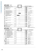
The table
(C Fig
.2)
shows the of
fer and functions of human-machine
interfaces
8.3 Discrete control and indicator units
b Push buttons and pilot lights
v Standard ranges
These interfaces are perfectly adapted to situations where the operator
and the machine exchange little information which is limited to discr
ete
signals (run orders and status indications).
They ar
e rugged and r
eliable electr
omechanical components that are easy
to implement, ergonomic and not vulnerable to ambient conditions. They
can be fitted with a wide range of round or square control heads.
They have a standard colour code which makes them easy to identify (see
note).
They are intuitive or reflex devices (e.g. for emergency stops).
For this reason, they are used for safety operations which require controls
that are as simple and direct as possible.
DESIGN COMMISSIONING OPERATING MAINTENANCE
Product
PB YES YES YES
Integrated dialogue
YES YES YES
Operator CAD YES YES Possible
Dialogue software
Supervision CAD YES YES Possible
softwar
e
Function
PB, Supervision, PB, Supervision,
Operation Operator Operator
dialogue dialogue
Integrated
dialogue
Diagnostic (Supervision and
Operator
dialogue
possible)
Integrated dialogue
(Supervision and
Adjustment Operator
dialogue
possible)
Integrated
CAD dialogue PC
software Operator, adjustment
and others Supervision software
software
A Fig. 2 Offer and functions of human machine interfaces
8.3 Discrete control and indicator units
8. Human-machine
interface
189
Note : the IEC 60204-1 standard stipulates the colour codes that pilot lights and
push buttons must be:
- red light: emergency – hazardous situation requiring immediate action (pressure
not within safety limits, over-travel, broken coupling, etc.);
- yellow light: abnormal – an abnormal situation likely to lead to a hazardous
situation (pressure not within normal limits, tripping of protection device, etc.);
- white light: neutral – general information (supply voltage, etc.);
- red push button: emergency - action to counter danger (emergency stop, etc.);
- yellow push button: abnormal - action to counter abnormal conditions
(intervention to restore an automatic cycle run, etc.).
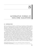
The push button interface is used for general stop and start control and
safety circuit control (emergency stops).
They exist in diameters of 16, 22 and 30mm (NEMA standards) and different
designs
(C Fig 3):
- chromium-plated metal bezel, for all heavy-duty applications in harsh
industrial environments;
- plastic for harsh environments: chemical and food industries.
• Operating head
There is a wide range of control heads:
- flush, protruding, recessed or booted;
- mushroom;
- double-headed;
- mushroom with latching;
- “emergency stop”;
- switch with toggle, handle, key, 2 or 3 set or pull-off positions;
- metal pin (multidirectional control);
- flush, protruding or booted pilot lights.
The modular design of control and indicator units offers great flexibility of
use.
Pilot lights and illuminated buttons are fitted with filament lamps or LEDs.
They are mains powered and have a voltage reducer or built-in transformer.
The control units can hold 1 to 6 NO or NC contacts compatible with 24V
PLC inputs.
• Ruggedness and reliability
Push buttons and pilot lights ar
e subject to harsh environmental
conditions. Life time of a push button is around 1 million of operations.
They must be designed to withstand shock tests according to the IEC
60947-5-5 standard. As an example, according to the standard, an
emergency stop button must withstand 5.5 Joules without failure, the
Harmony push button range can withstand 17 Joules.
v Buttons and pilot lights for printed cir
cuit connection
(C Fig
.
4)
The 22mm diameter range exists in a version for "printed cir
cuit connection".
These products are designed for repeated dialogue media with an identical
diagram. The control and indicator units are from the standard range. The
electrical blocks specific to these versions have output contacts to weld
them to printed circuits.
8
A Fig. 3 Push buttons Harmony design
A Fig. 4 Push button and pilot light for printed
circuit board
8.3 Discrete control and indicator units
8. Human-machine
interface
190
• Square-headed key buttons and pilot lights
These devices ar
e mounted at intervals of 19,05 mm (3/4 ”) in holes
16 mm in diameter
. They are used to make compact control units when
space is at a premium and they can be linked to input keyboards.
Key buttons are touch-sensitive. They can have a silver or gold contact.
• LED pilot lights (C Fig 5)
LED’s for 0.8 and 12 mm mountings are especially recommended when
space is limited or when there are a lot of indicating elements (low power
dissipation).
They have many advantages:
- excellent resistance to shocks, vibrations and voltage surges,
- long lifetime (>100,000 hrs),
- low consumption making them directly compatible with PLC’s outputs.
v Illuminated beacons and banks (C Fig.6)
Beacons and banks are optical or sound indicators to view machine and
alarm statuses over great distances and through 360°.
• Beacons
These have a single illuminated lens or flash unit, which is colourless, green,
red, orange or blue.
• Banks
These have a variable composition made up of lens units, flash units or
sound signals. These elements are slotted together. Electrical connection
is made automatically as they are stacked together.
• IEC 60204-1 standard
The IEC 60204-1 standard stipulates the colour codes corresponding to
displayed messages :
Light signalling
- Red: urgent (immediate action required)
- Yellow / Orange: anomaly (checking and/or intervention required)
- Green: normal condition (optional)
- Blue: obligatory action (action required from the operator)
- White: monitoring (optional)
Flashing lights
- For distinction or specific information:
- Attract more attention
-
Call for immediate action
- Indicate discordance between the instruction and the actual status
- Indicate a change in cycle (flashing during transition).
Flash and rotating mirror beacons
- A more powerful signal for top priority information or longer distance
signalling (conforming to IEC 60073).
Buzzer and sirens
-
Recommended in environments subject to considerable light or sound
interfer
ence or when the pr
esence of the operator is of higher importance.
v Joysticks (C Fig
.7)
Joysticks usually use contactors to control movement through one or two
axes, such as travel/direction or raising/lowering on small hoisting
equipment.
They usually have 2 to 8 directions, with 1 or 2 contacts per direction,
with or without r
etur
n to zero.
Some joysticks have a “dead man” contact at the end of the lever
.
A Fig. 5 Led’s pilot lights
A Fig. 6 Illuminated beacons and banks
A Fig. 7 Telemecanique joysticks
8.4 Schneider Electric Discrete Control and
Indicator Unit offer
8.5 Advanced human-machine interfaces
8. Human-machine
interface
191
8.4 Schneider Electric Discrete Control and Indicator Unit offer
b Harmony range (Telemecanique)
The illustration above shows part of the Harmony range of discr
ete
control and indicator units. These products are noted for their:
-
simplicity: the elements clip together for safe and easy assembly;
-
ingenuity: LED technology used for all light functions;
-
flexibility: modular design to upgrade the products along with the
automation system;
-
ruggedness: mechanical performances well above standard;
-
compactness: overall dimensions are the smallest on the market;
-
multiple connection options: 2.8 x 0.5 Faston lugs, welded lugs,
tags, scr
ew-in terminals or terminal clamps.
8.5 Advanced human-machine interfaces
Progress in electronics and communication systems has led to the development
of human-machine interfaces with enhanced user-friendly functions.
These interfaces make it possible to set product parameters, obtain information
on actuators, such as current consumption, temperature, speed, etc.
The operator can also choose the working language by setting it in advance.
b Special embedded control panel
Special dialogue tools built into products offer performance tailored to the
needs of operating adjustment and efficient diagnostics.
The panel
(C Fig
.9)
is fr
om an
Altivar A
TV 71
T
elemecanique.
v Main featur
es
-
Graphic screen with custom display.
- Plain text entry with 6 languages available (Chinese, English, French,
German, Italian and Spanish) and others on option.
- Browse button to navigate the menus easily.
-
“Simply Start” menu for a quick start to get the most fr
om Altivar 71
performance immediately.
- “Function” keys for shortcuts, online help or to configure for
applications.
-
Permanent display of motor operation settings.
v Main advantages
- Clear display with text on 8 lines and graphic views. Legibility up to
5 m
(C Fig
.10)
.
-
Flexibility through remote operation: on a cabinet door avec with IP
54 or IP 65 pr
otection for multipoint connection to several speed
controllers.
-
Storage 4 configurations can be stored for transfer to other speed
controllers.
8
A Fig. 8 Harmony offer
A Fig. 9 ATV71 embendded control panel
A Fig. 10 Example of ATV71 messages
8.5 Advanced human-machine interfaces
8. Human-machine
interface
192
- Ease to use with function keys for shortcuts, direct access and online
help, maximum and minimum parameter display
.
-
Ergonomic br
owse button. Navigate the dropdown menu quickly and
easily with just one finger.
-
Custom parameters, viewing screens, monitor bar, user menu
creation, etc.
-
Pr
otection
of parameters, visibility contr
ol, password protection for
safe and easy access to custom configurations.
Many macro-configurations already integrated. They ared designed for a
wide range of uses and applications: handling, hoisting, general use,
connection to field bus, PID r
egulation, master, slave, etc.
They are easy to modify.
A wealth of varied services is available thr
ough the graphic terminal to
help tune and diagnose machines.
b Screen/keyboard terminals
Unlike embedded terminals, screens and keyboards are generic products
that adapt to any application.
As we saw in the table above
(C Fig.2), screen terminals are used in both
commissioning and operation.
Depending on their type and software, they can play an important part in
maintenance operations.
Terminals communicate with the process via the appropriate communication
bus and are an integral part of the dialogue and data chain.
To illustrate what screen/keyboard terminals can do, we shall take a look
at the Telemecanique Magelis offer.
These graphic terminals (with an LCD touch screen of 5.7” to 12.1” and
keyboard or touch screen of 10.4”) provide simple access to graphic
solutions for controlling and/or supervising automated units.
Communication performance are guaranteed by a direct connection to an
Ethernet TCP/IP network.
v Important features
• Designed for harsh industrial envir
onments
- rugged and compact;
- reliable ergonomic control by keyboard or touch screen;
- highly contrasted screens for excellent legibility.
• Maintenance & diagnostics via the web
- remote control via Internet Explorer;
- access to operator console diagnostic information via HTML pages;
-
remote diagnostics;
- automatic emailing.
• Compatible and upgradeable
-
API connection available (several manufactur
ers);
- OPC communication (several manufacturers (OPC server);
- TCP/IP network integration;
- Embedded VB Script.
• Innovating HMI concepts
-
decentralised contr
ol stations;
- centralised access to local stations, small control rooms;
- usable throughout the world over as many languages are supported.
8.5 Advanced human-machine interfaces
8. Human-machine
interface
193
Terminal device family figure 11.
Magelis XBT R, S
Compact matrix operator terminals:
- 4 to 8 lines with 5 to 20 prints,
- semi-graphic symbols,
- touch pad and passwor
d.
« ZENSHIN »
Touch screen graphic terminals available in 5.7 - 7.5 - 10.4" dimensions.
Magelis XBT GK
Graphic man machine operating terminals available in 5.7 - 7.5 - 10.4"
dimensions.
Magelis XBT GT
Touch screen colour graphic terminals available in 3.8-5.7-7.4-10.4-
12.1-15” dimensions.
8
• Magelis XBT G touch screen graphic terminals
- Display LCD screen size 5.7” 7.4” 10.4” 12.1”
-
Functions
- representation of variables: alphanumeric, bitmap, bargraph, gauge,
- button, light, clock, flashing light, keypad;
- curves with log;
- incorporated alarm log.
-
Communication
- embedded Ethernet: 10BASE-T (RJ45);
- downloadable protocols: Uni-Telway, Modbus, Modbus TCP/IP.
-
Compatible with Schneider Electric controllers and PLC’s:
Twido, Nano, Modicon TSX Micro, Modicon Premium, Modicon
Quantum.
-
Configuration softwar
e
Vijeo Designer VJD SPU LFUCD V10M (on Windows 2000 and XP).
-
Compact Flash card slot
- Supply voltage 24V =
• Magelis XBT F graphic terminals
- Display LCD scr
een size 10.4”
Format 256-colour TFT
-
Data entry keypad
-
10 dynamic function keys with LED’
s;
- 12 static function keys with LED’s + legends;
- 12 service keys;
- 12 alphanumeric keys + 3 alphanumeric access.
A Fig. 11 Terminal device family
8.5 Advanced human-machine interfaces
8. Human-machine
interface
194
- Touch screen data entry option
- Functions
- representation of variables: alphanumeric, bitmap, bargraph, gauge,
potentiometer, selector;
- recipes: 125 records maximum with 5000 values;
- 16 curves;
- alarm log.
-
Communication
- embedded Ethernet: 10BASE-T/100BASE-TX (RJ45);
-
buses and networks: Fipway, Modbus Plus, and third-party
pr
otocols;
- downloadable protocols: Uni-Telway, Modbus, Modbus TCP/IP.
-
Compatible with Schneider Electric controllers and PLCs
T
wido, Nano, Modicon TSX Micro, Modicon Premium, Modicon
Quantum
-
Configuration software XBT L1003M (on Windows 98, 2000 and XP)
-
Supply voltage 24 V =
b Industrial PC’
s
v Characteristics
Industrial PC’s are characterised by their rugged design enabling them to work
without failure in industrial environments with electromagnetic interference
and harsh climatic conditions. Industrial PC’s can be compact or modular
to fit closely the user’s needs.
The illustrations
(C Fig.12a) shows part of Schneider Electric offer.
A Fig. 12a Partial Industrial Magelis PC offer
8.5 Advanced human-machine interfaces
8.6 Exchange modes
8. Human-machine
interface
195
8
A Fig. 12b Industrial modular PC - Magelis I Display
8.6 Exchange modes
Conventional communication modes such as serial and bus links are
naturally used on most products. They work through drivers embedded in
the configuration software. Networks can also be used.
b Protocols supported
All the core protocols in the =S= offer can be used:
- Uni-TE (Uni-Telway), Modbus, Modbus TCP-IP, FipWay, Modbus Plus;
- third-party protocols are also available;
- features: control graphic and ergonomics, types of automation system
action.
v FactoryCast (on PLC Ethernet plug-in) (C Fig.13)
Remote diagnostic functions via an ordinary internet browser:
- secure access to system diagnostics and application;
- numerical or graphic data display and adjustment;
- Emailing;
- open to customisation and web page creation for diagnostics suited
to user needs.
v FactoryCast HMI
Same diagnostic functions as FactoryCast + new HMI functions
embedded in a PLC module:
- real-time database and PLC data acquisition (1000 variables);
- calculations for pre-processing data;
- advanced alarm management with emailing;
- data ar
chived in r
elational databases (SQL, Oracle, MySQL);
-
a web server the user can customise for an interface suited to
requirements.
v FactoryCast Gateway
New of
fer of intelligent “all-in-one” web gateways in a standalone box
containing:
-
network communication interfaces and Modbus or Uni-T
elway serial
links;
- remote access server (RAS);
- alarm notification by email;
- a web function the user can customise.
Magelis Modular iPC
Easy commissioning with 12” or 15” colour TFT LCD screens,
with or without touch scr
een, with or without a QWERTY
keyboard.
Magelis IDisplay
12, 15, 19” touch screen with a USB port optimising the
man / machine interface.
v Magelis Modular iPC industrial PCs
The modularity and flexibility of the Magelis Modular iPC range (C Fig.12b)
of
fer solutions for the perfect choice of human-machine interface on a PC
base, with easy upgrading and fast maintenance.
A Fig. 13 Example of a remote diagnostic
8.7 Development software
8. Human-machine
interface
196
8.7 Development software
In addition to the terminal hardware, software is also offered to configure
and adapt the terminals to their requisite application.
Below is a description of the Telemecanique Magelis offer. Hardware and
software are combined in a consistent package enabling the user to build
the requisite application in the shortest possible time.
The softwar
e can also be used to communicate with third-party products
to gain optimal flexibility and open-endedness.
b XBT L1003M configuration software
For Magelis terminal displays running under Microsoft Windows 98, 2000
an XP
.
The XBTL1001/L1003 configuration software is provided to build an
interface in order to run or operate a machine. It is applicable to:
- all XBTN/R/H/HM displays, XBTP/PM/E screens with the XBTL1001
software;
- all XBTN/R/H/HM displays, XBTP/PM/E screens et F with the
XBTL1003 software.
Application generated with the XBTL1001/L1003 software are independent
of the protocol being uses. Same dialog application ca be used on PLC’s
coming from any major providers.
v Configuration
The XBTL1001/L1003 configuration software is an user friendly package
to create several family of pages:
- application pages (eventually linked to each other);
- alam pages;
- help pages;
- recipe pages.
b Vijeo Designer, MMI interface software for XBTG / XBTGT
Vijeo Designer is a software workshop for the “Build Time” part and a run
time softwar
e which is downloaded into the XBTG / XBTGT
(C Fig
.14)
.
The ‘Build Time’ part is similar to Visual Studio. The supported operating
systems ar
e Micr
osoft Windows 2000 et XP Professionnal.
The run time softwar
e, the key point of the solution is as user friendly as
possible. It is available in two formats:
- a PC format which runs automatically any time a user wants to emulate
the application on a PC;
- a user’s format which can be downloaded in the background when
debugging has bee made and the application is r
eady to run on the
XBTG / XBTGT.
Additional information ar
e available in the Schneider Electric documentation.
8.7 Development software
8.8 Conclusion
8. Human-machine
interface
197
b Vijeo Citect
Vijeo Look 2.6 a SCADA (Supervision ControlAnd Data Acquisition) aimed
to stand alone terminals
(C Fig.15). If offer a perfect symbiosis between
Web and MMI (Man Machine Interface).
Information are available in the Schneider Electric documentation.
8.8 Conclusion
Human-machine interface is probably the sector in automation which has
made the gr
eatest pr
ogr
ess in the last few years.
This progress is due to increasingly sophisticated and user-friendly
electronics and signal processing.
With the right choice of interface and its configuration, users can contr
ol
pr
ocesses with ever gr
eater exactness and undertake diagnostics and
preventive maintenance to increase productivity by reducing downtime.
8
A Fig. 14 Screen shot of Vijeo designer
A Fig. 15 Screen shot of Vijeo designer