Biện pháp thi công bơm vữa hóa chất Chemical Grouting Bản tiếng anh
Bạn đang xem bản rút gọn của tài liệu. Xem và tải ngay bản đầy đủ của tài liệu tại đây (879 KB, 26 trang )
Package 4: Construction of Sewer Pipes in Ha Dong
and New Urban Area
Method statement for soil improvement by chemical
grouting
Final
submission
TABLE OF CONTENTS
Content
An Xuan Thinh – Song Da 9 Joint Venture
Page
Page 1/26
Package 4: Construction of Sewer Pipes in Ha Dong
and New Urban Area
Method statement for soil improvement by chemical
grouting
Final
submission
1. Overview
1.1. Purpose
In pipe jacking technology, the difficulty of construction work depends on the geological
conditions. Especially, in the cases that strata in unstable, excavation is vulnerable to collapse,
ground is vulnerable to subsidence, or there will be the requirements of protecting underground
structures or reinforcing the stability of receiving shaft, the ground improvement to the sides of
shaft is very necessary.
The method of ground improvement by chemical is one of the treatment solution for improving
the mechanical properties of soil with the main purpose of reinforcing the soil structure and
mitigating the penetration of groundwater. This is a ground improvement method with the
preeminence of its simplicity and convenience compared to other improvement methods.
Chemical ground reinforcement utilizes the chemical solution that their setting times can be
adjusted optionally then injected by pressure into the ground through the pipes arranged in ground
for blocking ground water and reinforcing to ground structure. The features of this improvement
method are as follows:
a. Chemical solution will dispose the existing ground water occupied in the cavities of soil then
solidifies at the gaps between soil particles, but without changing the strata.
b. With the penetration and solidification of this chemical solution, the soil will has its better
cohesion, lower porosity, consequently the ground shall become more solid and lower
permeable.
c. Chemical improvement solution consists of main materials as liquid glass (SiO2 / Na2O),
setting admixture, and other auxiliary materials, which can be mixed in various proportion so
that the setting time of mixed product can be adjusted in a range from few seconds to hours.
1.2. Scope of application
This construction method is applicable for ground improvement at the tunnel eye of the driving
shafts, receiving shafts and intermediate shafts. Include:
The number of driving shaft, receiving shafts and intermediate shafts are shown according to the
technical design drawings provided by the Employer to the Contractor as follows:
An Xuan Thinh – Song Da 9 Joint Venture
Page 2/26
To
Shaft
Number
of
departure
shaft
Number
of arrival
shaft
Number of
intermediate
shaft
No
Route
From
Shaft
1
Vu Trong Khanh street &
Tran Phu street
42.0
43.0
4
4
14
2
Phan Trong Tue street
46.0.2/0
46.0
3
2
11
3
Phung Hung street
43.0
46.0
3
3
16
46.0
14.0
2
2
8
4
Chu Van An street
(Factory)
1.3. Principle of the method of ground improvement
-
Depending on the purpose and characteristics of the soil, the suitable method and materials
shall be applied. The double pipe strainer method (multi-phase) shall be applied for this
work.
-
The double pipe trainer method will be applied via two steps, after completing the drilling
work into ground with a cutting blade jointed a special drill bit:
o
Primary injection: In first step, the fast setting solution (15 seconds) will be
pumped to fill into the saturated cavities in the ground in purpose of making the
ground homogeneous, forming an osmotic area, where the chemical pumped in
stage 2 can penetrate easier.
o
Secondary injection: slow freezing solution will be pumped in second step to
penetrate into the firstly pumped area. At that time, groundwater will be pushed out
of the reinforced area and concurrently the foundation will solidified.
-
Depending on the setting time of solutions, the products of the double pipe strainer method
will have their different properties. Thanks to the adjustment in pumping ratio of 1st and 2nd
steps, the ground improvement will bring a reliable effective for various kind of soil such as
clay, macadam or multi-layer soil.
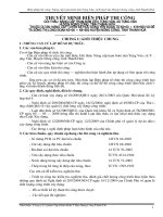
Primary injection
Secondary injection
Flash setting chemical fill the void around
rod, water channel and layer void to stabilize
the ground and the chemical material forms
primary penetration area.
Secondary injection of slow setting material
forms secondary penetration area. Longer gel
time enables minute penetration with low
pressure.
An Xuan Thinh – Song Da 9 Joint Venture
Page 3/26
Flash setting chemical
Double pipe rod
Filling the gap around the rod
Filling water channel and layer gap
Primary penetration area
Special tip unit
Primary injection
Slow setting chemical
Primary penetration area
Secondary injection
2. Specification, standard and relevant documents
2.1. Specification and standard
Technical requirements regarding to this method statement for soil improvement by chemical
grouting include, but are not limited to the following:
-
The Specification – a part of the Contract;
Standards of Micro tunneling Technology for Vietnam;
Japanese pipe jacking standard;
Chemical grouting work – Design guide (version 2019) of Japan Grout Association.
2.2. Relevant documents
Drawings relating to the method statement for soil improvement by chemical grouting
include, but are not limited to, the following:
-
- Drawing number P4-R-CM-JW-005, P4-R-CM-JW-005 in Technical design drawing;
- Working drawing of plan and profile of sewer pipe;
- Working drawing for shafts;
- And other construction drawings.
This method statement shall be read in conjunction with the method statement for pipe
jacking construction and method statement for shaft construction.
3. Site condition
3.1. Construction area
- Construction area is located along Mo Lao, Tran Phu, Phung Hung, Cau Buu, Phan Trong
Tue streets with the high density of population and traffic in Ha Dong district, Hanoi City.
- There are many utilities at the construction area such as lighting system, overhead medium
voltage, lighting pole, water supply pipe, drainage system…
- The Contractor will carry out investigation works in order to determine existing
underground utilities at construction area. In case of any necessary relocation of utilities we
will submit the design document of relocation work for the Engineer’s approval prior to
execution.
- Site fence shall be installed in accordance with construction permit.
3.2. Geotechnical condition
- Based on “Report on geotechnical investigation” of Package 4, strata layers are described as
below:
o Layer 1: Made ground: Clay, sand, concrete, construction waste material, organic
matter;
o Layer 2: Stiff to very stiff brownish grey-reddish grey-greenish grey Clay;
o Layer 3: Stiff brownish grey reddish brown sandy Clay;
o Layer 4: Firm brownish grey-yellowish grey sandy Clay;
o Layer 5: Soft to firm dark grey brownish grey sandy Clay, somewhere mixed with
Organic matter;
o Layer 6: Loose to medium dense grey - dark grey fine to medium Sand, somewhere
interbedded with clayey sand lens;
o Layer 7: Soft to firm brownish grey yellowish grey, dark grey sandy Clay, somewhere
mixed with Organic matter;
According to technical design document, sewer pipeline is located in the layer: Loose to
medium dense grey - dark grey fine to medium Sand, somewhere interbedded with clayey
sand lens;
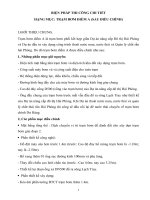
Boring log tipical
Tờ số
1/1
1
Ký hiệu thạch học
Chiều dày lớ p (m)
Đ ộ sâ
u (m)
Cao đ
ộđ
áy lớ p (m)
Lớ p
Đ ộ sâu (m): 15.00
Ngày bắt đầu
13/01/2016
Tỷ lệ
Ngày kết thúc
13/01/2016
1/100
X: 2319262.34
Ng ời mô tả
KS. Trịnh Viết Dũng
Y: 582309.29
Ph ơng pháp
Khoan xoay bơm rửa bằng dung dịch sét
Biểu đ
ồ SPT
Thínghiệm SPT
Mô t ả địa t ầng
N
30
(m)
N1 N N
2 3
2.0
3 4 6
10
U1
1.8-2.0
4.0
3 4 7
11
U2
3.8-4.0
5.7
3 4 5
9
U3
5.5-5.7
8.0
2
1 2
3
U4
7.8-8.0
10.0
5
6 7
13
D1
10.0-10.45
12.0
6 6 9
15
D2
12.0-12.45
13.5
6 7 9
16
D3
13.5-13.95
15.0
7 8 9
17
D4
15.0-15.45
10 20 30 40 50 >50
1.2
1.2
3
5.1
6.3
5
2.7
9.0
6
6.0
15.0
Ghi c hú:
UD: Mẫu nguyên dạng
D: Mẫu không nguyên dạng
Vịtrílấy mẫu UD/R
Vịtrílấy mẫu D/S
Package 4: Construction of Sewer Pipes in Ha Dong
and New Urban Area
Method statement for soil improvement by chemical
grouting
Final
submission
4. Site Organization
SITE ORGANIZATION
Giám đốc dự án
Project manager
Quản lý xây dựng
Construction manager
Kỹ sư công trường
Site Engineer
Quản lý chất lượng
Quality Manager
Kỹ sư chất lượng
Quality Engineer
Qản lý an toàn
Safety Manager
Giám sát an toàn
Safety supervisor
Đội thi công/ Construction team
An Xuan Thinh – Song Da 9 Joint Venture
Page 8/26
Package 4: Construction of Sewer Pipes in Ha Dong
and New Urban Area
Method statement for soil improvement by chemical
grouting
Final
submission
5. Method statement for soil improvement by chemical grouting
5.1. Equipment diagram
Equipment for chemical grouting method includes: mixing equipment used to mix the
chemical mortar solution in accordance with the specified aggregate, the grouting device
used to inject the chemical mortar solution, and the flow meter - pressure (flow meter) to
manage flow during pumping, and drill machine to drill holes for installing tubes in the
ground.
An Xuan Thinh – Song Da 9 Joint Venture
Page 9/26
Package 4: Construction of Sewer Pipes in Ha Dong
and New Urban Area
Method statement for soil improvement by chemical
grouting
Final
submission
5.2. Construction sequence
5.3. Construction method description
a. Preparatory work
- Installing fence for construction site according to the issued construction permit.
- Using total station combined with steel ruler to determine the improvement line,
improvement segment on the ground.
- Checking and locating utility items.
- Storing and preserving materials properly in the designated areas.
- Training workers to ensure proper workflow and safety.
b. Equipment mobilization and installation
- Construction materials and equipment will be mobilized to the site according to the
requirements of each construction phase.
- Installing drilling equipment on site.
- Connect the drill and necessary pumping equipment, mixing (such as drill rod, control
panel, drill bit, ...) to inject the mortar.
c. Drilling
- Set up the machine, start drilling holes (drill down to the designed position).
An Xuan Thinh – Song Da 9 Joint Venture
Page 10/26
Package 4: Construction of Sewer Pipes in Ha Dong
and New Urban Area
Method statement for soil improvement by chemical
grouting
-
Final
submission
Check the verticality with a foam ruler mounted on the drill or with a wire from 2
perpendicular directions.
An Xuan Thinh – Song Da 9 Joint Venture
Page 11/26
Package 4: Construction of Sewer Pipes in Ha Dong
and New Urban Area
Method statement for soil improvement by chemical
grouting
Final
submission
- Measure and check the drilling depth based on the length of the drill rod and the markers
which is marked on the ground.
d. Solution mixing
- Chemical injection shall be done 2 steps.
- Materials for the 1st injection are fast freezing Silica shot (inorganic solution). Standard
formulation for rapid hardeners: Silicarizer (RMG - S2). Solution A and solution B will
be mixed continuously during the mixing process.
- Value of main material for Silicalizer
Evaluation standard: 64TCN 38:1986 and JIS K1408-1966
No
Test description
Unit
Specification
Colorless or light color liquid like
1
Appearance
2
Specific gravity
3
Silicon dioxide SiO2
%
26 ÷ 30
4
Sodium oxide Na2O
%
9 ÷ 12
5
Water-insoluble matter %
An Xuan Thinh – Song Da 9 Joint Venture
starch syrup
1.4 ÷ 1.5
0.5 max
Page 12/26
Package 4: Construction of Sewer Pipes in Ha Dong
and New Urban Area
Method statement for soil improvement by chemical
grouting
Final
submission
SILICARIZER RMG-S2 Short setting blend (per 1500 litter)
Agent
A
Sodium Silicate
250 (200~250) L
Reactant (Sulfuric Acid) 50 (40~80) L
Water
700 (670 ~760) L
Total
1000 L
Setting time: less than l0 seconds
-
Agent
B
Sodium Silicate
125 (105~125 L)
Water
Total
390 (375-395) L
500 L
Materials for the 2nd stuffing are slow freezing Silica shot (inorganic solution). Standard
formulation for slow hardeners: Silicarizer (RMG - L3).
SILICARIZER RMG-L3 Long setting blend (per 1000 litter)
Agent A
Sodium Silicate
Reactant
(Sulfuric Acid)
Water
Total
250 L
50 (40~80) L
700 (670 ~710) L
1000 L
Setting time: less than 24h.
Note: the reagent used is 70-75% sulfuric acid.
-
-
e. Chemical injecting
After completion of hole drilling, injecting work will start from bottom up.
- The grouting at the site will be controlled through the pressure shown on the pump
manometer (0.6Mpa).
Injecting will be done in 2 steps. Height of each injection step: h = 0.25m or 0.5m.
- Start injecting for primary step: fast freezing solution shall be used to fill the empty gap
around the pumping tube.
An Xuan Thinh – Song Da 9 Joint Venture
Page 13/26
Package 4: Construction of Sewer Pipes in Ha Dong
and New Urban Area
Method statement for soil improvement by chemical
grouting
Final
submission
-
Secondary step: slow freezing shall be used to penetrate into the ground.
-
The injecting speed is adjusted within 8 ~ 16l / min.
- Completion of injecting work: Raise step by step, repeat the 1st step, 2nd step in
sequence to the end of working process.
An Xuan Thinh – Song Da 9 Joint Venture
Page 14/26
Package 4: Construction of Sewer Pipes in Ha Dong
and New Urban Area
Method statement for soil improvement by chemical
grouting
Final
submission
5.4. Scope of improvement
The minimum improvement area for driving and arriving as follows construction drawing
design already has approval.
5.5. Volume of injecting chemical
Quantity for injection of chemical grout shall be determined via formula as follows
Q=Vxλ
In which:
Q: Injecting quantity for improvement area (m3 or litter).
V: Volume of improvement area (m3).
λ: Injecting ratio (%) – based on standard: Chemical grouting work – Design guide
(version 2019) of Japan Grout Association, injecting ratio shall be determine is as
follows:
Type of soil
Type
Status
Sand mixed Loose~medium dense
gravel
Medium dense~very dense
Sand
Loose~medium dense
Medium dense~very dense
An Xuan Thinh – Song Da 9 Joint Venture
SPT Value
(N)
Ratio pump via volume (%)
0 ~ 50
36.0
Primary
inject
24.0
>50
31.5
12.6
18.9
0 ~ 30
40.5
13.5
27.0
> 30
31.5
7.0
24.5
Total
Secondary
inject
12.0
Page 15/26
Package 4: Construction of Sewer Pipes in Ha Dong
and New Urban Area
Method statement for soil improvement by chemical
grouting
Cohesive soil
-
Final
submission
Loose~medium dense
0~4
28.0
14.0
14.0
Medium dense~very dense
4 ~8
24.0
12.0
12.0
The volume of chemical grouting at the shaft shall be shown detail in working drawing
and submitted separately period to starting work on site.
5.6. Construction durations
Construction schedule depends on the type of soil, deep and thickness of improvement area.
Basically, the implementation progress is as follows:
No.
Work
1
Mobilization and setting up
equipment
2
Drilling and injecting
3
Demobilization equipment
Implement duration
Remark
1.5 days
4 -5 points/ shift (8 hours)
Improved deep < 8m
2-3 points/ shift (8 hours)
Improved deep > 8m
1 day
6. Manpower, equipment and materials to be used
6.1. Manpower
The expected manpower for the construction of ground improvement by chemical mortar at 1
construction location is as follows:
No
Human work force
Quantity
Task
1
Engineer
01
Construction inspection
2
Surveying specialist
01
Survey, setting up position drill
holes
3
Foreman
01
Directly work
4
Technical worker
04
Directly work
5
Common worker
04
Directly work
6
Driver, mechanic
As required
Operating equipment
The above-mentioned manpower amount is only expected, depending on the work
requirements of each construction phase, the Contractor will mobilize the appropriate
number.
An Xuan Thinh – Song Da 9 Joint Venture
Page 16/26
Package 4: Construction of Sewer Pipes in Ha Dong
and New Urban Area
Method statement for soil improvement by chemical
grouting
Final
submission
6.2. Equipment
The equipment shall be in good condition, have all required calibration certificates and be
checked prior to starting the work. typical equipment to be used for pipe jacking construction
is as per the following table:
Machine name
Drilling
machine
Type and features
Hydraulic machine,
drilling capacity: 100
~ 200m, rod diameter
40.5mm
(5 ~ 18) liters / min x 2
Wattage
(kW)
Number
D2-JS
5,5
1
3,7
01
2 ~ 3 m3/h
20
01
Flow meter
q= 0 ~ 60 litter/ minute
p= 0 ~ 6 Mpa
0,5
01
Measuring
device
φ=25mm
1,5
01
Pump for seal
grout
φ=25mm
0,75
01
Generator
75kva ~ 125kva
01
Material Tank
4 ~10 (ton)
01
Equipment
transfer vehicle
1m3
01
Silicate storage
tanks
0.2 m3
01
Water Tank
1 ~ 5m3
01
Grout pump
Silicarizer
mixer
Remark
NPOT-40
SL3000
Submersible pump
The above equipment is only expected, depending on the actual construction requirement, the
Contractor will mobilize equipment with features suitable/ equivalent to the aforementioned
equipment to ensure construction work.
An Xuan Thinh – Song Da 9 Joint Venture
Page 17/26
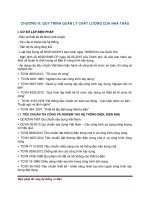
Figure of drilling machine D2-JS
An Xuan Thinh – Song Da 9 Joint Venture
Page 18/26
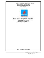
Figure of mixing machine SL-3000
An Xuan Thinh – Song Da 9 Joint Venture
Page 19/26
Package 4: Construction of Sewer Pipes in Ha Dong
and New Urban Area
Method statement for soil improvement by chemical
grouting
Final
submission
Figure of mortar pump NPOT-40
Figure of mortar pump NPOT-40
An Xuan Thinh – Song Da 9 Joint Venture
Page 20/26
Package 4: Construction of Sewer Pipes in Ha Dong
and New Urban Area
Method statement for soil improvement by chemical
grouting
Final
submission
Figure of flow meter
An Xuan Thinh – Song Da 9 Joint Venture
Page 21/26
Package 4: Construction of Sewer Pipes in Ha Dong
and New Urban Area
Method statement for soil improvement by chemical
grouting
Final
submission
7. Quality management
7.1. Material:
Materials for ground improvement must be obtained the Engineer's approval and the
Employer's approval, the supplier will transport the materials directly to the site.
At construction sites, quality control is carried out in the following table:
Time
Content
Quality certification
manufacturers
During mobilizing material
During injecting
○
-
-
○
of
Check the time of freezing
Notes: ○ = Contents to be done
The raw material storage method must be structured to avoid leakage, dispersion and
penetration. In addition, it is necessary to store at the area to facilitate construction work as
well as to manage to avoid theft.
Confirm the amount of solution during construction: To check the frozen state of pumped
materials, before construction and during construction (once in the morning, once in the
afternoon), it is necessary to check and Confirm amount of mixing.
7.2. Checking construction position, drilling length
Marking, accurately measuring the drilling point according to the designed position in
working drawing.
Site engineer and the drilling operator are responsible for performing the drilling with the
position tolerance does not exceeding 5cm. Each hole will be numbered and recorded, this
number is used to control quality.
The drilling length depends on the surface where the machine is located, designed level for
ground improvement, thereby determining the depth.
Need to, check the elevation of the machine and and ground surface at construction area to
determine the detail depth.
7.3. Check the incline and the depth during drilling
All drilled holes must be checked in depth. A check of the depth of the hole is based on the
length of the drill rod and the benchmark located on the ground, which is done by the site
engineer and the operator. The length of the drill rod is calculated as follows: (number of
rods) x (length of 1 drill rod) + (length of drill blade + drill head).
An Xuan Thinh – Song Da 9 Joint Venture
Page 22/26
Package 4: Construction of Sewer Pipes in Ha Dong
and New Urban Area
Method statement for soil improvement by chemical
grouting
Final
submission
When installing the machine, it is necessary to use a level ruler to fix and ensure the
verticality of the machine.
The incline angle of the drill rod will be measured and the site engineer and the drill
operator will regularly check the vertical and inclination angle of drilling rod.
The drilling rod must be enough and be placed near the drilling machine.
7.4. Injecting volume control and completion accepting for soil improvement work
Injecting flow and pump pressure will be controlled by the flow meter and manometer on
the pump, data processed and displayed on the control board. All information will be
recorded automatically.
The content of daily injecting control is shown in the following table:
Item
Control method
Technical Requirement
Verify flow from automatic chart
Discharge flow: 08 - 16 L/ Min
Pump pressure
Determine from automatic
pressure gauges
Stop pump when abnormal
situation occurs and determine the
cause
Pump volume
Verify flow from automatic chart
Ensure the designed quantity
High of step
Verify by ruler
0.25m or 0.5m/step
Discharge
flow
When the pump pressure reaches the designed value (0.6Mpa), it will move on to the next
step even if the design volume has not been reached.
The soil improvement work shall be considered complete and ready for acceptance when:
i)
The injecting chemical for all points of tunnel eye of the shaft are completed;
ii) All inspection as mentioned in sections 7.1 to 7.4 of this method statement are done,
including sufficiently their related documents.
7.5. Control the erupting ground
The arising of the eruption ground when pumping chemical solutions affects the existing
buildings. So it must be avoided.
When pumping chemical solution, it is necessary to measure the current status and the
elevation of the road surface, manage and monitor the pump pressure and flow, when there
is an abnormal situation, it is necessary to stop construction work immediately, adjust the
pump flow again and setting time avoids the high pump pressure and pavement lift.
8. Safety control
An Xuan Thinh – Song Da 9 Joint Venture
Page 23/26
Package 4: Construction of Sewer Pipes in Ha Dong
and New Urban Area
Method statement for soil improvement by chemical
grouting
Final
submission
a. General regulations on safety
-
Training on occupational safety for all workers on site before starting work.
Fully equip labor protection in accordance with regulations during construction.
Regularly check winches, cables and other operating equipment ...
Arrange safety signs on the construction site, preventive instructions, warning signs, guards or
guards to prevent accidents from happening on the site.
- Electrical wiring and cables, chemical pump pipes, hydraulic pump pipes will be covered and
placed in order.
- Providing adequate lighting on site when working night shift.
b. Ensuring safety when using chemical
- During the mobilizing and unloading of raw materials, ensure the specified range when
loading and unloading raw materials. In addition, loading and unloading time must also be
ensured, ensure with not overloading.
- With material handling, it is necessary to determine the placement of the vehicle, the capacity
of the crane, the hook, the cable. With materials unloaded, it should be neatly arranged,
avoiding falling.
- Chemical must be stored in the container and transported to site separately with other material.
- Chemical container must be keep in the separate area.
- The extraction of chemical must be done carefully and at the right place to avoid spillage and
run out side.
- A brick wall is need to built at the chemical storage areas to minimize the spillage on the road
surface when chemical containers are leaked.
- Checking the status of the fluid container need to by carried out frequently.
- Preparing/ arranging adequate manpower and equipment for immediate dealing of chemical
spillage situation.
- In the case of chemical spills, sand shall be used to cover the spilled area and collect the sand,
transport to the approved disposal area.
- During construction, all worker shall be equipped with labor protection tools in accordance to
the safety rules and regulations such as rubber gloves, glass, facemask, boots….
c. Preventing accidents with heavy machinery
- Be sure to use protective equipment.
- When operating the machine, ensure to keep the drilling unit stable from vibration. In
addition, need to confirm the machine has stopped before removing the drill rod.
- When using cranes, it is necessary to keep up with the prescribed level to perform crane
operations.
d. Preventing noise and vibration
- Need to minimize noise and vibration levels during construction.
- Turn off the machine when it is not in use.
e. Impact on the environment
- Do not use the machine with large loads when it is not needed. Turn off the device when it is
not in use.
An Xuan Thinh – Song Da 9 Joint Venture
Page 24/26
Package 4: Construction of Sewer Pipes in Ha Dong
and New Urban Area
Method statement for soil improvement by chemical
grouting
Final
submission
- To avoid leakage, dispersal and permeation of pumped materials, it is necessary to cover
around the mixing area.
- In order to avoid the empty bag of material being blown away when finished construction, it is
necessary to quickly located it in the designated area.
f. Accident prevention with underground utility items
- Before construction, it is necessary to survey whether or not underground utility items, if any,
it is necessary to conduct a meeting before construction.
- In the case of drilling in the vicinity of underground utility item, it is necessary to use plastic
pipes, not swirl, but only use water to press down, to avoid breaking underground item.
g. Prevention of slip and fall accidents
- When climbing on the machine, need to clean around, use the steps to get on the floor of
machine, avoid slipping, falling.
- When hoisting, does not stand under the crane area.
- Check the cable before using. Cable is not good should be rejected immediately.
h. Preventing accidents against people around
- When delivering and unloading raw materials, it must be done within the limit area, security
staff shall be arranged to monitoring work procedure.
- At the gate of construction site, people and vehicles must stop before leaving to confirm around.
- When drilling and injecting, to avoid mud splashes, water it need to be covered with a
barrier. The list of hospitals near the construction site is as follows:
No.
Name of hospital
Phone
number
Address
1
K Tan Trieu hospital
090-496-0818
30 Cau Buu, Tan Trieu, Thanh Tri, Ha Noi
2
Military 103 hospital
024-3356-6713
3
Bach Mai hospital
024-3869-3731
261 Phung Hung, Phuc La, Ha Dong, Ha
Noi
78 Giai Phong, Phuong Dinh, Dong Da, Ha
Noi
An Xuan Thinh – Song Da 9 Joint Venture
Page 25/26