Quy trình thi công đường ống nước tuần hoàn tại Nhiệt điện Thăng Long Hoành Bồ Quảng Ninh
Bạn đang xem bản rút gọn của tài liệu. Xem và tải ngay bản đầy đủ của tài liệu tại đây (84.28 KB, 9 trang )
THANG LONG 2x300MW
THERMAL POWER PLANT PROJECT
Owner
THANG LONG POWER PLANT
JOINT STOCK COMPANY
Owner Consultant
FICHTNER GmbH & Co. KG
EPC Contractor
WUHAN KAIDI ELECTRIC POWER
ENGINEERING CO., LTD.
EPC Engineering
Designer
SOUTHWEST ELECTRIC POWER
DESIGN INSTITUTE CO., LTD.
Document Title:
DESCRIPTION OF INSTALLATION AND LAID DOWN FOR
WELDED PIPE
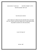
EPC Contract No. : 291210/EPC/TLP-KD
Design Stage:
DESIGN
Document No. :
Rev. No. :
B
50-F416S- S0205-01
Modified according to Owner’s
comments
2
10.Jan.2016
1
25 SEP. 2015
First issue
张雄
李贵雷
李贵雷
徐明
Rev.
Date
Description
Prepared
Checked
Reviewed
Approved
CONTENTS
1.Forward ...................................................................................................... 1
2.Material of welded steel pipe ..................................................................... 1
3.Steel Pipe Welding and Installation............................................................ 2
4. Hydrostatic Test......................................................................................... 6
5. Pipe Laid Down......................................................................................... 7
6. Radiographic examination and supersonic examination........................... 7
7. Construction Acceptance........................................................................... 7
1. Forward
This description declares the basic requirements and matters needed
attention for welded steel pipes(including galvanized steel pipe) for which
the design pressure is less than 1.6MPa during installation, laid down and
construction period. It consists of basic construction requirements for
circulating pipes about welding, installation and water pressure test. The
detail construction procedure and ITP document can be referred to the rated
document which is prepared by the construction department.
2. Material of welded steel pipe
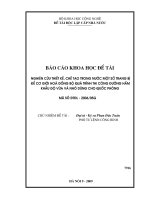
2.1 Mechanical performance of steel products
The mechanical performance and chemical component of welded steel pipe
shall meet the requirement as follows.
Table 2-1
Tension limit of
Mechanical performance(20℃)
Min. yield point
Min. relative extension
Min. impact
strength fy
percentage not less than (%)
toughness
N/mm2
N/mm2
%
J
Q235B
375~500
225
25
27
Q235A
370~460
205~235
25
8
ultimate strength
fu
Steel grade
Steel products delivered to site shall be with factory verify conformity
certificate. In the event of uncertain mechanical performance, sample test
shall be done.
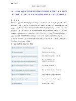
2.2 Steel pipe wall thickness
Steel pipe wall thickness shall meet the requirement of design document
(drawings for water supply and fire fighting department in which steel pipe
1
is applied. For example, fire water pipe, service water pipe, etc). The defect
of steel plate shall not exceed the following limitation:
Table 2-3
Acceptable defect limitation
Thickness of steel plate(mm)
< or = 10
> 10
Scratch marks depth
Not more than 20% of plate
Not more than 2mm
thickness
Crack
Unallowable
Unallowable
3. Steel Pipe Welding and Installation
3.1 Electrode
3.1.1 E4301, E4303 type electrode will be adopted for manual welding,or
H08A, H08MnA type electrode will be adopted for automatic welding.
3.1.2 The electrode coating shall be oven, strong, and never been dampness
damaged.
3.1.3 The electrode shall melt evenly without splash during welding.
3.1.4 The electrode without factory certificate qualification can not be used.
3.2 Welding Technical Requirement
3.2.1 Impurities in the range of 100mm such as paint, rust, greasy dirt, mud,
etc around the crater area shall be cleaned before welding.
3.2.2 The pipe butted end shall be air cut to V-type groove according to
design requirement. Metal burr, residual, flash spot, melting wart, etc. shall
be cleaned completely in groove area before welding.
3.2.3 Butt-welded without backing ring shall be adopted for all pipes.
3.2.4 Longitudinal welded seam of butted pipe section shall be stagger
arrangement. The mutual stagger distance shall not be less than 100mm,
2
and the longitudinal welded seam shall not be put at terminal point of pipe
horizontal and vertical diameter, the longitudinal welded seam shall be put
at point of 45°from vertical central line of the upper half circle in the pipe
cross section, the space between two longitudinal welded seams shall not
be less than 300mm.
3.2.5 Welded seam shall be without sand hole, cavity, air hole or welding
slag. The outside surface of welded seam shall be regular squama scale.
3.2.6 Welding slag, floating leather and scrap shall be cleaned by steel wire
brush after welding work.
3.3 Installation Technical Requirement
3.3.1 Coordinate, elevation and slope of pipes shall meet the design
requirement.
3.3.2 Installation error of pipe shall not exceed the following data.
3.3.2.1 The allowable error of steel pipe diameter after processing will be
±0.001DN (nominal diameter, same as follows).The diameter difference
of the two adjacent pipe mouths shall not be more than 4mm.
3.3.2.2 The ellipticity of pipe shall not be more than 9mm for DN2800
CW pipe, and not more than 6mm for DN1400CW pipe.
3.3.2.3 When adjacent pipe section mouths are misfit mutually, the
difference shall not exceed 1/4 of pipe wall thickness and not exceed 3mm.
If difference exceeds the allowable value, short pipe shall be added for
connection, method of using strong external force or heating extension
3
around pipe outside surface to reduce clearance is forbidden. The length of
short pipe will be more than or equal to 300mm when nominal diameter is
more than or equal to 1000mm, and will be 200 to 300mm when nominal
diameter is less than or equal to 1000mm.
3.3.2.4 The deviant between central lines of pipe butted end shall not
exceed regulation value as follows.
Table 3-1
Deviation Limitation
Pipe diameter (mm)
<1000
≥1000
Deviant (mm)
≤ 1
≤2
3.3.2.5 The deviant of pipe mouth flat surface shall be less than 1mm.
3.3.3 Tension stress of materials shall be prevented during valves or flanges
are installed on pipe, the crater adjacent flange shall be continuous welded
after all bolts have been screwed up uniformity on flange.
3.3.4 Holes of pipeline shall not be located on the welded seam. Temporary
manhole and light hole on pipeline shall not be cut arbitrarily. Only before
the last welded seam of a whole pipe is completed, a temporary manhole is
allowed. Temporary manhole shall be circular and the distance between
manhole and welded seam shall be no less than 100mm.
3.3.5 For the pipe and pipe section with stiffening rings, temporary support
in the pipe shall be considered to avoid distorting if necessary for
transportation.
3.3.6 The special benchmark of axial line and elevation for pipe installation
shall be built in pipe installation place. The benchmark shall be recorded by
4
survey department.
3.4 Stiffening Ring
The installation of stiffening ring which can improve the rigidity of welded
pipe shall meet the following requirements:
3.4.1 Stiffening ring is made of hot-rolled channel steel. The specification
and distance of stiffening ring shall meet the design requirement in
drawings, obvious distortion shall not be found for the channel steel and
stiffening ring.
3.4.2 Stiffening ring is installed on the welded steel pipe and the gap
between the pipe and stiffening ring shall be less than 2mm.
3.4.3 Stiffening ring shall be close circular; the close joint position shall be
at terminal point of pipe 45°from vertical and horizontal central line.
3.4.4 Both sides of joint of stiffening ring with pipe shall be fully and
constantly welded, interval welding is forbidden.
3.4.5 The distance from outer edge of stiffening ring to the cross welded
seam (circular welded seam) between two pipe sections shall no less than
100mm.
3.5 Connection for galvanized steel pipe
Threaded connection or clamping connection or flange connection will be
adopted for galvanized steel pipe.
3.6 Welder’s qualification requirements
The welders must be trained and obtain the permission for welding.
5
4. Hydrostatic Test
4.1 Hydrostatic test of system tightness shall be done for check tightness of
each connection part (welding, deformed apart, flange interface and etc)
after whole pipe engineering finished. The requirements of tender
document will be carried out.
4.2 The test water pressure of hydraulic pipeline will be 1.50multiple of
working pressure, and not less than 0.4 MPa. The test water pressure of
CW pipe shall be 0.4 MPa
4.3 During hydrostatic test of pipeline system is done, the reached test
pressure shall be kept 30min without reduction, then pressure will be
reduced to working pressure for totally and carefully outline check, the
welded seam shall be tapped by 1.5kg small hammer. Test is acceptable if
welded seam, deformed apart, interface and etc have no breakage, seepage,
leakage and no change indicated on pressure gauge.
4.4 Following items shall be done before pipe system tightness test
4.4.1 Welding, connection and etc installation works shall be finished and
acceptable after check.
4.4.2 Pressure gauge using for test shall be pre-check accuracy.
4.4.3 Plan for technical, safety and organizing shall be prepared.
4.4.4 Pipe system be test shall be separated from operation pipe by
bulkhead.
4.4.5 Air in pipe shall be discharged before test.
6
4.5 Anybody can not stay in trench during test.
4.6 Others requirement about pressure test shall be according to coherent
technical standard.
5. Pipe Laid Down
The requirements of buried steel pipes refer to 50-F416S-S5102.
6. Radiographic examination and supersonic examination
The radiographic and ultrasonic examination of the piping weld shall be
duly conducted according to rated standards and Codes.
7. Construction Acceptance
7.1 Two steps construction acceptance of welded pressurized steel pipe
shall be adopted. First step is done according to process step during
construction period, and the second step is done after whole pipe system
welding, installation and construction finished.
7.2 Acceptance check of weld pressurized steel pipe shall be combined by
builder, operator and others related division. The acceptance shall have
signature.
7