3D Fibre Reinforced Polymer CompositesL pptx
Bạn đang xem bản rút gọn của tài liệu. Xem và tải ngay bản đầy đủ của tài liệu tại đây (6.9 MB, 262 trang )
3D
Fibre Reinforced
Polymer
Composites
L.
Tong,
A.P.
Mouritz and M.K. Bannister
Elsevier
3D
Fibre Reinforced Polymer
Composites
Elsevier Science Internet Homepage
-
Consult the Elsevier homepage for
full
catalogue information on all books, journals and electronic
products and services.
Elsevier
Titles
of
Related Interest
VALERY V. VASILEV
&
EVGENY V. MOROZOV
Mechanics and Analysis of Composite Materials
ISBN
0
08 042702 2
JANG-KYO
KIM
&
YIU WING MAI
Engineered Interfaces in Fiber Reinforced Composites
ISBN:
0
08
042695 6
J.G.
WILLIAMS
&
A. PAVAN
Fracture of Polymers, Composites and Adhesives
ISBN
0
08 0437
10
9
D.R. MOORE, A. PAVAN
&
J.G.
WILLIAMS
Fracture Mechanics Testing Methods for Polymers Adhesives and Composites
ISBN
0
08 043689
7
A. BAKER, F. ROSE
&
R.
JONES
Advances in the Bonded Composite Repair of Metallic Aircraft
ISBN:
0
08
042699 9
Related Journals:
Composite Structures
-
www.elsevier.com/locate/comustruct
Composites Part A: Applied Science and Manufacturing
-
www.elsevier.com/locate/comuositesa
Composites Part B: Engineering
-
www.elsevier.com/locate/comuositesb
Composites Science and Technology
-
www.elsevier.com/locate/comuscitech
Major Reference
Work:
Comprehensive Composite Materials
-
www.elsevier.com/locate/isbn/0080429939
To
contact the Publisher
Elsevier Science welcomes enquiries concerning publishing proposals: books, joumal special issues, conference
proceedings, etc.
All
formats and media can be considered. Should
you
have
a
publishing proposal
you
wish
to
discuss, please contact, without obligation, the publisher responsible
for
Elsevier's Composites and Ceramics
programme:
Emma Hurst
Assistant Publishing Editor
Elsevier Science Ltd
The Boulevard, Langford Lane
Kidlington, Oxford
OX5
IGB,
UK
Phone:
+44
1865843629
Fax:
+44
1865 843931
E.mail: e.hurst @elsevier.com
General enquiries, including placing orders, should be directed to Elsevier's Regional Sales Offices
-
please access the Elsevier homepage for full contact details (homepage details at the top
of
this page).
books
to search for more Elsevier books, visit the Books Butler at
?
'\
6
p
8-
b
*<"
+-
'"i
e
P
3D
Fibre Reinforced Polymer Composites
Liyong Tong
School of Aerospace, Mechanical
and
Mechatronic Engineering,
University of Sydney, Sydney, Australia
Adrian
P. Mouritz
Department of Aerospace Engineering,
Royal Melbourne Institute
of
Technology, Melbourne, Australia
Michael
K.
Bannister
Cooperative Research Centre for Advanced Composite Structures Ltd
&
Department
of
Aerospace Engineering,
Royal Melbourne Institute of Technology, Melbourne, Australia
2002
ELSEVIER
AMSTERDAM
-
BOSTON
-
LONDON -NEW YORK
-
OXFORD
-
PARIS
SAN DIEGO
-
SAN FRANCISCO
-
SINGAPORE
-
SYDNEY
-
TOKYO
ELSEVIER
SCIENCE
Ltd
The Boulevard,
Langford
Lane
Kidlington, Oxford
OX5
IGB,
UK
Q
2002
Elsevier
Science
Ltd.
All
rights
reserved.
This work is protected under copyright by Elsevier Science, and the following tms and conditions apply to its
use:
Photocopying
Single photocopies of single chapters may be made for personal use
as
allowed by national copyright laws. Permission of the Publisher
and payment of a fee is required for all other photocopying, including multiple or systematic copying, copying for advertising
or
promotional purposes, resale, and all forms of document delivery. Special rates
are
available for educational institutions that wish to make
photocopies for non-profit educational classroom use.
Permissions may be sought directly from
Elsevier
Science via
their
homepage
()
by selecting ‘Customer
Support’ and then ‘Permissions’. Alternatively
you
can send an email to:
,
or fax to:
(+44)
1865 853333.
In the USA,
users
may clear permissions and make payments through the Copyright Clearance Center, Inc.,
222
Rosewood Drive,
Danvers, MA
01
923.
USA phone:
(+I)
(978)
7508400,
fax:
(+1) (978)
7504744.
and in
the
UK through the Copyright Licensing Agency
Rapid Clearance Service (CLARCS),
90
Tottenham Court Road, London WlP OLP,
UK
phone:
(4)
207 631
5555;
fax:
(4)
207
631
5500.
Other countries may have a local reprographic rights agency
for
payments.
Derivative Works
Tables
of
contents may be reproduced for internal circulation, but permission
of
Elsevier
Science is required
for
external resale
or
distribution of such material.
Permission of the Publisher is required for
all
other derivative works, including compilations
and
translations.
Electronic Storage or Usage
Permission
of
the Publisher
is
required
to
store
or
use electronically any material contained in this work, including any chapter or pan
of a chapter.
Except
as
outlined above, no part
of
this work may
be
reproduced,
stored
in
a
retrieval
system
or
transmitted in any
form
or
by any means,
electronic, mechanical, photocopying, recording
or
otherwise, without prior written permission of the Publisher.
Address permissions requests to: Elsevier Science Global Rights Department, at the mail, fax and e-mail addresses noted above.
Notice
No
responsibility is assumed by the Publisher for any injury
andlor
damage to persons
or
property as a matter of products liability,
negligence
or
otherwise,
or
from any use or operation of any methods, products, instructions or ideas contained in the material herein.
Because
of
rapid advances in the medical sciences, in particular, independent verification of diagnoses and drug dosages should be made.
First edition
2002
Library
of
Congress Cataloging in Publication Data
A catalog record
from
the
Library of Congress has been applied
for.
British Library Cataloguing in Publication
Data
A
catalogue
record
from
the British Library has been
applied
for.
ISBN
0-08-043938-1
8
The paper used in this publication
meets
the requirements
of
ANSINSO
239.48-1992
(Permanence of Paper).
Printed in the Netherlands.
To my wife Hua and my children Richard and Victoria L. Tong
To my wife Jenny and my children Lauren and
Christian
A.P.
Mouritz
To
my wife
Ruth
and my children Lachlan and Emma
M.K.
Bannister
Preface
Fibre reinforced polymer
(FRP)
composites are used in almost every type of advanced
engineering structure, with their usage ranging from aircraft, helicopters and spacecraft
through to boats, ships and offshore platforms and to automobiles, sports goods,
chemical processing equipment and civil infrastructure such
as
bridges and buildings.
The usage of
FRP composites continues to grow at an impressive rate
as
these materials
are used more in their existing markets and become established in relatively new
markets such as biomedical devices and civil structures.
A key factor driving the
increased applications of composites over recent years is the development of new
advanced forms of
FRP
materials. This includes developments in high performance
resin systems and new styles of reinforcement, such
as
carbon nanotubes and
nanoparticles.
A
major driving force has been the development of advanced
FRP
composites reinforced with a three-dimensional
(3D)
fibre structure.
3D
composites
were originally developed in the early
1970s, but it has only been in the last
10-
15
years
that major strides have been made to develop these materials to
a
commercial level
where they can be used in both traditional and emerging markets.
The purpose of this book is to provide an up-to-date account of the fabrication,
mechanical properties, delamination resistance, impact damage tolerance and
applications of
3D
FRP composites. The book will focus on
3D
composites made using
the textile technologies of weaving, braiding, knitting and stitching
as
well
as
by
z-
pinning. This book is intended for undergraduate and postgraduate students studying
composite materials and also for the researchers, manufacturers and end-users of
composites.
Chapter
1
provides a general introduction to the field
of
advanced
3D
composites.
The chapter begins with a description of the key economic and technology factors that
are providing the impetus for the development of
3D
composites. These factors include
lower manufacturing costs, improved material quality, high through-thickness
properties, superior delamination resistance, and better impact damage resistance and
post-impact mechanical properties compared to conventional laminated composites.
The current and potential applications of
3D
composites are then outlined in Chapter
1,
including a description of the critical issues facing their future usage.
Chapter
2
gives a description of the various weaving, braiding, knitting and stitching
processes used to manufacture
3D
fabrics that are the preforms to
3D
composites. The
processes that are described range from traditional textile techniques that have been
used
for
hundreds of years up to the most recent textile processes that are still under
development. Included in the chapter is an examination of the affect the processing
parameters of the textile techniques have on the quality and fibre architecture of
3D
composites.
The methods and tooling used to consolidate
3D
fabric preforms into
FRP
composites are described in Chapter
3.
The liquid moulding methods used for
consolidation include resin transfer moulding, resin film infusion and
SCRIMP.
The
benefits and limitations of the different consolidation processes are compared for
producing
3D
composites. Chapter
3
also gives an overview of the different types of
processing defects (eg. voids, dry spots, distorted binder yams) that can occur in
3D
composites using liquid moulding methods.
A review
of
micro-mechanical models that are
used
or have a potential to be used to
theoretically analyse the mechanical properties of 3D textile composites
is
presented in
Chapter
4.
Models for determining the in-plane elastic modulus of 3D composites
are
described, including the Eshlby, Mori-Tanaka, orientation averaging, binary and unit
cell methods. Models for predicting the failure strength are also described, such
as
the
unit cell, binary and curved beam methods. The accuracy and limitations of models for
determining the in-plane properties
of
3D composites are assessed, and the need for
more reliable models is discussed.
The performance
of
3D composites made by weaving, braiding, knitting, stitching
and z-pinning are described in Chapters
5
to
9,
respectively. The in-plane mechanical
properties and failure mechanisms of 3D composites under tension, compression,
bending and fatigue loads are examined Improvements to the interlaminar fkacture
toughness, impact resistance and damage tolerance
of
3D composites are also described
in detail. In these chapters the gaps in our understanding of the mechanical
performance and through-thickness properties of 3D composites are identified for future
research.
We
thank
our colleagues with whom we have researched and developed 3D
composites over the last ten years, in particular to Professor I. Herszberg, Professor
G.P.
Steven, Dr
P.
Tan, Dr K.H. Leong, Dr P.J. Callus, Dr
P.
Falzon, Mr
K.
Houghton, Dr
L.K. Jain and Dr
B.N.
Cox. We are thankful to many colleagues, in particular to
Professors T W. Chou,
0.0.
Ochoa, and P. Smith, for their kind encouragement in the
initiation of this project. We are indebted to the University
of
Sydney, the Royal
Melbourne Institute of Technology and the Cooperative Research Centre for Advanced
Composite Structures Ltd. for allowing the use
of
the facilities we required in the
preparation of this book. LT and APM are grateful for funding support of the
Australian Research Council (Grant
No.
C00107070, DP0211709), Boeing Company,
and Boeing (Hawker de Havilland)
as
well as the Cooperative Research Centre for
Advanced Composite Structures Ltd. We are also thankful to the many organisations
that kindly granted permission to use their photographs, figures and diagrams in the
book.
L.
Tong
School
of
Aerospace, Mechanical
&
Mechatronic Engineering
University
of
Sydney
A.P. Mouritz
Department
of
Aerospace Engineering
Royal Melbourne Institute
of
Technology
M.K.
Bannister
Cooperative Research Centre for Advanced Composite Structures Ltd
&
Department
of
Aerospace Engineering
Royal Melbourne Institute
of
Technologv
Table
of
Contents
Preface
vii
Chapter
1
Introduction
1.1 Background
1.2 Introduction to 3D
FRP
Composites
1.2.1 Applications
of
3D Woven Composites
1.2.2 Applications of 3D Braided Composites
1.2.3
3D Knitted Composites
1.2.4 3D Stitched Composites
1.2.5 3D 2-Pinned composites
Chapter
2
Manufacture
of
3D
Fibre
Preforms
2.1 Introduction
2.2 Weaving
2.2.1 Conventional Weaving
2.2.2 Multilayer
or
3D Weaving
2.2.3
3D Orthogonal Non-Wovens
2.2.4 Multiaxial Weaving
2.2.5 Distance Fabrics
2.3.1 2D Braiding
2.3.2 Four-Step 3D Braiding
2.3.3 Two-step 3D Braiding
2.3.4 Multilayer Interlock Braiding
2.4.1 Warp and Weft Knitting
2.4.2 Three-Dimensional Shaping
2.4.3
Non-Crimp
Fabrics
2.5.1 Traditional Stitching
2.5.2 Technical Embroidery
2.5.3 2-Pinning
2.3 Braiding
2.4
Knitting
2.5 Stitching
2.6 Summary
Chapter
3
Preform
Consolidation
3.1 Introduction
3.2 Liquid Moulding Techniques
3.2.1
Resin
Transfer Moulding
3.2.2
Resin
Film Infusion
3.2.3 SCRIMP-based Techniques
3.3 Injection Equipment
3.4
Resin
Selection
3.5 Preform Considerations
3.6
Tooling
1
1
6
7
10
11
11
12
13
13
13
13
15
19
22
22
22
24
25
29
31
32
32
36
37
40
40
43
45
45
47
47
48
48
49
51
52
54
56
57
3.6.1 Tool Materials
3.6.2 Heating and Cooling
3.6.3 Resin Injection and Venting
3.6.4 Sealing
3.7 Component Quality
3.8 Summary
Chapter
4
Micromechanics Models
for
Mechanical Properties
4.1 Introduction
4.2 Fundamentals in Micromechanics
4.2.1 Generalized Hooke’s Law
4.2.2 Representative Volume Element and Effective Properties
4.2.3 Rules of Mixtures and Mori-Tanaka Theory
4.2.4 Unit Cell Models
for
Textile Composites
4.3 Unit Cell Models for 2D Woven Composites
4.3.1 One-Dimensional (1D) Models
4.3.2 Two-Dimensional (2D) Models
4.3.3 Three-Dimensional (3D) Models
4.3.4 Applications
of
Finite Element Methods
4.4 Models for 3D Woven Composites
4.4.1 Orientation Averaging Models
4.4.2 Mixed Iso-Stress and Iso-Strain Models
4.4.3 Applications of Finite Element Methods
4.4.3.1
3D
Finite Element Modelling Scheme
4.4.3.2 Binary Models
4.5.1 Braided Composites
4.5.2 Knitted Composites
4.6 Failure Strength Prediction
4.5 Unit Cell Models for Braided and Knitted Composites
Chapter
5
3D
Woven Composites
5.1 Introduction
5.2 Microstructural Properties of
3D
Woven Composites
5.3
In-Plane Mechanical Properties of
3D
Woven Composites
5.3.1 Tensile Properties
5.3.2 Compressive Properties
5.3.3 Flexural Properties
5.3.4 Interlaminar Shear Properties
5.4 Interlaminar Fracture Properties of 3D Woven Composites
5.5 Impact Damage Tolerance
of
3D Woven Composites
5.6
3D Woven Distance Fabric Composites
Chapter
6
Braided Composite Materials
6.1 Introduction
6.2 In-Plane Mechanical Properties
6.2.1 Influence of Braid Pattern and Edge Condition
6.2.2 Influence
of
Braiding Process
6.2.3 Influence
of
Yarn Size
6.2.4 Comparison with 2D Laminates
57
58
58
59
60
61
63
63
64
64
66
68
70
70
71
78
81
88
90
91
92
96
97
99
100
100
103
104
1 07
1 07
108
113
113
123
126
127
128
132
133
137
137
138
138
140
141
143
6.3
Fracture Toughness and Damage Performance
6.4
Fatigue Performance
6.5
Modelling of Braided Composites
6.6
Summary
Chapter
7
Knitted Composite Materials
7.1
Introduction
7.2
In-Plane Mechanical Properties
7.2.1
Tensile Properties
7.2.2
Compressive Properties
7.2.3
In-Plane Properties
of
Non-Crimp Fabrics
7.3
Interlaminar Fracture Toughness
7.4
Impact Performance
7.4.1
Knitted Composites
7.4.2
Non-Crimp Composites
7.5
Modelling of Knitted Composites
7.6
Summary
Chapter
8
Stitched Composites
8.1
Introduction to Stitched Composites
8.2
The Stitching Process
8.3
Mechanical Properties
of
Stitched Composites
8.3.1
Introduction
8.3.2
Tension, Compression and Rexure Properties
of
Stitched Composites
8.3.3
Interlaminar Shear Properties
of
Stitched Composites
8.3.4
Creep Properties
of
Stitched Composites
8.3.5
Fatigue Properties
of
Stitched Composites
8.4
Interlaminar Properties of Stitched Composites
8.4.1
Mode
I
Interlaminar Fracture Toughness Properties
8.4.2
Mode
11
Interlaminar Fracture Toughness Properties
8.5.1
Low Energy Impact Damage Tolerance
8.5.2
Ballistic Impact Damage Tolerance
8.5.3
Blast Damage Tolerance
8.5
Impact Damage Tolerance
of
Stitched Composites
8.6
Stitched Composite Joints
Chapter
9
Z-Pinned Composites
9.1
Introduction
9.2
Fabrication of Z-Pinned Composites
9.3
Mechanical Properties
of
Z-Pinned Composites
9.4
Delamination Resistance and Damage Tolerance
of
Z-Pinned Composites
9.5
Z-Pinned Joints
9.6
Z-Pinned Sandwich Composites
143
145
145
146
147
147
149
149
154
156
158
159
159
161
161
162
163
163
164
169
169
170
176
178
179
182
182
189
195
195
199
200
20
1
205
205
206
209
21 1
216
217
References
219
Subject Index
237
Chapter
1
Introduction
1.1
BACKGROUND
Fibre reinforced polymer
(FRP)
composites have emerged from being exotic materials
used only in niche applications following the Second World War, to common
engineering materials used in a diverse range of applications. Composites are now used
in aircraft, helicopters, space-craft, satellites, ships, submarines, automobiles, chemical
processing equipment, sporting goods and civil infrastructure, and there is the potential
for common use in medical prothesis and microelectronic devices. Composites have
emerged as important materials because of their light-weight, high specific stiffness,
high specific strength, excellent fatigue resistance and outstanding corrosion resistance
compared to most common metallic alloys, such as steel and aluminium alloys. Other
advantages of composites include the ability to fabricate directional mechanical
properties, low thermal expansion properties and high dimensional stability. It is the
combination of outstanding physical, thermal and mechanical properties that makes
composites attractive to use in place of metals in many applications, particularly when
weight-saving is critical.
FRP
composites can be simply described as multi-constituent materials that consist
of reinforcing fibres embedded in a rigid polymer matrix. The fibres used
in
FRP
materials can be in the form of small particles, whiskers or continuous filaments. Most
composites used in engineering applications contain fibres made of glass, carbon
or
aramid. Occasionally composites are reinforced with other fibre types, such as boron,
Spectra@ or thermoplastics. A diverse range of polymers can be used as the matrix to
FRP
composites, and these
are
generally classified as thermoset (eg. epoxy, polyester)
or thermoplastic (eg. polyether-ether-ketone, polyamide) resins.
In
almost all engineering applications requiring high stiffness, strength and fatigue
resistance, composites
are
reinforced with continuous fibres rather than small particles
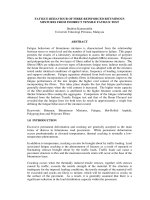
or whiskers. Continuous fibre composites are characterised by a two-dimensional (2D)
laminated structure in which the fibres are aligned along the plane (x-
&
y-directions) of
the material,
as
shown in Figure
1.1.
A
distinguishing feature of
2D
laminates is that
no
fibres are aligned
in
the through-thickness (or
z-)
direction. The lack of through-
thickness reinforcing fibres can
be
a disadvantage
in
terms of cost, ease of processing,
mechanical performance and impact damage resistance.
A serious disadvantage
is
that the current manufacturing processes for composite
components can be expensive. Conventional processing techniques used to fabricate
composites, such as wet hand lay-up, autoclave and resin transfer moulding, require a
high amount of skilled labour to cut, stack and consolidate the laminate plies into a
preformed component.
In
the production of some aircraft structures up to
60
plies of
carbon fabric or carbodepoxy prepreg tape must
be
individually stacked and aligned by
hand. Similarly, the hulls of some naval ships
are
made using up to
100
plies of woven
2
30
Fibre Reinforced Polymer Composites
glass fabric that must be stacked and consolidated by hand. The lack of a z-direction
binder means the plies must be individually stacked and that adds considerably to the
fabrication time. Furthermore, the lack of through-thickness fibres means that the plies
can slip during lay-up, and this can misalign the fibre orientations in the composite
component. These problems can be alleviated to some extent by semi-automated
processes that reduce the amount of labour, although the equipment is very expensive
and is often only suitable for fabricating certain types of structures, such as flat and
slightly curved panels.
A
further problem with fabricating composites is that production
rates are often low because of the slow curing of the resin matrix, even at elevated
temperature.
Y
Figure
1.1
Schematic of the fibre structure to a
2D
laminate
Fabricating composites into components with a complex shape increases the cost even
further because some fabrics and many prepreg tapes have poor drape. These materials
are not easily moulded into complex shapes, and as a result some composite
components need to be assembled from a large number of separate parts that must be
joined by co-curing, adhesive bonding
or
mechanical fastening. This is a major problem
for the aircraft industry, where composite structures such as wing sections must be made
from a large number of smaller laminated parts such as skin panels, stiffeners and
stringers. These fabrication problems have impeded the wider use of composites in
some aircraft structures because it is significantly more expensive than using aircraft-
grade aluminium alloys.
As
well as high cost, another major disadvantage of
2D
laminates is their low
through-thickness mechanical properties because of the lack of z-direction fibres. The
two-dimensional arrangement of fibres provides very little stiffness and strength in the
through-thickness direction because these properties are determined by the low
mechanical properties of the resin and fibre-to-resin interface.
A comparison of the in-
plane and through-thickness strengths of
2D
laminates is shown in Figure
1.2.
It is seen
that the through-thickness properties are often less than
10%
of the in-plane properties,
Introduction
3
1200
2
1000-
2
5
800
v
cn
c
;
000-
200:
W
S
-
'5
400
0-
and for this reason 2D laminates can not be used in structures supporting high through-
thickness or interlaminar shear loads.
-
-
-
W
cn
c
W
-
I-
125
-
100
-
75
-
50
-
25
-
0-
+
6
GPa
L
CarbodEpoxy E-glass/Epoxy Kevlar/Epoxy
1400
r
In-Plane Property
0
Through-Thickness Property
1240 MPa
CarbonIEpoxy
+
E-glass/Epoxy
+
1240
MPa
Kevlar/Epoxy
Figure
1.2
Comparison of in-plane and through-thickness mechanical properties of
some engineering composites.
4
30
Fibre Reinforced Polymer Composites
1400
r
1200
m
a
z
1000
-
In-Plane Property
L l
Through-Thickness
Property
620
MPa
+
Carbo n/Epoxy E-glass/Epoxy Kevlar/Epoxy
(c>
Figure
1.2
(continued) Comparison of in-plane and through-thickness mechanical
properties of some engineering composites.
A
further problem with
2D
laminates is their poor impact damage resistance and low
post-impact mechanical properties. Laminates are prone to delamination damage when
impacted by low speed projectiles because of the poor through-thickness strength. This
is a major concern with composite aircraft structures where tools dropped during
maintenance, bird strikes, hail impacts and stone impacts can cause damage. Similarly,
the composite hulls to yachts, boats and ships can be damaged by impact with debris
floating in the water or striking a wharf while moored in heavy seas. This damage can
be difficult to detect, particularly when below the waterline, and can affect water-
tightness and structural integrity of the hull. Impact damage can seriously degrade the
in-plane mechanical properties under tension, compression, bending and fatigue loads.
For example, the effect of impact loading on the tension and compression strengths of
an aerospace grade carbodepoxy laminate is shown in Figure
1.3.
The strength drops
rapidly with increasing impact energy, and even a lightweight impact of several joules
can cause a large
loss in strength. The low post-impact mechanical properties of 2D
laminates is a major disadvantage, particularly when used in thin load-bearing structures
such as aircraft fuselage and wing panels where the mechanical properties can be
severely degraded by a small amount of damage. To combat the problem of
delamination damage, composite parts are often over-designed with extra thickness.
However, this increases the cost, weight and volume of the composite and in some cases
may provide only moderate improvements to impact damage resistance.
Various materials have been developed to improve the delamination resistance and
post-impact mechanical properties of
2D
laminates. The main impact toughening
methods are chemical and rubber toughening of resins, chemical and plasma treatment
of fibres, and interleaving using tough thermoplastic film. These methods
are
effective
in improving damage resistance against
low
energy impacts, although each has a
number
of
drawbacks that has limited their use in large composite structures. The
30
Fibre Reinforced Polymer Composites
1.2 INTRODUCTION TO 3D
FRF'
COMPOSITES
Since the late-l960s, various types of composite materials with three-dimensional
(3D)
fibre structures (incorporating z-direction fibres) have been developed to overcome the
shortcomings of
2D laminates. That is, the development of 3D composites has been
driven by the needs to reduce fabrication cost, increase through-thickness mechanical
properties and improve impact damage tolerance. The development of
3D composites
has been undertaken largely by the aerospace industry due to increasing demands on
FRP
materials in load-bearing structures to aircraft, helicopters and space-craft. The
marine, construction and automotive industries have supported the developments.
3D
composites are made using the textile processing techniques of weaving, knitting,
braiding and stitching.
3D composites are also made using a novel process known as z-
pinning.
Braiding was the first textile process used to manufacture
3D fibre preforms for
composite. Braiding was used in the late 1960s to produce
3D carbon-carbon
composites to replace high temperature metallic alloys in rocket motor components in
order to reduce the weight by
30-5096 (Stover et al., 1971). An example of a modern
rocket nozzle fabricated by
3D braiding is shown in Figure 1.4. At the time only a few
motor components were made, although it did demonstrate the capability of the braiding
process to produce intricately shaped components from advanced
3D composites.
Shortly afterwards, weaving was used for the first time to produce
3D carbon-carbon
composites for brake components to jet aircraft (Mullen and Roy, 1972).
3D woven
composites were made to replace high-temperature metal alloys in aircraft brakes to
improve durability and reduce heat distortion.
Figure
1.4
3D braided preform for a rocket nozzle (Courtesy of the Atlantic Research
Corporation)
Introduction
7
It is worth noting that these early 3D composites were made of carbon-carbon materials
and not fibre reinforced polymers. The need for 3D
FRP
composites was not fully
appreciated in the 1960s, and it was not until the mid-1980s that development
commenced
on
these materials. From 1985 to 1997 a NASA-lead study known as the
‘Advanced Composite Technology Program’ (ACTP), that included participants from
aircraft companies, composite suppliers and the textiles industry, was instrumental in
the research and development of 3D
FRP
composites (Dow and Dexter, 1997). The
program examined the potential of the textile processes of weaving, braiding, knitting
and stitching
to
produce advanced 3D composites for aircraft components.
Developmental work from the ACTP, combined with studies performed by other
research institutions, has produced an impressive variety of components and structures
made using 3D composites, and some of these are described below.
However, due to
the commercial sensitivity of some components only those reported in the open
literature will be described.
1.2.1
Applications
of
3D
Woven
Composites
Weaving is a process that
has
been used for over
50
years to produce single-layer,
broad-cloth fabric for use as fibre reinforcement to composites. It is only relatively
recently, however, that weaving techniques have been modified to produce 3D woven
materials that contain through-thickness fibres binding together the in-plane fabrics. A
variety
of
3D woven composites have been manufactured using modified weaving
looms with different amounts
of
x-, y- and z-direction fibres so that the properties can
be tailored to a specific application. The great flexibility of the 3D weaving process
means that a wide variety of composite components have been developed for aerospace,
marine, civil infrastructure and medical applications (Mouritz et al., 1999). However,
only a few
3D woven components are currently used; most of the components have
been manufactured as demonstration items to showcase the potential applications of 3D
woven composites.
A
list of applications for 3D woven composites is given in Table
1.1
and some woven preform structures are shown in Figure 1.5. It is seen that a range
of intricate shapes can be integrally woven for possible applications as flanges, turbine
rotors, beams and cylinders. In the production of these demonstration items it has been
proven in many cases that it is faster and cheaper to manufacture 3D woven components
than
2D
laminates, particularly for complex shapes. Furthermore, 3D woven
components have superior delamination resistance and impact damage tolerance.
Table
1.1
Demonstrator components made with 3D woven composite
Turbine engine thrust reversers, rotors, rotor blades, insulation, structural
reinforcement and heat exchangers
Nose cones and nozzles for rockets
Engine mounts
T-section elements for aircraft fuselage frame structures
Rib, cross-blade and multi-blade stiffened aircraft panels
T- and X-shape elements for filling the gap at the base of stiffeners when
manufacturing stiffened panels
Leading edges and connectors to aircraft wings
I-beams for civil infrastructure
Manhole covers
9
Figure
1.5
(continued) Examples of
3D
woven preforms. (a) Cylinder and flange, (b)
egg crate structures and (c) turbine rotors woven by the Techniweave Inc. (Photographs
courtesy of the Techniweave Inc.).
While a variety of components have been made to demonstrate the versatility and
capabilities of
3D
weaving, the reported applications for the material are few. One
application is the use of
3D
woven composite in H-shaped connectors on the Beech
starship (Wong,
1992).
The woven connectors are used for joining honeycomb wing
panels together.
3D
composite is used to reduce the cost of manufacturing the wing as
well as to improve stress transfer and reduce peeling stresses at the joint.
3D
woven composite is being used in the construction of stiffeners for the air inlet
duct panels to the Joint Strike Fighter (JSF) being produced by Lockheed Martin. The
use of
3D
woven stiffeners eliminates
95%
of the fasteners through the duct, thereby
improving aerodynamic and signature performance, eliminating fuel leak paths, and
simplifying manufacturing assembly compared with conventional
2D
laminate or
aluminium alloy. It is estimated the ducts can be produced in half the time and at two-
thirds the cost
of
current inlet ducts, and save
36
kg in weight and at least
US$200,000
for each duct.
3D
woven composite is also being used in rocket nose cones to provide high
temperature properties, delamination and erosion resistance compared with traditional
2D
laminates. It is estimated that the
3D
woven nose cones are produced at about
15%
of the cost of conventional cones, resulting in significant cost saving.
3D
woven
sandwich composites are being used in prototype Scramjet engines capable of speeds up
10
3D
Fibre Reinforced Polymer Composites
to Mach 8 (-2600
ds)
(Kandero, 2001). The 3D material is a ceramic-based composite
consisting of 3D woven carbon fibres in a silicon carbide matrix. The 3D composite is
used in the combustion chamber to the Scramjet engine. A key benefit of using 3D
woven composite is the ability to manufacture the chamber as a single piece by 3D
weaving, and this reduces connection issues and leakage problems associated with
conventional fabrication methods.
Apart from these aerospace applications, the only other uses of 3D woven composite
is the very occasional use in the repair of damaged boat hulls, I-beams in the roof of a
ski chair-lift building in Germany (Mtiller et al., 1994), manhole covers, sporting goods
such as shin guards and helmets, and ballistic protection for police and military
personnel (Mouritz et al., 1999). 3D woven composite
is
not currently used as a
biomedical material, although its potential use in leg prosthesis has
been
explored
(Limmer et al., 1996).
1.2.2
Applications
of
3D
Braided
Composites
The braiding process is familiar to many fields of engineering as standard 2D braided
carbon and glass fabric have been
used
for many years in a variety of high technology
items, such as golf clubs, aircraft propellers and yacht masts (Popper, 1991). 3D
braided preform has a number of important advantages over many types of 2D fabric
preforms and prepreg tapes, including high levels of conformability, drapability,
torsional stability and structural integrity. Furthermore, 3D braiding processes are
capable of forming intricately-shaped preforms and the process can be varied during
operation to produce changes in
the
cross-sectional shape as well as to produce tapers,
holes, bends and bifurcations in the final preform.
Potential aerospace applications for 3D braided composites are listed in Table
1.2,
and include airframe spars, F-section fuselage frames, fuselage barrels, tail shafts, rib
stiffened panels, rocket nose cones, and rocket engine nozzles (Dexter, 1996; Brown,
1991; Mouritz et
al.,
1999).
A
variety of other components have been made of 3D
braided composite as demonstration items, including I-beams (Yau et al., 1986; Brown,
1991; Chiu et al., 1994; Fukuta, 1995; Wulfhorst et al., 1995), bifurcated beams (Popper
and McConnell, 1987), connecting rods (Yau et al., 1986), and
C-,
J-
and T-section
panels
(KO,
1984; Crane and Camponesch, 1986; Macander et al., 1986; Gause and
AIper, 1987; Popper and McConnell, 1987; Malkan and KO, 1989; Brookstein, 1990;
Brookstein, 1991;
Fedro
and Willden, 1991; Gong and Sankar, 1991; Brookstein, 1993;
Dexter, 1996).
Table
1.2
Demonstrator components made with 3D braided composite.
Airframe spars, fuselage frames and barrels
Tail shafts
Rib-stiffened,
C-,
T-
and J-section panels
Rocket nose cones and engine nozzles
Beams and trusses
Connecting rods
Ship propeller blades
Biomedical devices