Hollywood Racks Sport Rider Hitch Rack Instruction Manual pdf
Bạn đang xem bản rút gọn của tài liệu. Xem và tải ngay bản đầy đủ của tài liệu tại đây (1.13 MB, 8 trang )
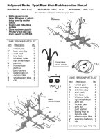
Hollywood Racks Sport Rider Hitch Rack Instruction Manual
Model HR1200 – 3 Bike, 2” rec. Model HR1210 – 3 Bike, 1 ¼” rec. Model HR1400 - 4 Bike, 2” rec.
Not to be used on any
trailer, fifth wheel or vehicle
being towed by another
vehicle
Weight Limit 45lbs/20 kg
per bike
3 bike maximum capacity
HR1200/1210, 4 bike max-
imum capacity on HR1400
3 BIKE VERSION PARTS LIST
Item Description Qty
A vertical post 2
B* base assembly 1
C short hook 2
D long hook 1
E left wheel holder 3
F right wheel holder 3
G pivot bolt 1
H receiver tube 1
I pivot nut 1
J pivot washers 2
K locking hitch pin 1
L security cable 1
M wheel support tube 4
R clip 1
4 BIKE VERSION PARTS LIST
Item Description Qty
A vertical post 2
B1 base assembly 1
B2 extension assy 1
C short hook 2
D long hook 2
E left wheel holder 4
F right wheel holder 4
G pivot bolt 1
H receiver tube 1
I pivot nut 1
J pivot washers 2
K locking hitch pin 1
L security cable 1
M wheel support tube 4
N* extension hardware 1
R clip 1
*see detailed drawing pg 4, Fig. 11a
A
Fig. 2
1
Pour instructions en Français, continuer aux pages 6 et 7.
Fig. 3
Features new
ratchet system
Assembly Instructions:
Tools Required: Two 8” adjustable
wrenches or equivalent, Phillips
screwdriver.
For ease of assembly, we suggest
that you use your vehicle’s hitch.
Step 1: Assemble Receiver Tube
to Base Assembly
1. Install your receiver tube H
into the hitch. Unlock hitch pin
K and insert it through hole in
the hitch and the rack. Then
tighten the lever H7 on the front of
the insert tube so the insert tube
will not move during assembly.
2. See Fig. 5 and 6: Gently insert
Base Assy B into the bracket of
Receiver tube H, aligning holes H3
with B2. The main beam can rest
on pin H5. There are two plastic
washers (B3) attached to
main beam B, please take care not
to accidentally scrape them off
during assembly. Insert pivot bolt
G with washer J through holes,
then place the other washer J on
end of bolt and hand tighten nut I.
3. Insert pin H6 through holes H4
and B4.Then install clip R through
the pin. The main beam will now be
in a fixed Horizontal position.
Tighten bolt G and nut I securely
with wrenches.
4. After tightening, remove clip R &
Pin H6 and rotate Main Beam B
into a folded (vertical) position.
Insert pin H6 through holes H2 to
check alignment. Main beam
should be able to rotate easily, but
not be too loose.
5. Remove pin H6 and rotate main
beam back to it’s horizontal position
to continue assembly.
Fig. 6
Fig. 5
Fig. 7: three bike base assembly
2
Step 2: Ins
tall Wheel Holders:
See Fig. 8: Rotate and remove L pins
From holes A. Rotate wheel tubes to a
horizontal position, then replace L pins
into holes B.
Slide wheel Holders E and F onto
wheel tubes as indicated below.
Fig. 8
Step 3: Install ratcheting frame hooks:
Slide long frame hook down vertical post facing vehicle.
Then slide short frame hook onto post, facing away from
vehicle. You should hear be able to hear the spring loaded
lever engaging the teeth on the post as shown in fig. 10a
Fig. 9
3
C
D
Fig 10a
Step 4: Installing extension
assembly on 4 bike model.
Slide extension assembly B1 into
base assembly B per Fig. 11. Align
holes and insert bolts through the
walls of the tubes (Fig.11b). The
square holes in the inner tube will
prevent the bolts from spinning, and
the bolt heads should be almost flush
with the outer tube. Install flat
washers, then lock washers and nuts
per Fig. 11c. Tighten nuts securely.
Repeat Steps 3 and 4 for installing
the wheel holders and frame hooks.
Note: The front square reflector cap
is attached with a Phillips head screw
below it, and should be mounted in
either the 2 bike or 4 bike
configuration.
Fig. 11
Fold up feature:
To fold up the main beam,
You must first fold down the
vertical post. Refer to Fig. 12:
Rotate and remove pin B, then
rotate the post (B) and replace
the pin in either holes C.
Now refer to Fig. 5: remove clip
R from pin H6, then remove pin
H6. Rotate main beam upward
and re-install pin and clip. See
Fig. 13a and 13b
Tilt
–
Down Feature:
For easy access to the rear
cargo door of your vehicle,
the Sport Rider can be tilted
down: First fold down vertical
Post as described in “Fold-up
feature”. Next refer to fig. 5:
Remove pin H5 from receiver
tube bracket and gently lower
the main beam down so it is
resting on the welded stop.
See Fig. 14
Fig. 11a
Fig. 11b
Fig. 11c
Fig. 12
Fig. 13a
Fig. 13b
4
Fig. 14
Step 5: Installing bikes on the rack
The bikes should be mounted from inside (1
st
bike) to
the outer most bike (3
rd
or 4
th
bike). See Fig. 16.
The bikes should always be positioned so that the lowest point on
the bike frame’s top tube is close to the vertical post (Fig. 17f).
The bike handlebars should be staggered (first bike’s handlebars
on passenger side, second bike’s handlebars on driver side, etc.
1. Lower both vertical posts as described earlier.
2. To adjust the first bike’s wheels trays, loosen the knobs and
slide wheel holders along the wheel support tube so that they are
positioned directly beneath each wheel.
Tighten knobs securely. Rotate the bike’s pedals so that the
vertical post can be raised and secured. Slide the ratcheting hook
down onto the frame (17f). Use the Velcro strap on the wheel
holder per Fig. 17d.
3. Adjust the wheel holders of the second bike and mount
to the rack in the same procedure as described above.
4. Raise and secure the outer vertical post for the 3
rd
or 4
th
bike.
5. If you have a 3 bike rack, follow the same procedure as you did
for the second bike.
6. If you have a four bike rack, position the third bike between the
outer vertical post and, adjust the wheel holders and secure the
bike to the rack with the frame hook and Velcro straps. For the
fourth bike, follow the same steps as you did for mounting the
second bike.
7. Be sure that the hooks are well supported on the bike’s
frame and the knobs securely pushing down on the bike’s
frame.
Tips for carrying woman’s bikes and bikes with slanted top
tubes: Adjust the wheel trays so that the hook will rest in
the bike frame’s top tube and seat tube, as shown in Fig.
17g and 17h.
Fig. 16
17g
17h
5
Instructions continued on back page
17f
17d
Hollywood Sport Rider SE. Porte-vélo pour atelage remorque.
HR1200- 3 Vélo, atelage 2” HR1210- 3 Vélo, atelage 1-1/4” HR1400- 4 Vélo, atelage 2”
Ne pas utiliser ce produit sur une remorque ou un véhicule qui est remorqué.
Limite de poids par vélo de 45lbs ou 20 kgs
Capacité maximum 3 vélos (HR1200/1210) 4 vélos pour le HR1400
VERSION 3 VELO: LISTE DE PIECES
Ref Description des pièces Quantité
A Poteau vertical 2
B* Assemblage Base 1
C Crochet court 2
D Crochet long 1
E Support roue gauche 3
F Support roue droite 3
G Boulon de pivot 1
H Tube pour l’attelage remorque 1
I Ecrou pour Boulon G 1
J Rondelles 2
K Chevilles de securité 1
L Cable de sécurité 2
M Tube de support pour roue 4
R Agrafe pour cheville anti-jeu 1
Assemblage et procédure d’installation
Outils nécessaire: 2 clefs à molettes de 8”ou équivalent, un tournevis Phillips
Pour une installation facile, utiliser l’attelage de votre véhicule
Etape 1: Assemblage du tube pour l’attelage et l’assemblage base
1. Installer le tube H dans l’attelage. Dé-verrouiller la cheville K et l’inserrer à travers l’attelage
sur le véhicule ET le tube pour attelage H. Ensuite serrer le levier H7 devant le tube pour
enlever le mouvement pendant l’assemblage.
2. Voir Fig.5 et 6. Inserrer l’assemblage base B dans H en alignant les trous H3 avec B2. Le tube
peut être posé sur la goupille H5. Inserrer le boulon G avec une rondelles J dans le trou H3 à
travers le tube B et la plaque de H, inserrer l’autre rondelle, installer l’écrou I et serrer
fermement.
3. Inserrer la goupille H6 dans les trous H4 et B4. Ensuite installer l’agraffe R sur et à travers H6.
La base B sera maintenant en position horizontal fixe. Serrer le boulon G et l’écrou I fermemnt
avec les 2 clefs.
4. Après avoir serré, enlever l’agraffe R et la goupille H6 et pivoter la base B en position
verticale. Inserrer la goupille H6 dans le trou H2 pour vérifier l’alignement. La base devrait
pivoter sans problèmes tout en restant serrer.
5. Enlever la goupille H6 et pivoter la base B dans sa position horizontale pour continuer
l’installation.
Etape 2: Installer les supports de roue.
See Fig. 8: Pivoter et enlever les goupilles L des trous A. Pivoter les tubes de supports de roue
horizontalement, inserrer les goupilles L dans les trous à travers les tubes de support de roue.
Glisser les support de roue E et F dans les tubes comme sur la Fig. 9
VERSION 4 VELO: LISTE DE PIECES
Ref Description des pièces
Quantité
A Poteau vertical 2
B1 Assemblage Base 1
B2 Assemblage d’extension 1
C Crochet court 2
D Crochet long 2
E Support roue gauche 4
F Support roue droite 4
G Boulon de pivot 1
H Tube pour l’attelage remorque 1
I Ecrou pour Boulon G 1
J Rondelles 2
K Chevilles de securité 1
L Cable de sécurité 2
M Tube de support pour roue 4
N* Materiel d’extension 1
R Agrafe pour cheville anti-jeu 1
Voir shema detaillé Pg4, Fig. 11a
6
Etape 3: Installer les crochets pour cadre
Glisser le long crochet D le long du poteau central, crochet vers le véhicule. Ensuite glisser le crochet court
C le long du poteau central, crochet vers l’exterieur ou l’arrière. Si vous avez un 3 velo, continuer à
installer les supports de roues et crochet vers l’arrière de l’ensemble comme sur Fig. 10.
Etape 4: Installation de l’extension pour le 4 Vélo.
Glisser l’extension B1 dans la base B comme Fig. 11. Aligner les trous sur les tubes (Fig. 11b). Le trou
carré à l’interieur de la paroie du tube interne, empêche le boulon de tourner, et la tête du boulon doit être
au même niveau que la paroie du tube. Installer les rondelles plates et écrous comme Fig. 11c. Serrer les
écrous fermements.
Répéter les étapes 3 et 4 pour installer les supports de roue et crochets.
Note: Le reflecteur carré est attaché avec une vis Phillips au dessous, et doit être présent en configuration 2 vélo ou 4 vélo.
Pliage du Sport Rider SE:
Plier d’abord les poteaux verticaux comme sur Fig. 12. Tourner et enlever la goupille B et la remettre dans
les trous C. Enlever l’agraffe R de la goupille H6 (Fig. 5) et enlever la goupille H6. Faire pivoter
l’ensemble vers le haut et re-installer goupille et agraffe (Fig. 13a et 13b).
Inclinaison du Porte-Velo Pour accés à la porte arrière.
Plier d’abord les poteaux verticaux, ensuite voir Fig. 5, enlever les goupilles H5 du tube pour attelage et
gentillement faire incliner le porte-vélo comme Fig. 14
Installation des vélos sur le Porte-vélo
Pré-positioner les supports de roues E et F à la distance du centre de chaque roue de chaque vélo. Pour
ajuster les supports de roues, deserrer les molettes, faire glisser les supports de roues le long des tubes
pour les supports de roues. Reserrer les molettes fermement (Fig 17a)
Pour monter le premier vélo vers le véhicule, le mât central peut être incliné Fig 16a-16d. Le guidon du
premier vélo devrait être du côté du conducteur. Toujours charger le vélo le plus petit d’abord (entre le
véhicule et le mât central).
Baisser les crochets sur le cadre et serrer les molettes fermement (Fig 17a-17e). Serrer les les sangles
des roués.Répèter pour le deuxième vélo (côté exterieur du mât). Continuer pareillement pour le
troisième (HR1200/1210) et quatrième vélo (HR1400 seulement).
Important: Pour les vélos femmes/ mixte ou avec cadre avec tube central incliné.
Ajuster les supports de roues de façon à ce que le crochet soit à l’intersection sur le cadre du tube
de selle et du tube central incliné (Fig 17h)
Vérifier Les choses suivantes avant de partir.
Molettes bien serrées pour les supports de roues et les crochets
Toutes les broches soient proprement inserrées et securisées.
Les sangles pour les roues soient bien attachées.
Chevilles, goupilles boulons rondelles et ecrous soient bien installées comme decrit ci-dessus.
Conduire doucement sur chaussée en mauvais état ou chemin de terre.
Important:
Le fabriquant de ce produit n’est pas responsible des dommages causés par le mauvais usage
de ce produit. C’est la responsabilité de l’utilisateur de s’assurer que le porte vélo
est monté proprement sur le véhicule et que les vélos soient proprement chargés sur
le porte vélo comme decrit dans ces instructions d’installation.
7
Limited Lifetime Warranty (effective January 1, 2008):
Hollywood Racks will warrant its car racks and accessories during the time that an original retail purchaser
owns the product subject to the exclusions and limitations of this warranty. Hollywood Racks will remedy
defects in materials and workmanship by repairing or replacing (at its option) a defective part without charge
for labor or parts. Hollywood Racks may elect (at its option) to issue a refund equal to the purchase price
paid for the product.
This warranty does not cover problems caused by normal wear and tear including (but not limited to)
weather, scratches, dents, rust, accidents, unlawful vehicle operation, misuse, abuse, neglect, theft,
unauthorized modifications, or unauthorized repair. No warranty is given for defects resulting in incorrect
assembly, incorrect installation onto the vehicle, installation on a “no fit” vehicle, incorrect attachment of
bicycles onto the rack, or overloading of the rack’s weight restrictions. This warranty terminates if the
original retail purchaser transfers the product to any other person.
If a product is believed to be defective, the original retail purchaser should contact either the original retailer
or Hollywood Racks directly at 800-747-4085 or at
Disclaimer of Liability: Repair or replacement of a defective product or the issuance of a refund or credit
(as determined by Hollywood Racks) is a purchaser’s exclusive remedy under this warranty. Damage to a
purchaser’s vehicle, cargo, bicycles and or to any other person is excluded. This warranty is expressly
made in lieu of any and all other express warranties, whether oral or written.
Hollywood Racks shall not be liable for any direct, indirect, consequential, incidental, special, punitive or
any other damages in connection with the purchase, use or handling of this product.
Some states do not allow the exclusion or limitation of consequential or incidental damages and the above
limitation may not apply to you. This warranty gives you specific legal rights and you have other rights, which
vary from state to state.
Hollywood Racks
12812 South Spring Street Los Angeles, CA 90061
(800) 747-4085 (310) 516-8600 Fax (310) 516-8955
Customer Service Hours: 8:00 AM- 3:00 PM Pacific Time M-F
www.hollywoodracks.com
made in Taiwan 1108 rev D
8
Double check before driving off:
Knobs are tight on all four wheel trays and both frame hooks.
All three retaining pins are properly inserted and secure
Wheel straps are fastened
Hitch pin is secure and hitch pin clip is installed
Drive slowly on bumpy or dirt roads