RYK-9244_6_8_ User Manual pptx
Bạn đang xem bản rút gọn của tài liệu. Xem và tải ngay bản đầy đủ của tài liệu tại đây (5.11 MB, 54 trang )
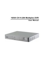
User Manual
16/ 8/ 4CH H.264 Multiplex DVR
VER.:2.0, P/N: R040199B
This symbol is intended to alert the user to the presence of unprotected “Dangerous voltage"
within the product's enclosure that may be strong enough to cause a risk of electric shock.
This symbol is intended to alert the user to the presence of important operating and
maintenance (servicing) instructions in the literature accompanying the appliance.
WARNING
TO REDUCE THE RISK OF FIRE OR ELECTRIC SHOCK, DO NOT EXPOSE THIS APPLIANCE TO RAIN
OR MOISTURE.
NOTE: This equipment has been tested and found to comply with the limits for a class digital device,
pursuant to part 15 of the FCC Rules. These limits are designed to provide reasonable protection
against harmful interference when the equipment is operated in a commercial environment. This
equipment generates, uses, and can radiate radio frequency energy and, if not installed and used
in accordance with the instruction manual, may cause harmful interference to radio
communications. Operation of this equipment in a residential area is likely to cause harmful
interference in which case the user will be required to correct the interference at ones own
expense.
Disposal of Old Electrical & Electronic Equipment (Applicable in the European
Union and other European countries with separate collection systems)
This symbol on the product or on its packaging indicates that this product shall not be treated as household
waste. Instead it shall be handed over to the applicable collection point for the recycling of electrical and
electronic equipment. By ensuring this product is disposed of correctly, you will help prevent potential
negative consequences for the environment and human health, which could otherwise be caused by
I
inappropriate waste handling of this product. The recycling of materials will help to conserve natural
resources. For more detailed information about recycling of this product, please contact your local city office,
your household waste disposal service or the shop where you purchased the product.
II
All the safety and operating instructions must be read before the unit is operated.
•
Make sure to switch the power off before you install the DVR.
•
There is the danger of an electric shock if the DVR is opened by an unqualified service
engineer or installer.
•
Avoid using the DVR outside of the reference temperature and humidity indicated in the
specification.
•
Avoid exposing the DVR to violent movement or vibration.
•
Do not use or store the DVR in direct sunlight or near to any source of heat.
•
Do not place any object into the holes used for air circulation.
•
Always use the DVR in a well ventilated location to prevent overheating.
•
Risk of explosion if battery is replaced by an incorrect type.
•
Dispose of used batteries according to the instructions.
III
TABLE OF CONTENTS
Chapter 1 FEATURES 1
Chapter 2 MAIN MENU OPERATION 2
2.1 Quick Setup 2
2.2 Network Remote Instructions 5
2.3 Playback Mode 6
2.4 PTZ Mode 7
Chapter 3 INSTALLATION 9
3.1 System Configuration – 16CH 9
3.2 System Configuration – 8CH 9
3.3 System Configuration – 4CH 10
10
3.4 Hard Disk Installation 10
Chapter 4 BASIC OPERATION and MENU SETUP 12
4.1 Main Menu Setup 12
4.2 Record Setup 14
4.3 Event Setup 16
4.4 Schedule Setup 20
4.5 Camera Setup 22
4.6 Account Setup 22
4.7 Network Setup 24
4.8 PTZ & RS-485 Setup 31
4.9 System Setup 32
4.10 Utility Setup 39
4.11 Diagnostic 40
Chapter 5 SEARCH & BACKUP 41
5.1 Search Setup 41
5.2 Backup Setup 44
Chapter 6 SPECIFICATION 45
Chapter 7 NETWORK SURVEILLANCE 47
7.1 Remote Connection 47
7.2 Remote Backup 49
The author assumes no responsibility for any errors or omissions that may appear in this
document nor does the author make a commitment to update the information herein.
IV
Chapter 1 FEATURES
Two USB ports (for mouse usage and backup).
Dual streaming enhances the speed of network transmission
Built-in VGA output & Optional HDMI output up to 1280x1024 resolution
Individual setup of resolution, frame rate and video quality for each channel
Still image snapshot
AVI converter with time stamp
H.264 compression ideal for saving HDD space
Real time live display
Live display, record, backup, playback and network access simultaneously
Picture-in-picture monitoring and 2X to 8X digital zoom display
Control Methods: front panel, USB mouse, IR remote controller, client viewer
Intuitive GUI for easy configuration and menu driven operation
Pan / Tilt / Zoom camera control
Data backup: USB devices, network and DVD-RW
Event triggered with email notification: motion detection, alarm, video loss
Supports Internet Explorer with same GUI as DVR site
Multi-language OSD
Central Management System (CMS)
3G/ GPRS mobile phone monitoring
1
Chapter 2 MAIN MENU OPERATION
2.1 Quick Setup
Graphic Icons
Resting the cursor on this icon will bring up the four (Main Menu/ Search/
Backup/ PTZ) menu icons.
MAIN MENU.
SEARCH SETUP.
BACKUP.
PTZ CONTROL.
Turn On/Off recording.
PLAYBACK
Resting the cursor on this icon will bring up five (PAUSE/ PIP/ ZOOM/
AUTO SEQ/ LOCK) display icons.
PAUSE, to pause LIVE image
PIP, picture in picture
ZOOM, 2X to 8X digital zoom in / out the screen size
AUTO-sequence
LOCK, activate the key lock.
Full screen display, multiple clicking to switch channels
Quad display.
9CH Split-screen display (available only to 8/ 16CH DVR).
13CH Split-screen display (available only to 16CH DVR).
2
16CH Split-screen display (available only to 16CH DVR).
3
GUI Hints and Tips
Recording is on
Number represents the current selected LIVE audio channel
(
available to
8/ 16CH DVR and option to 4CH DVR).
Live Audio is off
Motion detected on the channel
Sensor triggered on the channel
Video loss detected on the channel
USB device detected
DVR has been connected onto the Internet.
AUTO-SEQ is on
FREEZE is on, screen is frozen
LOCK is on
PTZ control is on
Shows the current hard disk space used-up (99% means that the HDD
space has been used up 99%, and the remaining HDD space is 1%)
Current time which is used when providing the conversion of AVI files is
shown on the bottom lower right of each DVR screen.
99%
4
2.2 Network Remote Instructions
Same user and DVR-site interface, the only difference is network toolbar which is
situated on the lower bottom right.
Icon Description
/
Low Video Quality (LQ)
High Video Quality (HQ)
* Please refer to 4.7.2 HTTP setup
/
Full Screen
Record
Capture Image
Record and captured files storage path settings
Open / Close this tool bar
5
2.3 Playback Mode
Playback – Quick Function Icon
Press「 / 」button to Fast Rewind
Speed : 2x, 4x, 8x, 16x, 32x, 64x
Press「 / 」button to Fast Forward
Speed : 2x, 4x, 8x, 16x, 32x, 64x
/
Press「PLAY」/ 「 」button to Play/ Pause Playback
「 / SLOW」slow playback
Speed : 1/2x, 1/4x, 1/8x
「 / 」stop playback
Playback channel by channel with snap shot display
Full screen display
Quad display
9CH Split-screen display (available only to 8/ 16CH DVR)
16CH Split-screen display (available only to 16CH DVR)
Zoom in video image
Snap shot image
6
2.4 PTZ Mode
PTZ – Remote Controller Control
/ SLOW Move PTZ up.
/ Move PTZ down.
/ Move PTZ to the left.
/ Move PTZ to the right.
ZOOM + PTZ zoom-in.
ZOOM - PTZ zoom-out.
FOCUS + PTZ focus-in.
FOCUS - PTZ focus-out.
IRIS + PTZ iris-open.
IRIS - PTZ iris-close.
TOUR Activate PTZ pre-set tour.
*
PRESET + NUMBER To save a preset location
Press PRESET and a number key. DVR will save the current location.
PLAY + NUMBER To go to a preset location
Press PLAY and a number key. DVR will move to the preset location.
ZOOM Set current PTZ location as the end of the line-scan.
*
PIP Set current PTZ location as the start of the line-scan.
*
FREEZE Activate line-scan.
*
*
:
Different brands of PTZ protocol sometimes may not be 100% compatible with each
other. Therefore, these functions may not be applicable.
7
PTZ – Quick Function Icon
Exit PTZ Mode and back to the LIVE mode
Preset number N. (1~64)
Go to preset number N.
Set current PTZ location at preset number N.
[TOUR] icon, click to activate preset tour
Same as [PIP]. Set current PTZ location as the starting point of the line-
scan.
Same as [FREEZE]. Activate line-scan.
Same as [ZOOM]. Set current PTZ location as the ending point of the
line-scan.
To move PTZ in 360°
PTZ zoom in or PTZ zoom out.
PTZ focus in or PTZ focus out.
PTZ IRIS open or PTZ IRIS closes.
8
Chapter 3 INSTALLATION
3.1 System Configuration – 16CH
3.2 System Configuration – 8CH
9
3.3 System Configuration – 4CH
3.4 Hard Disk Installation
First, remove the HDD holder from the DVR machine (Pic 1).
(PIC 1)
Lock the HDD holder symmetrically onto both sides of the HDD (Pic 2, Pic 3).
(Pic 2) (Pic 3)
10
Insert the SATA cable and power cable onto the SATA HDD (Pic 4).
(Pic 4)
Lock the HDDs onto the DVR machine (Pic 5).
(Pic 5)
Insert the SATA cables into the sockets on the main board (Pic 6). Make sure that the
HDD1 cable has been properly inserted into HDD1 socket. Now, the installation has been
completed (Pic 7).
(
Pi c 6
)
(
16CH DVR
)
(4/ 8CH DVR)
(Pic 7)
11
Chapter 4 BASIC OPERATION and MENU SETUP
4.1 Main Menu Setup
To enter the main menu and setup the DVR, please log-in account and enter user
password. The default password of the administrator is “123456”. Please refer to “4.6
Account Setup” for related setup of other log-in users.
Main Menu – Mouse Control
(Right mouse click to enter Quick Setup Menu)
Switch between capital and small letters.
/
Switch between numbers and letters.
Press to cancel the setup, and re-choose the login account.
Delete the last character.
Enter to identify the password. It will enter the setup menu if the password
is verified.
Space key
12
Main Menu – Remote Controller and Front Pannel Control
(Click MENU button to enter Quick Setup Menu )
Switch to different options under one item
Switch to different items
MENU Press to confirm setup (OK)
ESC Press to cancel setup (CANCEL)
ENTER Enter the menu, or display virtual keyboard
13
4.2 Record Setup
Item Description
HDD FULL Select STOP to stop recording or OVERWRITE to reuse the HDD when
HDD is full.
[Stop]
:
Stop Recording
[Overwrite]
:
Start to overwrite beginning from the oldest data of HDD,
and continue to record.
OSD Position X Set time stamp of OSD position X
OSD Position Y Set time stamp of OSD position Y
OSD Position Setup OSD position time stamp setup
Video Preservation (Hours)
Information stored within the HDD is preserved for only a specified
length of time.
Quality & Frame Rate
Setup…
Setup the quality and frame rate for each channel under normal
recording and event recording type.
14
4.2.1 Quality & Frame Rate Setup
*
Number of “Auto” means the DVR processing ability. Recording data depends on “FPS”.
Ex: If channel 1 to channel 8 set to 15 FPS, the sum will be 120 FPS. (8 x 15 = 120)
Item Description
View Normal / View Event Setup resolution, quality and FPS separately for different record type.
No. Check/ Uncheck the box will enable/ disable recording of that channel.
Resolution Choose record resolution, this value will be used by each channel.
Quality Choose from Below Basic / Basic/ Normal/ High/ Highest.
FPS Choose recording frame rate (1~30).
Auto The maximum recording frames available by the average distribution of
each channel.
15
4.3 Event Setup
Item Description
Motion Setup Enter to set up motion detection
Sensor Setup Enter to set up sensor detection
4.3.1 Motion Setup
16
17
Item Description
Alarm Duration(Seconds) Alarm duration time (1~60 seconds).
Motion Popup Check the box to Enable/ Disable popup screen function for all channels.
When motion is detected in LIVE mode, the detected channel image will
popup in full screen display.
Enable Check the box to Enable/ Disable motion detection for each channel.
Sensitivity Drag the bar or press ◀ ▶ to set up Sensitivity from value 0 to 10 for
each channel. The lower value you set lower the sensitivity it will be
Motion Area Setup Enter to setup motion detection area
Apply to All Set all the channels to the same setting.
4.3.1.1 Motion Area Setup
There are partitions in motion detection area (22x15 blocks). Under initializing status,
motion detection area is in the entire screen. Red colored area is undetected; yet the
detected area is transparent.
Item Description
Mask Mouse Selection Select to mask the mouse selected area.
All Area Detection Select all the images as motion detection area.
Mask All Area Cancel all motion detection images on the screen.
Continue Continue setup.
Exit & Save Save setup and exit setup page.
Exit & Discard Cancel setup and exit setup page.
18
4.3.2 Sensor Setup
Item Description
Alarm Duration(Seconds) Alarm duration time (1~60 seconds).
Sensor Popup Check the box to Enable/Disable popup screen function for all channels.
When Sensor is detected in LIVE mode, the detected channel image will
pop up in full screen display.
Sensor Polarity Click or press ▼ to select between HIGH/ LOW voltage for triggering
sensor detection or OFF to turn off polarity for each channel
Low Polarity:Sensor has not been triggered. When connected, sensor
will be turned on (N.O.→N.C.).
High Polarity : Sensor has been triggered. When connected, sensor
status will be turned off (N.C.→N.O.).
Off:Sensor is deactivated, and will not be turned on/off.
All off
Set all sensors polarity to off.
All Low Set all sensors p
olarity to low level.
All High Set all sensors p
olarity to high level.
19
4.4 Schedule Setup
Apart from manual recording, you can also setup the recording time by weeks and
schedule recordings include: normal, motion detection, and sensor detection.
Item Description
Page Click or press ▼ to select Page. Each page provides 10 schedules for
setup. 5 pages in total.
Holiday Setup Enter to setup holiday, maximum up to 50 days.
View Event Setup View Normal/ Motion / Sensor Setup.
20