- Trang chủ >>
- Khoa Học Tự Nhiên >>
- Vật lý
Si and siox nanostructures formed via thermal evaporation
Bạn đang xem bản rút gọn của tài liệu. Xem và tải ngay bản đầy đủ của tài liệu tại đây (682.76 KB, 7 trang )
Si and SiO
x
nanostructures formed via thermal evaporation
Yong-jun Chen
*
, Jian-bao Li, Jin-hui Dai
Department of Materials Science and Engineering, State Key Laboratory of New Ceramics and Fine Processing, Tsinghua University,
Beijing 100084, China
Received 18 April 2001; in ®nal form 13 June 2001
Abstract
Various Si and SiO
x
x 1 to 2 nanostructures were formed via a thermal evaporation method of heating pure silicon
powder at 1373 K under Ar ¯ow. An alkali-treated quartz glass plate coating with catalyst precursor of a FeNO
3
3
aqueous solution was used as substrate. The product exhibited morphologies of ®st-capped SiO
x
®bers (Si-core), tree-like
SiO
x
nano®bers and tadpole-like SiO
x
nano®bers in dierent areas of the substrate. The dierent local temperature
gradient, concentration of silicon vapor and silicon oxide vapor, and also the substrate surface condition were suggested
to be responsible for the versatile morphologies of the products. Ó 2001 Elsevier Science B.V. All rights reserved.
1. Introduction
Silicon and silica nanostructures have attracted
considerable attention because of their unique
properties and promising application in meso-
scopic research, nanodevices, opto-electronics
devices [1±4]. For instance, the brightness of blue
light emitted by mesoporous silica ®bers is hun-
dred times than that produced by porous silicon
[5], making silica ®bers attractive for use as high-
intensity light sources [6,7], near-®eld optical mi-
croscopy probes and hosts to lasting materials
and waveguides [8]. Previous researchers have
reported the synthesis of crystalline silicon nano-
wires with an out-layer of amorphous silicon
oxide [5,9±11]. SiO
1:4
nanowires [12] and amor-
phous silica nanowires [13] have also been pre-
pared recently. It is of interest to note that silicon
oxide may form some novel morphology such as
silica `nano¯ower' [14], radial patterns of car-
bonated silica ®bers [15], silica nanowire `bundles'
and silica `nanobrushes' [16] under dierent con-
ditions. In this Letter, some interesting self-as-
sembled Si and SiO
x
nanostructures were formed,
which consist of ®st-capped SiO
x
®bers (Si-core),
tree-like SiO
x
nano®bers and tadpole-like SiO
x
nano®bers.
2. Experimental
A conventional tube furnace holding an alu-
mina tube (24 Â 800 mm
2
) was employed to syn-
thesize the nanostructures. An alumina boat
loaded with pure silicon powder using as silicon
source was placed in the middle part of the tube.
Another alumina boat holding a catalyst-coated
substrate (20 Â 10 Â 1:5mm
3
) was placed next to
the ®rst boat with a distance of 10 mm on the
downstream side of the ¯owing argon. This set-up
is similar to that reported in [17]. The catalyst-
coated substrate was prepared as follows. A quartz
31 August 2001
Chemical Physics Letters 344 (2001) 450±456
www.elsevier.com/locate/cplett
*
Corresponding author. Fax: + 86-10-6278-2753.
E-mail address: (Y j. Chen).
0009-2614/01/$ - see front matter Ó 2001 Elsevier Science B.V. All rights reserved.
PII: S 0 0 0 9 - 2 6 1 4 ( 0 1 ) 00742-4
glass substrate was ultrasonically cleaned in dis-
tilled water, followed by etching in a heated 6M
NaOH solution ($353 K) for 15 min. After
leaching in distilled water and ethanol and drying
in air, the substrate was quickly dipped in a
0.005M ferric nitrate FeNO
3
3
aqueous solution
to obtain a thin catalyst ®lm.
Before heating, the furnace was ¯ushed with
pure argon ¯ow (150 sccm) for 15 min. It was then
heated to 1373 K at a rate of 20 K/min and held
for 30 min, then cooled to room temperature un-
der an constant argon ¯ow (30 sccm). A thin layer
of brown substance was found depositing on the
substrate. As-grown samples were characterized by
FE-SEM (JSM-6301F, 5±20 kV), TEM (JEM-
200CX, 200 kV), HRTEM (JEM-2010F, 200 kV)
and EDS(X) attached with SEM and HRTEM
(Link ISIS-300), respectively.
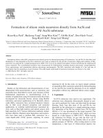
Fig. 1. (a) Zone distribution diagram of the substrate. SEM images of the products are shown in b±j. (b) Web-like ®bers formed in
zone A. (c) A closer view showing a ®st-like object-capped ®ber. (d) A tree-like object consists of a Si rod and SiO
x
nano®bers
generated in zone B. (e) The product consists of numerous tadpole-like objects created in zone C. (f) Magni®ed image of the samples
presented on the left side of e. (g) Magni®ed image of the samples presented on the right side of e. (h) Product generated in another area
of zone C. (i) A magni®ed image of h. (j) Products presented in another area of zone C.
Y. Chen et al. / Chemical Physics Letters 344 (2001) 450±456 451
3. Results
SEM observation shows that the as-grown
samples consist of ®brous substance and exhibit
dierent morphologies in dierent zones of the
substrate. Generally the products can be divided
into three types: ®st-capped web-like ®bers, tree-
like ®bers and tadpole-like ®bers. And the sub-
strate was correspondingly divided into three
zones (indicated as A, B and C), as shown in Fig.
1a. Fig. 1b shows that the product in Zone A
consists of web-like ®bers with diameters of
40±250 nm and lengths of tens to hundreds of
micrometers. Careful observation shows that, in
most cases, each ®ber has a ®st-like object attached
at one end, which looks like a long arm with a
®ngers-clenched hand (Fig. 1c). EDS reveals the
composition of these ®bers and ®st-like objects are
Fig. 1. (Continued)
452 Y. Chen et al. / Chemical Physics Letters 344 (2001) 450±456
SiO
x
x 1 to 2. The product in zone B is shown
in Fig. 1d, taking the shape of a tree. EDS indi-
cates that it consists of a Si stalk ($3 lm length,
380 nm diameter) and SiO
x
nano®bers branches
($3 lm length and 70±230 nm diameter). While,
the product in zone C is in the form of tadpoles
with dierent length (Fig. 1e). Figs. 1f and 1g show
that the tadpoles on the left and right side of zone
C have lengths of 15±30 and 30±70 lm, respec-
tively. At the same time, the ®bers in each `tadpole'
coalesced together and formed a bundle (referred
to as `nano®ber-bundle' hereafter) with disordered
growth direction. Generally, a Si rod links a SiO
x
nano®ber-bundle and a small particle (Fe catalyst
by EDS), which can be seen clearly from Fig. 1h
(as can also be observed vaguely in Figs. 1f and
1g). The higher-magni®ed images further con-
®rmed this structure, that is, numerous SiO
x
nano®bers extruded from a single Si rod (Figs. 1i
and 1j).
A very long nano®ber with diameter of $50 nm
formed in zone A is partly shown in Fig. 2a. The
selected area electron diraction (SAED) pattern
(inset the Fig. 2a) indicates that it is a crystalline Si
nano®ber. As shown in Fig. 2b, TEM shows that
the product in zone C exhibits a structure of
branched SiO
x
nano®bers grown from a Si rod,
which agrees with the SEM result mentioned
above. However, the number of nano®ber is re-
duced due to the later processing, e.g., the prepa-
ration of TEM sample. The higher-magni®ed
image (Fig. 2c) clearly shows a diversity of con-
trast between rod and nano®bers, which reveals
the dierence of composition between them (Si rod
Fig. 2. TEM images of (a) a Si nano®ber formed in zone A. The inset is the SAED pattern, indicating it is a crystalline Si nano®ber. (b)
A sample formed in zone C, showing branched SiO
x
nano®bers grown from a Si rod. (c) Magni®ed image of b, showing apparent
bubbles formed next to the tip of Si rod. (d) The nano®bers in the middle part of a nano®ber-bundle formed in zone C. The inset is the
SAED pattern, indicating they are amorphous.
Y. Chen et al. / Chemical Physics Letters 344 (2001) 450±456 453
and SiO
x
nano®bers). Fig. 2d shows that the
nano®bers in the middle part of a nano®ber-bun-
dle are self-aligned and have typical diameters of
20 nm. The SAED pattern (inset the Fig. 2d)
proved that they are amorphous SiO
x
nano®bers.
HRTEM image (Fig. 3a) further indicates that
the Si nano®ber in zone A has a crystalline Si-core
and an amorphous SiO
x
outer shell. The lattice
distance of the crystalline core is measured to be
0.31 nm, which is equal to the spacing of the
{1 1 1} planes of Si. EDX also indicates that the
core and the outer shell contain Si and SiO
x
, re-
spectively. It seems that the result of EDX is dif-
ferent from that of EDS. However, they agree well
with each other because EDS (attached with SEM)
could merely analyze the composition of the
sample surface (SiO
x
shell), whereas EDX (at-
tached with HRTEM) can further analyze the
composition from surface to the deep body (from
SiO
x
shell to Si-core). The nano®bers of the
Fig. 3. HRTEM images of (a) a Si nano®ber formed in zone A, showing a structure of crystalline Si-core sheathed with amorphous
SiO
x
layer. (b) A SiO
x
nano®ber in the middle of a nano®ber-bundle formed in zone C, indicating an amorphous state.
454 Y. Chen et al. / Chemical Physics Letters 344 (2001) 450±456
nano®ber-bundles in zone C, however, are com-
pletely non-crystalline SiO
x
nano®bers, which are
proved by EDX and HRTEM (Fig. 3b) and also
agree with the result of SAED.
4. Discussion
The various structures of the products re¯ect
the dierence of growth condition in dierent
zones (zone A, B, C). Firstly, the dierent tem-
perature gradient from zone A to C is responsible
for the diversity of ®ber-diameter by in¯uencing
the nano®ber growth rate. In our experiments, the
order of temperature gradient is zone A > zone
B > zone C. Since the largest temperature gradi-
ent in zone A results in the highest nano®ber
growth rate, relative thick ®bers are developed (as
seen in Fig. 1b). While the smallest temperature
gradient in zone C causes the formation of relative
thin nano®bers. In zone B, due to an intermediate
temperature gradient, a moderate growth rate re-
sults in the intermediate diameter of the product.
Secondly, the competitive growth between Si
®bers (or rods) and SiO
x
nano®bers causes a dif-
ferent structures of the product. Here, silicon oxide
vapor is probably generated by the reaction of
silicon vapor and the silica substrate at high tem-
perature, which is consistent with the supposition
by Zhu et al. [6,14]. However, Yu et al. [5] assumed
that amorphous state formed might be related to
the low temperature and short reaction time.
However, the real reason is not very clear up to
now. In zone A, the highest concentration of sili-
con vapor generated due to the shortest distance
from silicon source. On the other side, the con-
centration of silicon oxide vapor is quite small
because the silicon oxide vapor generated in this
area may mainly ¯ow o the outlet by Ar ¯ow.
Therefore, as mentioned above, Si sub-micrometer
®bers sheathed with a thin layer of amorphous
SiO
x
formed. In zone C, however, the concentra-
tion of silicon vapor is quite low due to the con-
sumption in zones A and B, while the
concentration of silicon oxide vapor is quite high
due to the additional accumulation of that gener-
ated in zones A and B. Therefore, a structure of
numerous SiO
x
nano®ber attaching to a short and
thin Si rod is developed. The product in zone B
presents an intermediate morphology, namely a
tree-like structure consisting of a Si rod and SiO
x
®bers.
Thirdly, the surface condition of the substrate
may also have an important eect on the structure
of the product. As depicted in Fig. 4, the treat-
ment with alkali solution (NaOH) made the sur-
face of the quartz substrate rough and porous
(Fig. 4a). Hence, major catalyst aggregated within
these holes (Fig. 4b) and only minor catalyst re-
mained on the planar surface. In zone A, the
highest concentration of the silicon vapor results
in the long web-like ®bers. However, the catalyst
resided on the surface has a smaller size and that
aggregated within holes has a larger size, which
leads to the thin and thick diameter ®bers, re-
spectively (as seen in Fig. 1b). In zone C, the
smaller concentration of silicon vapor caused
h
(d)
(c)
(b)
(a)
Fig. 4. A schematic model for Si rods and SiO
x
nano®bers
growth. (a) Surface condition of a treated quartz substrate. (b)
Si rods grown in holes via a VLS process. (c) SiO
x
nano®bers
grown from Si rods. (d) Lodging of Si rods and SiO
x
nano®bers
with disordered orientation. Sometimes Si rod has a small
catalyst plate attached.
Y. Chen et al. / Chemical Physics Letters 344 (2001) 450±456 455
fewer silicon rods. Due to the `con®ne eect' of the
holes, only after these Si rods protruded out of the
holes can the SiO
x
nano®bers formed at the up
ends of Si rods.
Vapor±liquid±solid (VLS) [12,13], solid±liquid±
solid (SLS) [18], oxide-assisted (OA) [19] etc., were
used to explain the growth mechanism of silicon
nanowires and silica nanowires. In our experi-
ments, Si ®bers sheathed with SiO
x
shells formed
in zone A should grow via an OA model because
each ®ber is generally attached by a SiO
x
particle
(®st-like object), which is similar to the result of
Zhang et al. [20]. Si rods formed in zone C should
grow via a VLS mechanism (Fig. 4b), which can be
veri®ed by the apparent bubbles formed next to
the tips of Si rods (Fig. 2c). EDS also reveals the
aggregation of catalyst Fe at the tips of Si rods.
However, the growth of SiO
x
nano®bers seems to
be dominated by a vapor±solid (VS) process (Fig.
4c), because the catalyst aggregated at the tip of Si
rod seems to be merely involved in the nucleation
and initial ®ber growth. Subsequently, nano®bers
grew by absorbing the growth units from silicon
oxide vapor and the growth process no longer in-
volved liquid phase. Yet, the reason of a small
object attaching to the other end of Si rod is not
clear. We suppose that the growth of the products
(in zone C) within holes is similar to the growth of
trees within pits (Fig. 4c). Once the length of the
nano®ber-bundles reaches to a certain value, the
nano®ber-bundles fall down when they are sub-
jected to some unbalanced force such as Ar ¯ow,
gravity force, thermal shock and etc. (Fig. 4d).
Moreover, the falling directions are at random.
Therefore, Si rod attached by a small object is
analogous to the tree-root attached by soil parti-
cle; except the soil particle is substituted by the
small catalyst particle remained within holes.
5. Conclusion
Si and SiO
x
nanostructures of ®st-capped ®bers,
tree-like and tadpole-like objects were generated
by heating pure silicon powder at 1373 K under Ar
¯ow. SEM, TEM, HRTEM and EDS(X) reveal
that the dierent local temperature gradient, con-
centration of silicon vapor and silicon oxide vapor
in dierent areas result in the versatile structures of
Si and SiO
x
. In addition, the treatment with alkali
solution, which leads to a rough substrate surface
with numerous holes, also plays a key role in the
formation of various morphological Si and SiO
x
nanostructures.
Acknowledgements
The authors would like to thank the support
from National Natural Science Foundation of
China (NSFC, Grant No. 59972104).
References
[1] S. Mann, G.A. Ozin, Nature 382 (1996) 313.
[2] W. Wesh, Nucl. Instrum. Meth. Phys. Rev. B 116 (1996)
305.
[3] A. Katz, M.E. Davis, Nature 403 (2000) 286.
[4] C.T. Kresge, M.W. Leonowicz, W.J. Roth, J.C. Vartuli,
J.S. Beck, Nature 359 (1999) 710.
[5] D.P. Yu, Q.L. Hang, Y. Ding, H.Z. Zhang, Z.G. Bai et al.,
Appl. Phys. Lett. 73 (1998) 3076.
[6] Y.Q. Zhu, W.B. Hu, W.K. Hsu et al., Adv. Mater. 11
(1999) 844.
[7] A.P. Alivisatos, Science 271 (1996) 933.
[8] F. Marlow, M.D. Mcgehee, D. Zhao et al., Adv. Mater. 11
(1999) 632.
[9] J. Hu, T.W. Odom, C.M. Lieber, Acc. Chem. Res. 32
(1999) 435.
[10] S.T. Lee, N. Wang, Y.F. Zhang, Y.H. Tang, MRS Bull. 8
(1999) 36.
[11] J.D. Holmes, K.P. Johnston, R.C. Doty, B.A. Korgel,
Science 287 (2000) 1471.
[12] C.H. Liang, L.D. Zhang, G.W. Meng, J. Non-Cryst. Solids
277 (2000) 63.
[13] X.C. Wu, W.H. Song, K.Y. Wang, T. Hu et al., Chem.
Phys. Lett. 336 (2001) 53.
[14] Y.Q. Zhu, W.K. Hsu, M. Terrones, N. Grobert et al., J.
Mater. Chem. 8 (1998) 1859.
[15] Z.J. Zhang, G. Ramanath, P.M. Ajayan, D. Goldberg, Y.
Bando, Adv. Mater. 13 (2001) 197.
[16] Z.L. Wang, R.P. Gao, J.L. Gole, J.D. Stout, Adv. Mater.
12 (2000) 1938.
[17] Q. Gu, H.Y. Dang, J. Cao, S.S. Fan et al., Appl. Phys.
Lett. 76 (2000) 3020.
[18] H.F. Yan, Y.J. Xing, Q.L. Hang, D.P. Yu et al., Chem.
Phys. Lett. 323 (2000) 224.
[19] Y.F. Zhang, Y.H. Tang, N. Wang, S.T. Lee et al., J. Cryst.
Growth 197 (1999) 136.
[20] Z. Zhang, X.H. Fan, L. Xu, C.S. Lee, S.T. Lee, Chem.
Phys. Lett. 337 (2001) 18.
456 Y. Chen et al. / Chemical Physics Letters 344 (2001) 450±456