- Trang chủ >>
- Khoa Học Tự Nhiên >>
- Vật lý
Surface modified silicon nano channel for urea sensing
Bạn đang xem bản rút gọn của tài liệu. Xem và tải ngay bản đầy đủ của tài liệu tại đây (777.09 KB, 6 trang )
Sensors and Actuators B 133 (2008) 593–598
Contents lists available at ScienceDirect
Sensors and Actuators B: Chemical
journal homepage: www.elsevier.com/locate/snb
Surface-modified silicon nano-channel for urea sensing
Yu Chen, Xihua Wang, Mi Hong, Shyamsunder Erramilli, Pritiraj Mohanty
∗
Department of Physics, Boston University, 590 Commonwealth Avenue, Boston, MA 02215, United States
article info
Article history:
Received 18 December 2007
Accepted 28 March 2008
Available online 8 April 2008
Keywords:
Nano-channel
Urea
Biosensor
Lithography
abstract
Silicon nano-channels have been surface functionalized with the enzymeurease for biosensor applications
to detect and quantify urea concentration. The device is nanofabricated from a silicon-on-insulator (SOI)
wafer with a top down lithography approach. The differential conductance of silicon nano-channels can
be tuned for optimum performance using the source drain bias voltage, and is sensitive to urea at low
concentration. The experimental results show a linear relationship between surface potential change and
urea concentration in the range of 0.1–0.68 mM. The sensitivity of our devices shows high reproducibility
with time and different measurement conditions. The nano-channel urea biosensor offers the possibility
of high quality, reusable enzyme sensor array integration with silicon-based circuits.
© 2008 Elsevier B.V. All rights reserved.
1. Introduction
Since the concept of ISFET (ion sensitive field-effect transistor)
was first introduced in biosensor applications by Bergveld [1],ithas
attracted a lot of interest among both experimentalists and theo-
rists [2–6]. The surface of the gate of the FET device can be modified
with sensing molecules like antibody or antigen, and has the poten-
tial for serving as a highly efficient immunological sensor with the
required specificity and sensitivity [7]. When antigen or antibody in
the test solution reacts with the sensing molecules on the surface,
any change in the charge state or surface potential leads to mod-
ulations of the conductance channel of the FET device. Thus the
concentration of the test molecules can be extracted by the con-
ductance or current measurement of the device. The measurement
of the immunological reaction is limited by the sensor response and
also ionic strength and pH of the test sample [8].
For potential clinical applications, an enzyme FET (ENFET),
which is a pH-based ISFET has been developed [8,9]. Glucose
sensors, and urea sensors are among the best-known biosensors
for widespread clinical applications. Traditional enzyme-linked
immunosorbent assay (ELISA) [10] measure the spectrum of the
enzyme-catalyzed products and require large volume of the sample
solution and thus decrease the sensitivity of the device. The ENFET,
especially micro and nanoscale FET, does not need large volume of
the solution and can provide fast and high sensitive detection of
target molecules.
Semiconductor nano-channels, such as carbon nanotubes
(CNTs) and silicon nanowires (SiNWs), have been studied intensely
∗
Corresponding author. Tel.: +1 617 352 4815; fax: +1 617 353 9393.
E-mail addresses: , (P. Mohanty).
for their extraordinary electrical, mechanical and optical char-
acteristics [11–13]. These characteristics have been used for
ultrasensitive biosensor applications [8,14]. Taking the advantage
of large surface-to-volume ratio, their electronic conductance may
even be sensitive enough to detect single molecule binding to the
surface. Most of the existing studies based on a bottom–up fabri-
cation approach are difficult to integrate into the manufacture of
complex sensing circuits. Fabrication of silicon nanowires with the
top down approach [15,16], based on standard semiconductor pro-
cesses, offer the promise of manufacturability and scalability for
mass production. Thus, field effect devices, combining nanotech-
nology, offer the possibility to produce high-performance, low-cost
biosensors.
Here we demonstrate the silicon nanowires, surface functional-
ized with enzyme (urease), as a field-effect enzyme biosensor. In
the differential conductance measurements, the device shows high
sensitivity to the local change in hydrogen ion concentration pro-
duced by the enzymatic reaction, i.e. essentially a “local” pH change.
We note that pH is usually defined as an inherently equilibrium
concept. The FET sensor senses the change in the surface potential
due to a change in concentration of hydrogen ions near the surface
of the sensor. To the extent that the time scales of measurement
are kept slow compared to the time scale of exchange of hydro-
gen ions, the surface potential can still be linked to an effective
pH. The sensitivity of the device response to the urea is demon-
strated down to 0.1 mM. While the device can be made sensitive
to still lower concentrations, this limit is sufficient for the clinical
applications, which require operation in the 0.1–1 mM range. The
calibrated surface potential change introduced by the reaction has
a linear range for urea concentration between 0.1mM and 0.68 mM.
Our silicon wire FET sensor shows very good stability. The depen-
dence of the differential conductance on urea concentration varies
0925-4005/$ – see front matter © 2008 Elsevier B.V. All rights reserved.
doi:10.1016/j.snb.2008.03.033
594 Y. Chen et al. / Sensors and Actuators B 133 (2008) 593–598
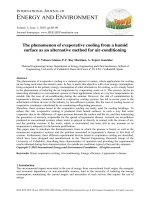
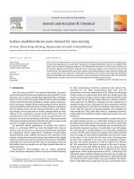
Fig. 1. (a) Optical micrograph of the device, integrated with the solution-exchanging chamber. (b–d) Scanning electron micrographs of the sample with six devices integrated
in a single chip, a single device and a single wire. The scale bars are 1 mm, 10 m and 2 m in (a), (b) and (c), respectively.
with the drain voltage V
ds
. However, the dependence of the sur-
face potential on the urea concentration is independent of V
ds
. This
provides a simple method of calibrating the response.
2. Experimental methods
2.1. Device fabrication
The urea biosensor with a set of silicon nanowires is fabricated
from silicon-on-insulator (SOI) wafer. The SOI wafer consists of
100 nm thick silicon as a device layer, 380 nm SiO
2
as an insula-
tion layer and a 500 m thick silicon substrate. The silicon device
layer is lightly doped with boron concentration 1–2 × 10
+15
cm
−3
.
The silicon wires are typically 4–8 m long, and the width can be
designed down to 50 nm in our experiments. The silicon nanowires
are first patterned with electron beam lithography. Then a ∼40 nm
layer of chromium is evaporated as a mask by thermal evaporator.
Further reactive ion etching (RIE) exposes the two side walls of sil-
icon wires. Source and drain contacts are also defined by electron
beam lithography and Ti/Au are deposited in a thermal evaporator,
without further high temperature annealing process or doping. A
typical chip in our experiments includes six devices. Fig. 1(b) shows
a scanning electron micrograph of the device with six devices in a
single chip. Fig. 1(c) is a single device with multiple wires. Multi-
ple wires design increases the measurement signal (conductance of
the device) while keeping the small surface-to-volume ratio, so the
signal noise ratio. Fig. 1(d) is a single wire with 100 nm width. The
silicon nanowires were further covered with 10 nmAl
2
O
3
, grown by
atomic layer deposition (ALD), to prevent current leakage between
analyte solution and silicon nanowires.
2.2. Surface modification
The silicon wire FET sensor is modified with urease follow-
ing procedure below. Before modification, the Al
2
O
3
surface was
treated with oxygen plasma [14] (50 mW power, 30 sccm flow rate
for 1 min) for two purposes. One is for cleaning the sample surface,
and the other one is for generating a hydrophilic surface. The wires
are first put into 3-aminopropyltriethoxy silane (APTES) solution
(3% in ethanol with 5% water) for 2 h. The device is rinsed with
ethanol solution for five times before baking at 110
◦
C for 10 min.
After wire bonding, 2% urease in 20 mM NaCl solution (5% glyc-
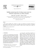
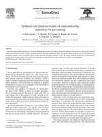
Fig. 2. Differential conductance measurement circuit.
Y. Chen et al. / Sensors and Actuators B 133 (2008) 593–598 595
erol, 5% Bovine Serum Albumin, BSA) is deposited on the sample
and is kept in glutaraldehyde vapour for 40 min. The sample is
then dried in air for 15 min. After modification, the sample is cov-
ered with solution-exchanging chamber and the devices are kept
in buffer solution before further calibration and measurements. All
urea samples used in our experiment contain 50 mM NaCl solu-
tion.
2.3. Solution-exchanging chamber
The solution-exchanging chamber is made of polycarbonate
(PC), with three holes (1.1 mm diameter), one serving as an inlet
channel, a second as a fluid output channel and the third for inser-
tion of a reference gate electrode. Fig. 1(a) shows a chip placed
under a solution-exchanging chamber. A thin parafilm spacer with
a hole in the centre is inserted between the chamber and the chip
to enable a small volume of solution to flow across on the device.
The typical volume of the solution used for the experiments is
20–30 l. This configuration offers superior time response when
compared to microfluidic chambers where laminar flow can dom-
inate.
2.4. Measurements setup
The measurement circuit includes a small ac modulation (pro-
vided by an EG&G 5210 lock-in amplifier), superimposed on the
dc bias across the nanowire (provided by a Keithley 2400 source
meter). The ac modulation and the dc bias are added by a non-
inverting summing circuit, integrated with the preamplifier circuit
(Fig. 2). The entire device is placed in an RF-shielde d aluminium
box to prevent noise pickup. Differential conductance measure-
ments are done by sweeping the dc bias at constant ac modulation
amplitude, and measuring the response with the lock-in amplifier,
referenced to the ac signal frequency. The quantity of interest is the
change in g, the differential conductance due either to a change in
the reference gate voltage V
rg
, or to a change in concentration C.
3. Results and discussion
Urea is also known as carbamide and it was the first organic
compound to be artificially synthesized from inorganic starting
materials [17]. The monitoring of urea concentration in blood is
a way to evaluate kidney disease [18].
When urea reaches the functionalized surface, the enzyme cat-
alyzes the following reaction [19]:
urea + 3H
2
O
Urease
−→ 2NH
4
+
+ HCO
3
−
+ OH
−
.
Although both NH
4
OH and H
2
CO
3
affect the hydrogen ion
concentration, and hence the pH, of the solution, the dissocia-
tion constant K
d
of NH
4
OH is 1.8 × 10
−5
M, while K
d
of CO
2
is
4.2 × 10
−7
M; the NH
4
OH is stronger than carbonic acid created by
CO
2
, resulting in an increase in the pH at the gate interface. Roughly
speaking, the enzyme FET sensor may be considered to function as
a pH sensor. The sensitivity of the device depends on the sensitivity
to the local pH change of the solution introduced by the catalytic
reaction. We first characterize the pH sensitivity of the device with
silicon wires without enzyme modification.Fig. 3(a) shows therela-
tionship between the differential conductancechange and pH value
of the solution. The inset is the real time measurement of the dif-
ferential conductance of the device, the wire width is 100 nm and
covered with 10 nm of Al
2
O
3
, the reference gate voltage is set to be
0V. When the pH value of the solution decreased, surface potential
« on the silicon wire increased [8]:
« =−2.3˛
kT
q
pH
bulk
q is the proton charge, k is Boltzmann’s constant, and T the abso-
lute temperature. ˛ is constant related to the buffer capacity of
the surface and it is between 0 and 1. The physical quantity we
are measuring in our experiments is device conductance. In order
to calibrate the pH change to conductance change of the device,
we change the reference gate voltage while keeping the solution
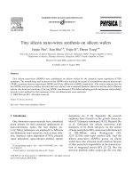
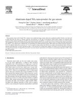
Fig. 3. Sensor sensitivity calibration with pH measurements. (a) Differential conductance change versus pH value of the solution (inset is real time differential conductance
measurement when pH value of the solution changed sequentially). (b) Differential conductance versus reference gate voltage V
rg
(inset is real time differential conductance
measurement when reference gate voltage changed sequentially). (c) Calibrated surface potential change introduced by the pH change of the solution.
596 Y. Chen et al. / Sensors and Actuators B 133 (2008) 593–598
character the same. For our device, as can be seen in Fig. 3(b), con-
ductance is not in a linear relation with gate voltage. This is because
the existence of the Schottky barrier of the two electrical contacts.
By operating the device at small negative source drain voltage, the
device can be used as ion sensitive sensor. By converting the con-
ductance change introduce d by urea to the reference gate voltage
change which is proportional to the surface potential change in
Fig. 3(c), we find the sensitivity is around 57 mV/pH, which is close
to the limit of most FET sensors [8]. This calibration confirmed that
nanoscale FET sensor has comparable if not better sensitivity to
pH comparing with large-scale FET sensor and shows very high
stability at the same time.
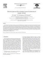
Fig. 4. (a) Differential conductance versus urea concentration, V
ds
= −0.6 V
andV
rg
= 0 V. Inset is real time differential conductance measurement of the device
when the urea concentration is changed; all solutions contents 50 mM of NaCl. (b)
Differential conductance versus reference gate voltage in same solution. Inset is the
real time differential conductance measurement. (c) Surface potential change versus
urea concentration. Data is normalized from (a) and (b).
Fig. 5. Stability of the device. (a) Differential conductance versus urea concentra-
tion; data are taken during 6 days after device is fabricated. (b) Surface potential
change versus urea concentration; data is normalized by reference gate voltage
change.
Fig. 4 gives the real time response of the device surface modi-
fied by urease enzyme when adding urea solutions with different
concentrations. After each solution change the data taking is
paused for 10 min to wait for transient signals to decay and the
response to stabilize. The time response is limited not by the dif-
fusion time scale over the small sample chamber but rather by
the presence of multiple layers of enzyme molecules on the sur-
face. Further improvement of the response time can be done by
modifying the surface with monolayer enzyme [4]. After urea mea-
surement, the reference gate voltage is changed to get a relationship
between the gate voltage and conductance similar to what we
did in pH measurements. By comparing the data during urea con-
centration change and during the reference gate voltage change,
we can normalize the urea concentration to reference gate volt-
age (surface potential) change [20]. Fig. 4(c) shows a monotonic
dependence of the surface potential on the urea concentration,
with a linear dependence in the urea concentration range from
0.1–0.68 mM. When increasing the urea concentration, the results
saturates because of the activity change of the urease enzyme.
From our data, our devices are useful in a high sensitive sensing
application.
In order to satisfy clinic applications, such as long time monitor-
ing of the target concentration and reusable sensor, it is important
to have highly stable sensor. Further experiments are done to study
the stability of our sensor by measuring the conductance change
due to the presence of urea. Fig. 5(a) shows the conductance change
at first day, third day and sixth day. Like many silicon devices, due to
drifting problem of the silicon device we noticed that the conduc-
tance change can be up to 25% (compare the conductance change
Y. Chen et al. / Sensors and Actuators B 133 (2008) 593–598 597
Fig. 6. (a) Differential conductance versus urea concentration when data are taken
at different source drain voltage: V
ds
= −0.6 V and V
ds
= −0.7 V. (b) Surface potential
change at differential source drain voltage. Data is normalized by reference gate
voltage change.
introduced by 0.68 mM urea of first day and third day). But if we
normalize the data with surface potential change by doing refer-
ence gate measurement like in Fig. 5(b), we found that the drifting
potential is less than 10%, which offers possibility of high repeatable
and reusable urea sensors.
The surface potential change introduced by the urea concen-
tration is only related to the solution character and should not
depend on the sensor device or on the measurement conditions. In
order to confirm this we did the same measurements by change the
source drain bias voltage. Fig. 6 shows the data taken at V
ds
= −0.6 V
and V
ds
= −0.7 V. As described in a previous paper [20], our device
response gives bigger signal when V
ds
is set at higher negative
value; this is consistent with the data in Fig. 6(a). But if we nor-
malize the conductance change to the surface potential change of
the device like in Fig. 4, the data in Fig. 1(b) shows that the surface
potential change due to the catalytic reaction is not affected by the
source drain voltage.
4. Conclusion
Silicon nano-channel FET sensor is fabricated from a top down
lithography approach. The device shows a good sensitivity to the
pH change of the solution. This confirmed that the surface poten-
tial change of the nanoscale device introduced by the pH value of
the solution is comparable to if not better than large-scale devices.
The surface of the silicon-channels is further modified with urease
enzyme and used for the detection of the concentration of the urea.
The device response is in a linear relationship with the urea concen-
tration of the solution in the range of 0.1–0.68 mM. Our nanoscale
device shows very good stability and offers the possibility of highly
efficient, repeatable enzyme sensor array.
Acknowledgements
The authors acknowledge support from the Department of
Defense and the National Science Foundation and this work is per-
formed in part at the Photonics Center.
References
[1] P. Bergveld, Development of an ion-sensitive solid-state device for neurophys-
iological measurements, IEEE Trans. Biomed. Eng. BME 17 (1970) 70–71.
[2] W.Y. Chung, C.H. Yang, D.G. Pijanowska, P.B. Grabiec, W. Torbicz, ISFET perfor-
mance enhancement by using the improved circuit techniques, Sens. Actuators
B: Chem. 113 (2006) 555–562.
[3] P.A. Hammond, D.R.S. Vumming, Performance and system-on-chip integra-
tion of an unmodified CMOS ISFET, Sens. Actuators B: Chem. 111–112 (2005)
254–258.
[4] A.B. Kharitonov, M. Zayats, A. Lichtenstein, E. Katz, I. Willner, Enzyme
monolayer-functionalized field-ef fect transistors for biosensor applications,
Sens. Actuators B: Chem. 70 (2000) 222–231.
[5] M. Kamahori, Y. Ishige, M. Shimoda, A novel enzyme immunoassay based on
potentiometric measurement of molecular adsorption events by an extended-
gate field-effect transistor sensor, Biosens. Bioelectron. 22 (2007) 3080–3085.
[6] J. Liu, G. Li, Application of biosensors for diagnostic analysis and bioprocess
monitoring, Sens. Actuators B: Chem. 65 (2000) 26–31.
[7] A. Kim, C.S. Ah, H.Y. Yu, J H. Yang, I B. Baek, C. Ahn, C.W. Park, M.S Jun, Ultra-
sensitive, label-free, and real-time immunodetection using silicon field-effect
transistors, Appl. Phys. Lett. 91 (2007) 103901.
[8] P. Bergveld, Thirty years of ISFETOLOGY what happened in the past 30 years
and what may happen in the next 30 years, Sens. Actuators B: Chem. 88 (2003)
1–20.
[9] E. Katz, I. Willner, Probing biomolecular interactions at conductive and semi-
conductive surfaces by impedance spectroscopy: routes to impedimetric
immunosensors, DNA-sensors, and enzyme, Biosens. Electroanal. 15 (2003)
913–945.
[10] E. Eteshola, D. Leckband, Development and characterization of an ELISA assay
in PDMS microfluidic channels, Sens. Actuators B: Chem. 72 (2001) 129–133.
[11] R.M. Ma, L. Dai, G.G. Qin, Enhancement-mode metal-semiconductor field-
effect transistors based on single n-CdS nanowires, Appl. Phys. Lett. 90 (2007)
093109.
[12] S.J. Tans, A.R.M. Verschueren, C. Dekker, Room-temperature transistor based on
a single carbon nanotube, Nature 393 (1998) 49–52.
[13] Z. Li, Y. Chen, X. Li, T.I. Kamins, K. Nauka, R.S. Williams, Sequence-specific label-
free DNA sensors based on silicon nanowires, Nano Lett. 4 (2004) 245–247.
[14] Y. Cui, Q. Wei, H. Park, C.M. Lieber, Nanowire nanosensors for highly sensitive
and selective detection of biological and chemical species, Science 293 (2001)
1289–1292.
[15] Y. Chen, X. Wang, S. Erramilli, P. Mohanty, A. Kalinowski, Silicon-based nano-
electronic field-effect pH sensor with local gate control, Appl. Phys. Lett. 89
(2006) 223512.
[16] E. Stern, J.F. Klemic, D.A. Routenberg, P.N. Wyrembak, D.B. Turner-Evans, A.D.
Hamilton, D.A. LaVan, T.M. Fahmy1, M.A. Reed., Label-free immunodetec-
tion with CMOS-compatible semiconducting nanowires, Nature 445 (2007)
519–522.
[17] T.P. Mommsen, P.J. Walsh, Evolution of urea synthesis in vertebrates: the Piscine
connection, Science 243 (1989) 72–75.
[18] F. Kuralay, H. Ozyoruk, A. Yildiz, Potentiometric enzyme electrode for urea
determination using immobilized urease in poly(vinylferrocenium) film, Sens.
Actuators B: Chem. 109 (2005) 194–199.
[19] B. Premanode, C. Toumazou, A novel, low power biosensor for real time mon-
itoring of creatinine and urea in peritoneal dialysis, Sens. Actuators B: Chem.
120 (2007) 732–735.
[20] Y. Chen, X. Wang, M.K. Hong, S. Erramilli, P. Mohanty, C. Rosenberg, Nanoscale
field effect transistor for biomolecular signal amplification, Appl. Phys. Lett. 91
(2007) 243511.
Biographies
Yu Chen obtained his bachelor and master degree in physics in 1999 and 2002 from
the Fudan University of Shanghai, China. His thesis for master’s degree is about
deep level defects of silicon and silicide. He is currently a PhD. candidate of Boston
University and is doing his PhD thesis on silicon nanowire sensors.
Xihua Wang received his degree in physics in 2003 from Peking University. He
is a PhD student in physics department at Boston University. His current research
interest is in the field of nano-electronic and nano-optic biosensing.
598 Y. Chen et al. / Sensors and Actuators B 133 (2008) 593–598
Mi Hong graduated in Physics from Seoul National University, and got her PhD in
Biophysics from the University of Illinois. She did post-doctoral research in Physics
at Princeton University, before becoming a Research Professor in Physics at Boston
University. She is currently a Visiting Professor at the Department of Applied Mathe-
matics and Theoretical Physics, and her research interests are inthefieldofBiological
Physics.
Shyamsunder Erramilli got his PhD degree in Physics from the University of Illinois,
after graduating from the Indian Institute of Technology Mumbai. He was a faculty
member in the Physics department at Princeton University, where was awarded a
duPont Young Professor award. He is currently a Professor in Physics and Biomedical
Engineering at Boston University, and is at the Photonics Center at Boston.
Dr. Pritiraj Mohanty is a Professor of Physics at Boston University. Prior to join-
ing Boston University, he was a Postdoctoral Research Faculty at California Institute
of Technology. He received his PhD from the University of Maryland in nano-
electronics, and his thesis work focused on the concept of direction of time
at the quantum-classical border. He is the recipient of the NSF Career Award
and Sloan Fellowship. His current research focuses on nanomechanical systems
and their use as memory cells, and passive devices and frequency-selecting ele-
ments in wireless communication systems. Other areas of research interests
include development of nanoscale biosensors for cancer detection, and quantum
computing.