- Trang chủ >>
- Khoa Học Tự Nhiên >>
- Vật lý
single crystalline a - fe2o3 with hierarchicalstructurescontrollable
Bạn đang xem bản rút gọn của tài liệu. Xem và tải ngay bản đầy đủ của tài liệu tại đây (1.31 MB, 8 trang )
Single-crystalline a-Fe
2
O
3
with hierarchical structures: Controllable
synthesis, formation mechanism and photocatalytic properties
Jianmin Gu, Siheng Li, Enbo Wang
Ã
, Qiuyu Li, Guoying Sun, Rui Xu, Hong Zhang
Key Laboratory of Polyoxometalate Science of Ministry of Education, Department of Chemistry, Northeast Normal University, Changchun, Jilin 130024, People’s Republic of China
article info
Article history:
Received 21 November 2008
Received in revised form
16 January 2009
Accepted 26 January 2009
Available online 12 February 2009
Keywords:
Hematite
Hierarchical structures
Photocatalytic properties
abstract
A dual iron precursors system in a hydrothermal process was developed for controllable fabrication of
a-Fe
2
O
3
hierarchical structures with different morphologies. Micro-pines, snowflakes and bundles were
successfully synthesized simply by tuning the total concentration of the two iron precursors K
4
[Fe(CN)
6
]
and K
3
[Fe(CN)
6
] and their molar ratio. The obtained a-Fe
2
O
3
hierarchical structures were characterized
using field-emission scanning electron microscopy, transmission electron microscopy, X-ray powder
diffraction, X-ray photoelectron spectroscopy and energy-dispersive X-ray analysis. The effect of
experimental conditions on the morphologies of the
a-Fe
2
O
3
crystals was systematically investigated.
A possible formation mechanism of different
a-Fe
2
O
3
hierarchical structures was proposed. Good
photocatalytic properties were observed for all the hierarchical structures.
& 2009 Published by Elsevier Inc.
1. Introduction
Nanomaterials with a hierarchical structure have attracted
intensive research attention. Their complicated structures are
usually concomitant with diverse characteristics, thus having
various applications. With the high surface area specific for
nanomaterials [1], these hierarchical structures often grow into
micrometer-scaled materials, bearing the mechanical robustness
desired in various fields. Recently, nanomaterials with various
hierarchical morphologies [2–7] have been synthesized and
successfully used in catalysis and environmental improvement,
and as sensors in biological systems. Template methods [8],
thermal evaporation [9], electrochemical deposition [10], chemi-
cal vapor deposition [11] and hydrothermal synthesis [12] are the
common methods to prepare this kind of materials. Among these
methods, hydrothermal process bears the advantage that it can
initiate the nucleation in the growth of micro- and nano-crystals,
and promote the formation of crystalline products to completion
under non-equilibrium conditions [13]. This method has been
widely used in preparing various hierarchical structures [14].
Hematite (
a
-Fe
2
O
3
) is the most stable iron oxide with n-type
semiconducting properties (band gap E
g
¼ 2.1eV) at ambient
conditions [15]. Its potential applications have been explored in
fields including photocatalysis [16], gas sensors [17], lithium ion
battery [18] and magnetic materials production [19].
a
-Fe
2
O
3
nano-crystals with various morphologies such as urchinlike [20],
quasicubic [21], belts [22], tubes [23,24], nanorings [25], rods [26],
hollow spheres [27] and nanorhombohedra [28] have been
fabricated, and their various functions have been tested. Control-
ling the morphology in the synthesis of
a
-Fe
2
O
3
hierarchical
structures has thus become the major synthetic goal. Lately, Cao
et al. [29] described a facile route for the preparation of
a
-Fe
2
O
3
micro-pine microcrystals. Hu et al. [30] obtained
a
-Fe
2
O
3
snowflake hierarchical structures on a large scale in an efficient
microwave-assisted hydrothermal process. Gong’s group [31] has
synthesized
a
-Fe
2
O
3
crystals with different morphologies by
changing the pH value in an aqueous reaction system. In all these
processes, [Fe(CN)
6
]
3À
ions were used as a single iron source for
the slow generation of Fe
3+
ions under a hydrothermal condition.
However, it is still not easy to control the morphology and
photocatalytic properties of the
a
-Fe
2
O
3
crystals systematically
using only one iron precursor. Developing a simple and more
accurate method to synthesize
a
-Fe
2
O
3
crystals with various
morphologies is still in need.
Herein, a dual iron precursors system was developed for the
controllable synthesis of
a
-Fe
2
O
3
hierarchical structures. Metal
complexes, [Fe(CN)
6
]
4À
and [Fe(CN)
6
]
3À
in this work, usually can
provide a proper environment for the generation of novel structures
based on their flexible coordination modes in the synthetic progress
[29–3 1].
a
-Fe
2
O
3
hierarchical structures with different morpholo-
gies (micro-pine, snowflake and bundles) were successfully fabri-
cated simply by tuning the total concentration of the two iron
precursors and their molar ratio in a hydro thermal process.
A possible formation mechanism of different
a
-Fe
2
O
3
hierarch ical
structures was also proposed. Meanwhile, the photocatalytic
ARTICLE IN PRESS
Contents lists available at ScienceDirect
journal homepage: www.elsevier.com/locate/jssc
Journal of Solid State Chemistry
0022-4596/$ - see front matter & 2009 Published by Elsevier Inc.
doi:10.1016/j.jssc.2009.01.041
Ã
Corresponding author. Fax: +86 43185098787.
E-mail addresses: ,
(E. Wang).
Journal of Solid State Chemistry 182 (2009) 1265–1272
property of the
a
-Fe
2
O
3
hierarchical structures was investigated in
the ph o tocatal ytic degradation of salicylic acid.
2. Experimental section
2.1. Materials
All chemicals, K
3
[Fe(CN)
6
], K
4
[Fe(CN)
6
] Á 3H
2
O and salicylic acid are
of analytical grade and used as received without further purification.
2.2. Synthesis
A typical synthesis procedure of the
a
-Fe
2
O
3
snowflake
hierarchical structure was as follows: 0.6 mmol K
4
[Fe(CN)
6
] Á 3H
2
O
and 0.12 mmol K
3
[Fe(CN)
6
] (the molar ratio of K
4
[Fe(CN)
6
]/
K
3
[Fe(CN)
6
] was 5) were dissolved in 12 mL distilled water under
magnetic stirring for 40 min at room temperature until a yellow
transparent solution appeared. Then, the yellow solution was
transferred into a 15 mL Teflon-lined autoclave and sealed. After
hydrothermally treated at 140 1C for 48 h, the autoclave was
cooled to room temperature naturally. Finally, the final products
were separated by centrifugation, washed with distilled water and
absolute ethanol repeatedly before oven drying at 60 1C for 24 h.
The synthesis procedures of
a
-Fe
2
O
3
micro-pine and bundles
hierarchical structures were similar as that of the snowflake
hierarchical structure except that the total concentration of the
two iron precursors and their molar ratio were changed. These
reactions were easily repeated, and the resulted structures were
highly stable. No morphology or composition change was observed
over several months when stored in air or absolute ethanol.
2.3. Characterization
Transmission electron microscopy (TEM, Hitachi-7500, operat-
ing voltage of 120 kV) and field-emission scanning electron
microscopy (FESEM, XL30, Philips, operating voltage of 20kV)
were used to observe the morphologies of the final products.
X-ray diffraction patterns (XRD) were measured using a Rigaku
D/max-IIB X-ray diffractometer at a scanning rate of 41/min with
2
y
ranging from 101 to 901, using CuK
a
radiation (
l
¼ 1.5418 A
˚
).
The chemical compositions were studied using X-ray photoelec-
tron spectroscopy (XPS) and energy-dispersive X-ray analysis
(EDX). A Hitachi F-4500 fluorophotometer was used in the study
of the photocatalytic property of
a
-Fe
2
O
3
structures.
2.4. Photocatalysis experiments
In a typical process, 20 mg of
a
-Fe
2
O
3
hierarchical structures
and 5 mg of salicylic acid were dissolved in 50 mL distilled water
and then magnetically stirred in the dark for 50 min to generate a
good dispersion and to establish the adsorption–desorption
equilibrium between the organic molecules and the catalyst
surface. The solution was then exposed to UV irradiation from a
125 W Hg lamp at a distance of 3–4 cm between the liquid surface
and the lamp. The solution was stirred with a magnetic stir bar
during irradiation. In total, 2 mL of samples were taken out from
the beaker at different time intervals. After
a
-Fe
2
O
3
was removed
using centrifugation and filtration, the solution was used for
fluorescence analysis. The emission intensity of salicylic acid at
412 nm was monitored with the excitation wavelength at 296 nm.
3. Results and discussion
3.1. Characterizations of
a
-Fe
2
O
3
micro-pine hierarchical structure
Fig. 1 shows the FESEM images with different magnifications of
the
a
-Fe
2
O
3
micro-pine hierarchical structures synthesized when
the concentration of K
4
[Fe(CN)
6
] was 0.01 M and the molar ratio of
K
4
[Fe(CN)
6
]/K
3
[Fe(CN)
6
] was 1/5. The low-magnification image in
Fig. 1a shows that the products have regular micro-pine
structures. Fig. 1b reveals the difference between the two surfaces
of one micro-pine structure. Micro-pine hierarchical structures
ARTICLE IN PRESS
Fig. 1. FESEM images of micro-pine hierarchical structures prepared when the concentration of K
4
[Fe(CN)
6
] was 0.01 M and the molar ratio of K
4
[Fe(CN)
6
]/K
3
[Fe(CN)
6
] was
1/5: (a) panorama of micro-pine; (b) micro-pine in two opposite directions; high-magnification FESEM image of a single micro-pine in one direction (c) and (d) in the
opposite direction.
J. Gu et al. / Journal of Solid State Chemistry 182 (2009) 1265–12721266
with a clear central trunk and highly ordered parallel branches
distributed on both sides of the trunk are obviously observed. The
length of the central trunks is about 4.5
m
m, and that of the branch
trunk ranges from 100 nm to 1.5
m
m. The high-magnification
images in Fig. 1c and d show the details of the trunk and branches.
The central trunk is composed of orderly arranged trigonal
particles with sizes being about 200 nm (Fig. 1c). All the branch
trunks consist of regular nanoparticles with sizes of about 100 nm
(Fig. 1d). Parallel nanorods (100–200 nm) can be defined as the
subunits of the branches.
A typical TEM image of
a
-Fe
2
O
3
micro-pines is shown in
Fig. 2a. The length of the central trunks is about 4.5
m
m, in
agreement with the observation from FESEM images (Fig. 1b).
Fig. 2b and the inset show the morphology of a broken
a
-Fe
2
O
3
micro-pine hierarchical structure. The SAED pattern of the
products demonstrates that the
a
-Fe
2
O
3
micro-pine structures
are single crystalline (Fig. 2c).
The composition and phase purity of the samples were
examined using XRD. Fig. 3 shows the typical XRD pattern of
the micro-pine hierarchical structure. According to the reflection
peak positions and relative intensities, the pattern is in good
agreement with the literature values and can be indexed to the
hexagonal phase of
a
-Fe
2
O
3
(hematite) (a ¼ 5.035 A
˚
, c ¼ 13.740A
˚
,
JCPDS no. 33-0664) with no other peaks of impurities detected.
3.2. Characterizations of
a
-Fe
2
O
3
snowflake hierarchical structure
Sixfold-symmetric
a
-Fe
2
O
3
snowflake hierarchical structures
were obtained when the concentration of K
4
[Fe(CN)
6
] was 0.05 M
and the molar ratio of K
4
[Fe(CN)
6
]/K
3
[Fe(CN)
6
] was 5/1, as seen
from the low-magnification FESEM image (Fig. 4a). The individual
a
-Fe
2
O
3
snowflake hierarchical structure as shown in Fig. 4b
consists of self-assembled sixfold-symmetric dendritic branch
with the average length of each trunk being about 4.5
m
m. The
intersect angle of the adjacent branches is 601. Fig. 4c shows
orderly arranged nanorods with the length of about 200–700 nm
grow on the both sides of a trunk and are parallel to each other.
Energy-dispersive X-ray analysis shown in Fig. 4d proves the
presence of Fe and O in the
a
-Fe
2
O
3
snowflake hierarchical
structure. The peaks corresponding to the Si atom and Au atom,
respectively, come from the silicon substrate and sprayed gold.
The morphology of the
a
-Fe
2
O
3
snowflakes was also investi-
gated by TEM (Fig. 5). Fig. 5a shows a typical TEM image of an
individual symmetric
a
-Fe
2
O
3
snowflake hierarchical structure,
giving a further insight into the morphology (Fig. 4b). The TEM
image of an asymmetric
a
-Fe
2
O
3
snowflake hierarchical structure
is also given in Fig. 5b. The SAED pattern (Fig. 5c) suggests that the
a
-Fe
2
O
3
snowflake hierarchical structure is single crystalline.
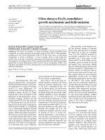
Fig. 6 shows the typical XRD pattern of the snowflake
hierarchical structures. According to the reflection peak positions
and relative intensities, the pattern is in good agreement with the
literature values and can be easily indexed to the hexagonal phase
of
a
-Fe
2
O
3
(hematite) (a ¼ 5.035 A
˚
, c ¼ 13.740 A
˚
, JCPDS no. 33-
0664) with no other peaks of impurities detected. Furthermore,
the surface electronic states and the chemical composition of the
product are examined using XPS. In the high-resolution Fe 2p
spectrum (Fig. 7), two peaks at binding energies of about 711 eV
for Fe 2p
3/2
and about 724 eV for Fe 2p
1/2
with a shakeup satellite
at about 719 eV prove the presence of Fe (
b
)in
a
-Fe
2
O
3
[32].
3.3. Characterizations of
a
-Fe
2
O
3
bundles hierarchical structure
Fig. 8 showstheFESEMimagesof
a
-Fe
2
O
3
bundles hierarchical
structures obtained when the concentration of K
4
[Fe(CN)
6
]is0.1M
and the molar ratio of K
4
[Fe(CN)
6
]/K
3
[Fe(CN)
6
]is1/8.Thelow-
magnification FESEM image of the
a
-Fe
2
O
3
bundles is shown in
Fig. 8a. The high -magnification FESE M imag e (Fig. 8b) shows an
individual
a
-Fe
2
O
3
bundles structur e, which is composed of par allel
nanorods with diameters of about 1 60 nm and average lengths of
several micrometers. TEM imag es are shown in Fig. 9a. The SAED
pattern (Fig. 9b) indicates the single-cry stalline nature of the samples.
Fig. 10 shows the typical XRD pattern of the samples. According
to the reflection peak positions and relative intensities, the
pattern is in good agreement with the literature values and can
be easily indexed to the hexagonal phase of
a
-Fe
2
O
3
(hematite)
(a ¼ 5.035 A
˚
, c ¼ 13.740 A
˚
, JCPDS no. 33-0664) with no other
peaks of impurities detected.
3.4. The effect of experimental conditions on the morphologies of the
a
-Fe
2
O
3
crystals
To study the effect of experimental conditions on the morpho-
logies of the
a
-Fe
2
O
3
crystals, series of control experiments were
ARTICLE IN PRESS
Fig. 2. (a) TEM image of a single micro-pine; (b) SEM image and TEM (inset) of a broken micro-pine and (c) SAED pattern of micro-pine.
Fig. 3. XRD pattern of the sample prepared when the concentration of K
4
[Fe(CN)
6
]
was 0.01M and the molar ratio of K
4
[Fe(CN)
6
]/K
3
[Fe(CN)
6
] was 1/5 at 140 1C for
48 h.
J. Gu et al. / Journal of Solid State Chemistry 182 (2009) 1265–1272 1267
ARTICLE IN PRESS
Fig. 4. FESEM images of snowflake hierarchical structures prepared when the concentration of K
4
[Fe(CN)
6
] was 0.05 M and the molar ratio of K
4
[Fe(CN)
6
]/K
3
[Fe(CN)
6
] was
5/1: (a) panorama of snowflake; (b) single snowflake; (c) high-magnification FESEM image of the one petal of a snowflake and (d) EDS pattern of snowflake.
Fig. 5. (a) TEM image of a single snowflake; (b) asymmetric shape of a snowflake and (c) SAED pattern of snowflake.
Fig. 6. XRD pattern of the sample prepared when the concentration of K
4
[Fe(CN)
6
]
was 0.05 M and the molar ratio of K
4
[Fe(CN)
6
]/K
3
[Fe(CN)
6
] was 5/1 at 140 1C for
48 h.
Fig. 7. XPS spectrum of Fe 2p of
a
-Fe
2
O
3
snowflake.
J. Gu et al. / Journal of Solid State Chemistry 182 (2009) 1265–12721268
carried out with the total concentration of the two iron precursors
ranging from 0.01 to 1.0 M and their molar ratio increased in a
systematic way. When the total concentration of the two iron
precursors was kept at 0.08 M and their molar ratio was changed,
micro-pine hierarchical structures precipitated out when the
molar ratio of K
4
[Fe(CN)
6
]/K
3
[Fe(CN)
6
] was 1/7 (Fig. 11a) or 2/6;
micro-pine hierarchical structures with some
a
-Fe
2
O
3
snowflake
hierarchical structures came out at the same time when the molar
ratio of K
4
[Fe(CN)
6
]/K
3
[Fe(CN)
6
] was 3/5, 4/4 or 5/3; when the
molar ratio of K
4
[Fe(CN)
6
]/K
3
[Fe(CN)
6
] was 6/2 (Fig. 11b) or 7/1,
snowflake hierarchical structures were predominant in the
products. When the total concentration of the two iron precursors
was kept at 0.8 M and the molar ratio was varied, bundles instead
of micro-pines or snowflakes were obtained when the molar ratio
of K
4
[Fe(CN)
6
]/K
3
[Fe(CN)
6
] was 1/7 (Fig. 11c), 2/6, 3/5 and 4/4;
when the molar ratio of K
4
[Fe(CN)
6
]/K
3
[Fe(CN)
6
] was changed to
5/3 (Fig. 11d), 6/2 or 7/1, the product appeared to be unformed
snowflakes.
Based o n t hese observations, when the t o tal c oncentr ation of the
two iron p recursors and their molar r atio wer e changed, the
morphology of
a
-Fe
2
O
3
crystal can be tuned to micro-pine, snowflake,
bundles and unformed snowflakes. Thus, we believe that the tot al
concentration of the two ir on precursors and their molar ratio pl ay a
crucial role o n c ontrolling the mor phology of
a
-Fe
2
O
3
crystal.
3.5. Formation mechanisms of different
a
-Fe
2
O
3
hierarchical
structures
3.5.1.
a
-Fe
2
O
3
micro-pine and snowflake hierarchical structures
[Fe(CN)
6
]
3À
and [Fe(CN)
6
]
4À
, with the standard equilibrium
constant are 1.0 Â 10
42
and 1.0 Â 10
35
, respectively, are both stable
ARTICLE IN PRESS
Fig. 8. FESEM images of bundles hierarchical structures prepared when the concentration of K
4
[Fe(CN)
6
] was 0.1M and the molar ratio of K
4
[Fe(CN)
6
]/K
3
[Fe(CN)
6
] was 1/8:
(a) panorama of bundles and (b) single bundles.
Fig. 9. (a) TEM image of single bundles and (b) SAED pattern of bundles.
Fig. 10. XRD pattern of the sample prepared when the concentration of
K
4
[Fe(CN)
6
] was 0.1 M and the molar ratio of K
4
[Fe(CN)
6
]/K
3
[Fe(CN)
6
] was 1/8 at
140 1C for 48 h.
J. Gu et al. / Journal of Solid State Chemistry 182 (2009) 1265–1272 1269
in the aqueous solution and almost no free Fe
3+
ions can be
detected at room temperature. Obviously, [Fe(CN)
6
]
4À
exhibits
lower stability than [Fe(CN)
6
]
3À
in the aqueous solution. Con-
sidering different stability, if the two iron precursors (K
3
[Fe(CN)
6
]
and K
4
[Fe(CN)
6
]) are employed to the same reaction system,
whether any novel
a
-Fe
2
O
3
structure could be obtained.
A three-step formation mechanism of the different structures
was proposed in Scheme 1. First, the Fe
3+
ions were generated
from slowly dissociation from [Fe(CN)
6
]
3À
as well as from the
oxidation of Fe
2+
ions dissociated slowly from [Fe(CN)
6
]
4À
by the
dissolved oxygen. Then all the Fe
3+
ions were hydrolyzed
in aqueous solutions and FeOOH or Fe(OH)
3
were generated.
FeOOH or Fe(OH)
3
was finally decomposed to form
a
-Fe
2
O
3
crystals.
Based on the results from the control experiments, the
employment of a small amount of K
4
[Fe(CN)
6
] cannot be enough
to affect the generation rate of the Fe
3+
ions in the entire system.
Only
a
-Fe
2
O
3
micro-pine hierarchical structures could be ob-
tained when both the concentration of K
4
[Fe(CN)
6
] and their
molar ratio were low (Fig. 11a). A mature formation mechanism of
a
-Fe
2
O
3
micro-pine hierarchical structures obtained via a single
iron precursor K
3
[Fe(CN)
6
] has been proposed in a previous
research [29]. Herein, a possible formation process of
a
-Fe
2
O
3
micro-pine hierarchical structures is demonstrated in Fig. 12. The
crystal structure (Fig. 12e) shows that /101
¯
0S are six equivalent
directions. However, due to spatial confinement, one of the
directions, such as [11
¯
00], could initiate fast growth. It is possible
to form a needle if the growth along [11
¯
00] is much faster than
along the other directions (Fig. 12a). Subsequent growth along the
other two crystallographically equivalent directions ([101
¯
0] and
[011
¯
0]) may result in the formation of symmetric branches on
both sides (Fig. 12b). With further growth, each side branch can
also grow along 7[011
¯
0] and 7[101
¯
0] to minibranches (Fig. 12c)
and finally
a
-Fe
2
O
3
micro-pine hierarchical structures are
obtained (Fig. 2a).
When the amounts of K
4
[Fe(CN)
6
] in the reaction systems were
relatively increased, the morphology of
a
-Fe
2
O
3
nano-crystals
changed from micro-pine (Fig. 11a) to snowflake (Fig. 11b).
A possible reason for the morphology change was that the
generation rate of Fe
3+
ions as well as the generation rate of
FeOOH/Fe(OH)
3
would increase dramatically. Thus, the tendency
of growth along the six crystallographically equivalent directions
/101
¯
0S would increase due to the increase of the kinetic factor
and the breaking of the limit on the spatial confinement of the
crystal growth. The growth of
a
-Fe
2
O
3
snowflake hierarchical
structures along [101
¯
0] and [011
¯
0] directions could also increase
[31]. As growth continues, all of the branches became thicker and
finally interconnected to form a compact snowflake (Fig. 12d).
Based on the above-mentioned ratiocination, the increase of
K
4
[Fe(CN)
6
] played a crucial role in the formation process of
a
-Fe
2
O
3
snowflake hierarchical structures.
Generally, as previous literature reported [33], hierarchical
structures are formed through a self-assembly process under non-
equilibrium conditions. Small bumps on the surface of a growing
crystal develop into large branches, and bumps on the branches
become side branches. Once branching instability applies itself to
a growing crystal, the dendrite structures are formed. This
instability plays a vital role in obtaining the complex structures
of the
a
-Fe
2
O
3
crystals. In solution growth system, once the initial
a
-Fe
2
O
3
crystals are formed, further coarsening needs further
diffusion of the
a
-Fe
2
O
3
crystals, which can slow the crystal
growth rate and then the morphology could be controlled. When
the diffusion of the bumps reaches the initial nucleated crystals
faster, bulk growth tends to be easier. For instance, in our
experiments obtaining snowflakes, large amounts of [Fe(CN)
6
]
4À
are employed, the generation rate of Fe
3+
ions increases and the
diffusion rate of subsequent formed
a
-Fe
2
O
3
will also increase.
The probability to attach simultaneously onto the six equivalent
facets of the initial crystals leads to the
a
-Fe
2
O
3
snowflake
hierarchical structures.
3.5.2.
a
-Fe
2
O
3
bundles hierarchical structures
In principle, the growth process of crystals consists of an initial
nucleating step and a subsequent growth step.
a
-Fe
2
O
3
is a polar
crystal, and the Fe
3+
and O
2À
ions are arranged alternatively
parallel to the (0001) plane [29]. The concentration is also a
critical factor for the crystalline phase of the nuclei and the
growth rate of the different crystal surfaces [34]. Thus, when
the total concentration of the two iron precursors is rather high,
the nucleation would be so rapid that more
a
-Fe
2
O
3
nuclei form
in the chemical systems. With the preferential growth along the
(0001) direction proceeding,
a
-Fe
2
O
3
nanorods would appear in
the products. Subsequently, these nanorods aggregate and grow
into bundles due to excess saturation. The formation of
a
-Fe
2
O
3
bundles involves spontaneous assembly and coalescence of
ARTICLE IN PRESS
Fig. 11. (a) Single micro-pine prepared when the concentration of K
4
[Fe(CN)
6
] was 0.01 M and the molar ratio of K
4
[Fe(CN)
6
]/K
3
[Fe(CN)
6
] was 1/7; (b) single snowflake
prepared when the concentration of K
4
[Fe(CN)
6
] was 0.06 M and the molar ratio of K
4
[Fe(CN)
6
]/K
3
[Fe(CN)
6
] was 6/2; (c) single bundles prepared when the concentration of
K
4
[Fe(CN)
6
] was 0.1M and the molar ratio of K
4
[Fe(CN)
6
]/K
3
[Fe(CN)
6
] was 1/7; and (d) panorama of unformed snowflake prepared when the concentration of K
4
[Fe(CN)
6
]
was 0.5 M and the molar ratio of K
4
[Fe(CN)
6
]/K
3
[Fe(CN)
6
] was 5/3.
Scheme 1. Schematic process for synthesis of the
a
-Fe
2
O
3
hierarchical structures.
J. Gu et al. / Journal of Solid State Chemistry 182 (2009) 1265–12721270
adjacent nanorods so that the surface energy could be reduced.
We must acknowledge that the exact mechanism for the
formation of
a
-Fe
2
O
3
bundles hierarchical structures is still
unclear. However, it is obvious that higher concentrations of the
two iron precursors are of great importance in the growth of
a
-Fe
2
O
3
bundles hierarchical structures.
ARTICLE IN PRESS
Fig. 12. Proposed growth processes of
a
-Fe
2
O
3
micro-pine and snowflake.
Fig. 13. Change in fluorescence intensity of salicylic acid (100 mgL
À1
): (a) direct photocatalysis; (b) in the presence of 20 mg
a
-Fe
2
O
3
snowflake; (c) in the presence of
20 mg
a
-Fe
2
O
3
micro-pine and (d) in the presence of 20 mg
a
-Fe
2
O
3
bundles.
J. Gu et al. / Journal of Solid State Chemistry 182 (2009) 1265–1272 1271
3.6. Photocatalytic properties of different
a
-Fe
2
O
3
hierarchical
structures
The photocatalytic performance of the
a
-Fe
2
O
3
hierarchical
structures with different morphologies (micro-pine, snowflake
and bundles) was investigated with photocatalytic degradation of
salicylic acid. The reference of salicylic acid without any photo-
catalyst was tested for comparison. The monitored fluorescence
spectra of salicylic acid were shown in Fig. 13 when different
a
-Fe
2
O
3
hierarchical structures were used as photocatalysts. The
fluorescence intensities of the salicylic acid solution decreased
obviously upon irradiation, confirming the photocatalytic prop-
erty of the
a
-Fe
2
O
3
hierarchical structures. Moreover, the conver-
sions in the concentration of salicylic acid (K) versus reaction time
(t) were plotted in Fig. S1 (in the Supplemental data). The
conversion of salicylic acid (K) can be expressed as K ¼ (I
0
ÀI
t
)/I
0
,
where I
0
represents the fluorescence intensity of salicylic acid at
the original reaction (t ¼ 0), while I
t
is the fluorescence intensity
at a specific irradiation time t. It can be further confirmed that the
samples showed good photocatalytic properties in the photo-
catalytic degradation of salicylic acid.
4. Conclusions
In summary, a hydrothermal process with a dual iron
precursors system was developed for controllable fabrication of
a
-Fe
2
O
3
hierarchical structures (micro-pine, snowflake and
bundles) on a large scale. It is found that the total concentration
of the two iron precursors (K
4
[Fe(CN)
6
] and K
3
[Fe(CN)
6
]) and their
molar ratio played a crucial role in the morphology control of the
hierarchical structures. A possible formation mechanism of
different
a
-Fe
2
O
3
hierarchical structures was proposed. The
photocatalytic degradation of salicylic acid study verified the
photocatalytic properties of the
a
-Fe
2
O
3
hierarchical structures.
This easily manipulated method may be useful for the large-scale
synthesis of other materials, especially transition-metal oxides.
Supplementary data
Supplementary data provides the figure about plot of the con-
versions in the concentration of salicylic acid versus r eaction time.
Acknowledgments
This work was supported by the National Natural Science
Foundation of China (nos. 20701005/20701006), the Science and
Technology Development Project Foundation of Jilin Province
(no. 20060420), the Postdoctoral station Foundation of Ministry of
Education (no. 20060200002), the Testing Foundation of North-
east Normal University and the Program for Changjiang Scholars
and Innovative Research Team in University.
Appendix A. Supplementary material
Supplementary data associated with this article can be found
in the online version at doi:10.1016/j.jssc.2009.01.041.
References
[1] J.S. Hu, L.S. Zhong, W.G. Song, L.J. Wan, Adv. Mater. 20 (2008) 2977–2982.
[2] A. Sukhanova, A.V. Baranov, T.S. Perova, J.H.M. Cohen, I. Nabiev, Angew. Chem.
Int. Ed. 45 (2006) 2048–2052.
[3] L.H. Lu, A. Kobayashi, Y. Kikkawa, K. Tawa, Y. Ozaki, J. Phys. Chem. B 110 (2006)
23234–23241.
[4] T.R. Zhang, W.J. Dong, M. Keeter-Brewer, S. Konar, R.N. Njabon, Z.R. Tian, J. Am.
Chem. Soc. 128 (2006) 10960–10968.
[5] D. Moore, Y. Ding, Z.L. Wang, Angew. Chem. Int. Ed. 45 (2006) 5150–5154.
[6] R.H. Jin, J.J. Yuan, Chem. Commun. (2005) 1399–1401.
[7] L. Ye, C.Z. Wu, W. Guo, Y. Xie, Chem. Commun. (2006) 4738–4740.
[8] S.N. Mlondo, E.M. Andrews, P.J. Thomas, P. O’Brien, Chem. Commun. (2008)
2768–2770.
[9] J.Y. Lao, J.Y. Huang, D.Z. Wang, Z.F. Ren, Nano Lett. 3 (2003) 235–238.
[10] G.R. Li, C.Z. Yao, X.H. Lu, F.L. Zheng, Z.P. Feng, X.L. Yu, C.Y. Su, Y.X. Tong, Chem.
Mater. 20 (2008) 3306–3314.
[11] Z.W. Pan, Z.R. Dai, Z.L. Wang, Science 291 (2001) 1947–1949.
[12] Y.S. Ding, X.F. Shen, S. Gomez, H. Luo, M. Aindow, S.L. Suib, Adv. Funct. Mater.
16 (2006) 549–555.
[13] M. Siskin, A.R. Katritzky, Science 254 (1991) 231–237.
[14] X. Wang, J. Zhuang, Q. Peng, Y.D. Li, Nature 437 (2005) 121–124.
[15] M. Anderman, J.H. Kennedy, in: H.O. Finklea (Ed.), Semiconductor Electrodes,
Elsevier, Amsterdam, 1988.
[16] L.L. Li, Y. Chu, Y. Liu, L.H. Dong, J. Phys. Chem. C 111 (2007) 2123–2127.
[17] C.Z. Wu, P. Yin, X. Zhu, C.Z. Ou Yang, Y. Xie, J. Phys. Chem. B 110 (2006)
17806–17812.
[18] S.Y. Zeng, K.B. Tang, T.W. Li, Z.H. Liang, D. Wang, Y.K. Wang, Y.X. Qi, W.W. Zhou,
J. Phys. Chem. C 112 (2008) 4836–4843.
[19] Y.Y. Xu, X.F. Rui, Y.Y. Fu, H. Zhang, Chem. Phys. Lett. 410 (2005) 36–38.
[20] L.P. Zhu, H.M. Xiao, X.M. Liu, S.Y. Fu, J. Mater. Chem. 16 (2006) 1794–1797.
[21] Y.H. Zheng, Y. Cheng, Y.S. Wang, F. Bao, L.H. Zhou, X.F. Wei, Y.Y. Zhang,
Q. Zheng, J. Phys. Chem. B 110 (2006) 3093–3097.
[22] X.G. Wen, S.H. Wang, Y. Ding, Z.L. Wang, S.H. Yang, J. Phys. Chem. B 109 (2005)
215–220.
[23] L. Liu, H.Z. Kou, W.L. Mo, H.J. Liu, Y.Q. Wang, J. Phys. Chem. B 110 (2006)
15218–15223.
[24] C.J. Jia, L.D. Sun, Z.G. Yan, L.P. You, F. Luo, X.D. Han, Y.C. Pang, Z. Zhang,
C.H. Yan, Angew. Chem. Int. Ed. 44 (2005) 4328–4333.
[25] C.J. Jia, L.D. Sun, F. Luo, X.D. Han, L.J. Heyderman, Z.G. Yan, C.H. Yan, K. Zheng,
Z. Zhang, M. Takano, N. Hayashi, M. Eltschka, M. Klaui, U. Rudiger, T. Kasama,
L. Cervera-Gontard, R.E. Dunin-Borkowski, G. Tzvetkov, J. Raabe, J. Am. Chem.
Soc. 130 (2008) 16968–16977.
[26] B. Tang, G.L. Wang, L.H. Zhuo, J.C. Ge, L. Cui, J. Inorg. Chem. 45 (2006)
5196–5200.
[27] B.D. Mao, Z.H. Kang, E.B. Wang, C.G. Tian, Z.M. Zhang, C.L. Wang, Y.L. Song,
M.Y. Li, J. Solid State Chem. 180 (2007) 497–503.
[28] Z.F. Pu, M.H. Cao, J. Yang, K.L. Huang, C.W. Hu, Nanotechnology 17 (2006)
799–804.
[29] M.H. Cao, T.F. Liu, S. Gao, G.B. Sun, X.L. Wu, C.W. Hu, Z.L. Wang, Angew. Chem.
Int. Ed. 44 (2005) 4197–4201.
[30] X.L. Hu, J.C. Yu, J.M. Gong, J. Phys. Chem. C 111 (2007) 11180–11185.
[31] X.L. Zhang, C.H. Sui, J. Gong, Z.M. Su, L.Y. Qu, J. Phys. Chem. C 111 (2007)
9049–9054.
[32] N.S. Mcintyre, D.G. Zetaruk, Anal. Chem. 49 (1977) 1521–1529.
[33] H. Imai, Top. Curr. Chem. 270 (2007) 43–72.
[34] Q. Peng, Y.J. Dong, Z.X. Deng, Y.D. Li, Inorg. Chem. 41 (2002) 5249–5254.
ARTICLE IN PRESS
J. Gu et al. / Journal of Solid State Chemistry 182 (2009) 1265–12721272