- Trang chủ >>
- Khoa Học Tự Nhiên >>
- Vật lý
synthesis of hollow microspheres constructed with fe2o3 nanorods
Bạn đang xem bản rút gọn của tài liệu. Xem và tải ngay bản đầy đủ của tài liệu tại đây (2.19 MB, 10 trang )
Journal of Alloys and Compounds 477 (2009) 90–99
Contents lists available at ScienceDirect
Journal of Alloys and Compounds
journal homepage: www.elsevier.com/locate/jallcom
Synthesis of hollow microspheres constructed with ␣-Fe
2
O
3
nanorods and
their photocatalytic and magnetic properties
Xiaoli Xie, Heqing Yang
∗
, Fenghua Zhang, Li Li, Junhu Ma, Hua Jiao, Jianying Zhang
Key Laboratory of Macromolecular Science of Shaanxi Province, School of Chemistry and Materials Science, Shaanxi Normal University, Xi’an 710062, China
article info
Article history:
Received 18 June 2008
Received in revised form 22 October 2008
Accepted 29 October 2008
Available online 16 December 2008
Keywords:
Nanostructures
Chemical synthesis
X-ray diffraction
Magnetic measurements
abstract
Microspheres constructed with ␣-FeOOH nanorods were fabricated via a novel hydrothermal route
using a mixture of FeCl
3
and Na
2
SO
4
or Fe
2
(SO
4
)
3
as raw material, and can b e transformed into hol-
low microspheres constructed with ␣-Fe
2
O
3
nanorods by calcining in air at 600
◦
C for 2 h. The ␣-Fe
2
O
3
superstructures consist of well-aligned ␣-Fe
2
O
3
nanorods with an average length of about 1m growing
radially from the centers of the superstructures. A possible mechanism was also proposed to account for
the formation of the ␣-FeOOH and ␣-Fe
2
O
3
superstructures. Photocatalytic and magnetic properties of
the ␣-Fe
2
O
3
superstructures were studied. The results indicate that the hollow microspheres constructed
with ␣-Fe
2
O
3
nanorods are effective photocatalyst for the degradation of methyl orange and display weak
ferromagneticbehaviorwith a remanence of 0.071 emu g
−1
and a coercivityof 219 Oe at room temperature.
© 2008 Elsevier B.V. All rights reserved.
1. Introduction
Recently, morphology controlled synthesis and the large-scale
self-assembly of the nanoscale building blocks into complex struc-
tures have been the focus of significant interests in materials
chemistry and device fabrications. ␣-Fe
2
O
3
, as one of the most
important transition magnetic metal oxides, has received increas-
ing attention due to its extensive applications, such as magnetic
recording media, catalysts [1], pigments [2], gas sensors [3,4]
and optical devices. Therefore, many efforts have been directed
toward the fabrication of ␣-Fe
2
O
3
with nanometer dimensions
to enhance its performance in currently existing applications and
find novel properties. Up to now, a number of ␣-Fe
2
O
3
nanos-
tructured materials in various geometrical morphologies such as
nanorods [5], nanobelts [6], nanowires [6,7], nanotubes [4,8,9],
nanocubes [1,10], and nanoplates [11] were synthesized by various
soft chemical and vapour-phase processes. However, the assem-
bly of one-dimensional (1D) and two-dimensional (2D) ␣-Fe
2
O
3
nanoscale building blocks into three-dimensional (3D) superstruc-
tures is still a challenge in the realization of advanced nanodevices.
Recently, Zhu et al. [12,13] prepared 3D urchin- and cantaloupe-
like superstructures constructed with ␣-Fe
2
O
3
nanorods by a
hydrothermal route using FeSO
4
·7H
2
O and NaClO
3
as reagents.
Li et al. [14] synthesized airplane-like ␣-Fe
2
O
3
nanostructures
by the hydrothermal reaction of FeCl
3
with NaOH and ethy-
∗
Corresponding author.
E-mail address: (H. Yang).
lene glycol and sequential annealing at 600
◦
C in air. Zhong et
al. [15] reported the synthesis of 3D flower-like nanostructures
constructed with ␣-Fe
2
O
3
nanosheets by refluxing the mixed solu-
tion of FeCl
3
, tetrabutylammonium bromide, urea and ethylene
glycol at 195
◦
C and sequential annealing at 450
◦
C in air and
their application in water treatment. Zeng et al. [16] synthesized
porous hematite nanoflowers by thermal decomposition of pre-
cursors synthesized by the solvothermal reaction of FeCl
3
·6H
2
Oin
ethanol. The ␣-Fe
2
O
3
micro-pine dendrites [17] were synthesized
by the hydrothermal reaction of K
3
[Fe(CN)
6
] in aqueous solu-
tion. In addition, hollow nanostructures have widespread potential
application in drug delivery, catalysts, photonic crystals, nano-
reactors, etc., owing to their higher specific surface area, lower
density. Bang and Suslick [18] reported sonochemical preparation
of nanosized hollow Fe
2
O
3
particles by using carbon nanoparticles
as a template. Li et al. [19] and Lian et al. [20] prepared hol-
low hematite spheres through a hexadecyltrimethyl ammonium
bromide (CTAB)-assisted hydrothermal or solvothermal process.
Moreover, ␣-Fe
2
O
3
hierarchically nanostructured hollow spheres
assembled by nanosheets [21] were prepared by thermal decompo-
sition of a precursor which was obtained using FeCl
3
·6H
2
O, NaOH,
and sodium dodecylbenzenesulfonate in the solvent ethylene gly-
col by a facile microwave-assisted solvothermal method. However,
to our knowledge, hollow microspheres constructed with ␣-Fe
2
O
3
nanorods have not been reported yet.
Herein, we synthesized ␣-FeOOH nanorod-based microspheres
via a hydrothermal reaction of Fe
3+
in the presence of SO
4
2−
ions.
Hollow microspheres constructed with ␣-Fe
2
O
3
nanorods were
obtained by thermaldecompositionof theas-synthesized␣-FeOOH
0925-8388/$ – see front matter © 2008 Elsevier B.V. All rights reserved.
doi:10.1016/j.jallcom.2008.10.161
X. Xie et al. / Journal of Alloys and Compounds 477 (2009) 90–99 91
for the first time. This procedure is distinctly different from the
reported methods of hollow nanostructures in literatures [18–21],
and it does not require carbon particles or surfactants. In addition,
the photocatalytic and magnetic behaviors of ␣-Fe
2
O
3
nanorod-
based hollow microspheres were investigated and the formation
mechanism of such ␣-FeOOH and␣-Fe
2
O
3
superstructureswas also
discussed.
2. Experimental
In a typical experiment, 10 mL of 0.1 mol/L Na
2
SO
4
aqueous solution was added
to 2 mL of 0.5mol/L FeCl
3
solution understirring. After stirring about 10 min, 8mL of
deionized water was added under continuous stirring to form a homogeneous solu-
tion, the mixed solution was transferred into a 50 mL Teflon-lined stainless steel
autoclave. The autoclave was sealed and heated to 140
◦
C and then maintained at
the same temperature for 12h. After being cooled to room temperature, the yel-
low product was isolated by centrifugation, and washed with deionized water and
absolute ethanol several times. Finally, the products were dried in air at room tem-
perature. In the next step, the as-prepared products were heated to 600
◦
C at rate
of 1
◦
C/min and then maintained at 600
◦
C for 2 h. The red powder was obtained,
which was used for further analysis and characterization.
The photocatalytic property of the ␣-Fe
2
O
3
products was determined by mea-
suring the decoloration of methyl orange solution, which was selected as a test
compound. 30 mg of hollow microspheres constructed with ␣-Fe
2
O
3
nanorods was
added to 30 mL of 1.25 × 10
−5
mol/L aqueous methyl orange solution. Prior to irradi-
ation, the suspensions were magnetically stirred in the dark for 30 min to establish
the adsorption/desorption equilibrium between the dye and the as-prepared sam-
ples. Subsequently, the 0.15mL of H
2
O
2
(3%) was added to the mixed solution. Then,
the mixed solution was transferred into a 50 mL quartz test tube and irradiated
with two 15 W ultraviolet (UV) lamps (365 nm) at a distance of about 25 cm. At
given irradiation time intervals, 5mL samples were withdrawn from the test tube
for analysis. The absorption spectra of these solutions were measured by using a
7U-1901 ultraviolet-visible spectrophotometer.
The as-prepared␣-FeOOHand␣-Fe
2
O
3
nanorod-based microsphereswere char-
acterized and analyzed by X-ray diffraction (XRD), infrared (IR) spectra, scanning
electron microscopy (SEM), and high-resolution transmission electron microscopy
(HRTEM). The powder XRD was performed on a Rigaku DMX-2550/PC X-ray diffrac-
tometer at a voltage of 40 kV and a current of 100 mA with Cu K␣ radiation
( = 1.5406 Å), employing a scanning rate of 8
◦
/min in the 2Â rangefrom20to70
◦
.
SEM images were obtained using a FEI Quanta 200 scanning electron microscope
at an accelerating voltage of 20 kV. HRTEM images and the corresponding selected
area electron diffraction (SAED) patterns were taken on a JEOL JEM-3010 transmis-
sion electron microscope at an accelerating voltage of 300 kV. The samples for TEM
were prepared by dispersing ␣-FeOOH/␣-Fe
2
O
3
products on carbon-coated copper
grids. The IR spectra were recorded using a Brucher EQUINX55 Fourier Transform IR
spectrophotometer. The magnetic properties of the ␣-Fe
2
O
3
products were exam-
ined using a Lake Shore 7307 vibrating sample magnetometer at room temperature.
The Brunauer–Emmett–Teller (BET) specific surface area and pore size distribution
were performed by N
2
gas adsorption using an America Micromeritics ASAP 2020
surface analytical instrument.
3. Results and discussion
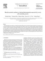
Fig. 1 displays the XRD patterns of the iron oxide precursor syn-
thesized by the hydrothermal reaction of FeCl
3
with H
2
Oat140
◦
C
for 12 h in the presence of Na
2
SO
4
and the products obtained by the
calcination of the precursors at 600
◦
C. In Fig. 1a, all the diffraction
peaks can be indexed as orthorhombic phase of ␣-FeOOH, which
are consistent with the values in the literature (Joint Committee on
Powder Diffraction Standards (JCPDS) card No: 81-0462). Fig. 1b
shows the XRD pattern of the products obtained by the further
annealing of ␣-FeOOH nanostructures at600
◦
C in air for 2 h. Allthe
strong and sharp diffraction peaks can be indexed as the hexagonal
phase of ␣-Fe
2
O
3
(JCPDS card No: 33-0664). No peaks from other
phases are found, suggesting high purity of the as-synthesized ␣-
Fe
2
O
3
.
The morphology and structure of the as-synthesized ␣-FeOOH
precursor were further studied by SEM and TEM, the results are
shown in Fig. 2. SEM image at low magnification (Fig. 2a) shows
that the products consist of a large quantity of microspheres with
typical diameters in the range of 2–4.5 m. The SEM image at high
magnification shown in Fig. 2b reveals that the microsphere is con-
Fig. 1. XRD patterns of (a) theprecursors prepared by thehydrothermal process and
(b) the products obtained by the calcination of the precursors at 600
◦
C.
structed from 1D nanorods with the diameter of about 150 nm.
Fig. 2c shows a typical TEM image of an isolated microsphere,
which indicates that the microsphere is solid and has diameter
of 2m. The basic nanorods are straight and have diameters in
the range of 60–100 nm and lengths of 0.6–1.0 m. Interestingly,
an important phenomenon is found in the TEM observations: a
sheaf of tiny nanorods with diameters of 3 nm are attached side-
by-side into the external sharp end of the constituent “mother”
nanorods, as shown in Fig. 2d. The high-resolution TEM image of
an individual ␣-FeOOH nanorod is displayed in Fig. 2e. The fringe
spacing is about 0.24 and 0.26 nm, corresponding to the (1 11)
and (0 21) crystal planes of the orthorhombic ␣-FeOOH, respec-
tively.
The product obtained by annealing the as-synthesized ␣-FeOOH
nanostructures at 600
◦
C in air for 2 h was characterized by SEM
and TEM, the results are shown in Figs. 3 and 4. SEM observations
show that although ␣-FeOOH was transformed to ␣-Fe
2
O
3
after
the annealing process, the spherical morphology of the products
was almost maintained (Fig. 3a). In addition, we found that the
solid microspheres became into the hollow ones from the half-
baked microsphere shown in the top right corner of Fig. 3a and
that in Fig. 3b. The hollow spheres were built from a single layer of
radially oriented nanorods with a diameter of about 120nm, self-
wrapping to form hollow interior 2 m in diameter (Fig. 3b). This
result was further proven by the following TEM analysis. Fig. 4ais
the TEM image of an individual microsphere. The center portion of
the superstructure is lighter than that of the edge, further confirm-
ing the hollow interiors of the unique self-wrapped nanorod arrays.
The constituent nanorods are in fact a sheaf of tiny nanorods with
diameters of about 5nm (Fig. 4b and c). Fig. 4d is the corresponding
SAED pattern, which clearly indicates thatthe constituent nanorods
were formed by an oriented-growth. The HRTEM image is shown in
Fig. 4e, the measured lattice spacings of 0.27 and 0.37 nm are con-
sistent with the d values of the (1 04) and (01 2) planes of ␣-Fe
2
O
3
with a hexagonal structure, respectively.
In order to understand the formation process of the ␣-FeOOH
nanorod-based microspheres, time-dependent experiments were
carried out and the resultant products were analyzed by SEM and
XRD. The representative SEM images of the products prepared at
140
◦
C for different reaction times are shown in Fig. 5. The SEM
observations show that the products obtained for 15 min consist of
nanorods with diameters of about 60 nm and lengths in the range
of 300–350nm. These nanorods assemble together to form loose
aggregates (Fig. 5b). With an increase on the reaction time, the
92 X. Xie et al. / Journal of Alloys and Compounds 477 (2009) 90–99
Fig. 2. Typical SEM (a, b), TEM (c, d) images and HRTEM (e) image of the ␣-FeOOH nanorod-based microspheres prepared by the hydrothermal process.
constituent nanorods grew further, and thus their diameters and
lengths increased. At the same time, the nanorods self-assembled
further into 3D urchin-like congeries and sphere-like superstruc-
tures as a result of oriented-attachment. When the reaction time
was prolonged to 12 h, the products are entirely composed of the
nanorod-based microspheres (Fig. 1a). Fig. 6 shows XRD patterns
of the products prepared for different reaction times. The XRD
pattern shown in Fig. 6a indicates that the products obtained for
15 min are not well crystallized, and may be amorphous struc-
ture. When the reaction time increased to 8 h, the products are
well crystallize d. All the diffraction peaks shown in Fig. 6b can
be indexed as Fe
8
(OOH)
16
Cl
1.3
(Akaganeite-M) with a monoclinic
structure [22], which are consistent with the values in the litera-
ture (JCPDS No: 42-1315). When the reaction time increase d to 2 h,
in addition to Fe
8
(OOH)
16
Cl
1.3
, ␣-FeOOH with a monoclinic struc-
ture is also formed (Fig. 6c). The Fe
8
(OOH)
16
Cl
1.3
transforms into
␣-FeOOH with an increase on the reaction time (Fig. 6c–e). When
the reaction time was prolonged to 8h, the Fe
8
(OOH)
16
Cl
1.3
are
completely transformed into ␣-FeOOH. When the reaction time is
12 h, the products are composed of the ␣-FeOOH nanorod-based
microspheres (Figs. 1a and 2a). Therefore, it is reasonable to con-
clude that the chemical reactions to form ␣-FeOOH are formulated
X. Xie et al. / Journal of Alloys and Compounds 477 (2009) 90–99 93
Fig. 3. Typical SEM images of the ␣-Fe
2
O
3
hollow microspheres obtained by calcination of ␣-FeOOH microspheres at 600
◦
C.
as follows:
FeCl
3
+ H
2
O → Fe
8
(OOH)
16
Cl
1.3
(1)
Fe
8
(OOH)
16
Cl
1.3
→ ␣-FeOOH + H
2
O + HCl (2)
In addition, the yield also increases with increasing the reaction
time, indicating that formation of Fe
8
(OOH)
16
Cl
1.3
is a slow process
in the presence of Na
2
SO
4
. The as-prepared ␣-FeOOH nanostruc-
tures were heated at 600
◦
C in an air atmosphere to obtain hollow
microspheres constructed with ␣-Fe
2
O
3
nanorods.
As we know, an aggregation process involving the formation of
larger crystals by greatly reducing the interfacial energy of small
primary nanocrystals is energetically favored. However, the inter-
action between unprotected building units with nanoscale size is
generally not competent to form stable and uniform microstruc-
tures [13], such as the sphere-like superstructures discussed here.
Moreover, the building blocks would always randomly aggre-
gate into disordered crystals rather than single crystals in the
absence of sufficiently strong surface-protecting layers. Therefore,
the presence of Na
2
SO
4
was believed to be crucial for the for-
mation of the unique ␣-FeOOH microspheres constructed with
nanorods. To illuminate the role of Na
2
SO
4
in the formation of ␣-
FeOOH nanorod-based microstructures, the products obtained via
a hydrothermal reaction of FeCl
3
with H
2
Oat140
◦
C for 12 h in the
absence of Na
2
SO
4
were characterized with SEM and XRD, and the
results are presented in Fig. 7. The SEM image and XRD pattern
indicated that FeCl
3
reacts with H
2
O without Na
2
SO
4
to form ␣-
Fe
2
O
3
nanocubes with a hexagonal structure instead of ␣-FeOOH
nanorod-based microspheres. Obviously, the advantage is that we
can control the morphology of the products by adding or removing
the sulfate ions. In addition, the IR spectra of ␣-FeOOH nanorod-
based microspheres obtained at 140
◦
C and Na
2
SO
4
powders were
measured, and results are shown in Fig. 8. In the IR spectra the
bands at 1125 and 619 cm
−1
are attributed to SO
4
2−
stretching and
bending vibrations, the broad bands around 3402 and 1632 cm
−1
is ascribed to H
2
O stretching and bending modes, the band at
3160 cm
−1
can be assigned to O-H stretching mode in ␣-FeOOH,
the bands at 893 and 794 cm
−1
are attributed to O–H bending
modes in ␣-FeOOH [23], and the band at 490 cm
−1
was ascribed
to Fe–O stretching vibrations [24]. The IR spectra demonstrate that
there are SO
4
2−
ions on the surface of the constituent ␣-FeOOH
nanorod. In order to further understand the role of Na
2
SO
4
in the
formation of ␣-FeOOH nanorod-based microstructures, the prod-
ucts obtained via a hydrothermal reaction at 140
◦
C for 2 and 12 h
using Fe
2
(SO
4
)
3
as raw material were characterized with SEM and
XRD, and the results are given in Figs. 9 and 10. The SEM images
and XRD patterns reveal that the products obtained for 2 and
12 h are all composed of ␣-FeOOH nanorod-based microspheres.
When the reaction is increase d from 2 to 12 h, the diameters and
lengths of constituent nanorods are increased, and the diameters
of microspheres are increased from 2–2.7 to 4.6–6.8 m. These
results indicate that the formation of ␣-FeOOH nanorod-based
microspheres is the result of SO
4
2−
ions alone. The SO
4
2−
ions sup-
press the further dehydration of ␣-FeOOH and play an important
role in the formation and self-assembly of Fe
8
(OOH)
16
Cl
1.3
and ␣-
FeOOH nanorod into sphere-like superstructures in the aqueous
solution.
In this work, the sphere-like ␣-FeOOH and ␣-Fe
2
O
3
super-
structures were synthesized without using any hard templates
or surfactants. Thus, the formation of sphere-like ␣-FeOOH
superstructures in hydrothermal conditions may be due to the
“oriented-attachment” mechanism [25,26]. On the basis of the
investigations described above, it is possible to interpret the
formation process. The possible formation process of the sphere-
like ␣-FeOOH and ␣-Fe
2
O
3
superstructures is schematically
illustrated in Fig. 11. First, at an early reaction stage, the pri-
mary Fe
8
(OOH)
16
Cl
1.3
nuclei with a amorphous structure were
formed through conventional nucleation. Then, many neighbor-
ing primary Fe
8
(OOH)
16
Cl
1.3
nuclei further grew into the rod-like
nanocrystals with a monoclinic structure through oriented aggre-
gation. Simultaneously, the rod-like nanocrystals gradually evolved
into 3D urchin-like superstructures through oriented-attachment
and self-assembly. Finally the urchin-like superstructures fur-
ther assembled and became dispersed sphere-like superstructures
driven by the minimization of surface energy. The SO
4
2−
ions
play an important role in the formation and self-assembly of
Fe
8
(OOH)
16
Cl
1.3
nanorods into sphere-like superstructures. When
nucleation and growth of Fe
8
(OOH)
16
Cl
1.3
nanocrystallites with an
orthorhombic structure take place in the aqueous solution, SO
4
2−
ions serve as ligand to Fe
3+
, and may adsorb on the facets parallel
to the c-axis of Fe
8
(OOH)
16
Cl
1.3
nuclei by a monodentate structure
(Fe–O–SO
3
) to obtain Fe
8
(OOH)
16
Cl
1.3
nanorods [27]. The pres-
ence of SO
4
2−
ions not only induce formation of Fe
8
(OOH)
16
Cl
1.3
nanorods, but also urge the assembly of Fe
8
(OOH)
16
Cl
1.3
nanorods
into sphere-like superstructures by oriented-attachment process.
The nanorods gradually assemble into 3D urchin-like and spheri-
cal congeries because that bidentate (Fe–O–SO
2
–O–Fe) structure is
formed between Fe
8
(OOH)
16
Cl
1.3
nanorods [27]. During the growth
94 X. Xie et al. / Journal of Alloys and Compounds 477 (2009) 90–99
Fig. 4. Typical TEM images (a–c), SAED pattern (d) and HRTEM image (e) of the ␣-Fe
2
O
3
nanorod-based hollow microspheres.
and self-assembly of Fe
8
(OOH)
16
Cl
1.3
nanorods into urchin-like and
spherical superstructures, the Fe
8
(OOH)
16
Cl
1.3
is gradually decom-
posed into ␣-FeOOH with a monoclinic structure. The ␣-FeOOH
rod-based microspheres grow further into microspheres with a
large size with increasing the reaction time. It is noted that the evo-
lution of Fe
8
(OOH)
16
Cl
1.3
and ␣-FeOOH nanorods into sphere-like
superstructures through oriented-attachment was almost simul-
taneous with their formation and growth. After, the ␣-FeOOH
microspheres are annealed at 600
◦
C in air and transformed into ␣-
Fe
2
O
3
nanorod-based hollow microspheres. During the annealing
process, the ␣-FeOOH was first decomposed to Fe
2
O
3
and H
2
O, the
Fe
2
O
3
nucleated and grew in situ to form ␣-Fe
2
O
3
nanorod-based
hollow microspheres. When Fe
2
(SO
4
)
3
is used as raw material, the
formation of the sphere-like ␣-FeOOH is not from Fe
8
(OOH)
16
Cl
1.3
nanorod-based microspheres, but from directly hydrolysis of Fe
3+
ions in the presence of SO
4
2−
ions. SO
4
2−
ions adsorb on the facets
parallel to the c-axis of the ␣-FeOOH nuclei [27], and their role in
the formation and self-assembly of ␣-FeOOH nanorod into sphere-
X. Xie et al. / Journal of Alloys and Compounds 477 (2009) 90–99 95
Fig. 5. SEM images of the products prepared at 140
◦
C for different reaction times (a) 15 min, (b) 1 h, (c) 2 h, (d) 4 h, (e) 6 h, (f) 8 h.
like superstructures in the aqueous solution is the same with that
of Fe
8
(OOH)
16
Cl
1.3.
Fig. 12 shows the N
2
adsorption/desorption isotherm and the
corresponding pore size distribution of the ␣-Fe
2
O
3
nanorod-
based hollow microspheres. The measurement shows that the BJH
(Barett–Joyner–Halenda) desorption average pore size of these
spheres was ca. 51.0 nm and that the BET surface area was
20.78 m
2
/g.
Powdere d ␣-Fe
2
O
3
and colloidal ␣-Fe
2
O
3
particles have been
found to be active for the water splitting [28] and photodecompo-
sition of phenol and oxalic acid and salicylic acid [29,30]. However,
their efficiencies are quite low. Recently, photocatalytic proper-
ties of ␣-Fe
2
O
3
nanostructures with defined size and shape, such
as ␣-Fe
2
O
3
hollow nanostructures were investigated. The results
demonstrate that the ␣-Fe
2
O
3
hollow spheres were effective pho-
tocatalysts for the degradation of salicylic acid [19] and diethyl
phthalate [20]. Herein, the photocatalytic performance of the
as-synthesized ␣-Fe
2
O
3
nanorod-based microspheres was inves-
tigated in the degradation of methyl orange. We chose the methyl
orange as a target pollutant based on the considerations as follows:
(1) the methyl orange is a good model compound. It is stable under
UV light irradiation and resistant to hydrogen peroxide oxidation.
(2) Dye pollutants are becoming a major source of environmental
contaminant. Azo dye accounts for over 60% of the total number of
96 X. Xie et al. / Journal of Alloys and Compounds 477 (2009) 90–99
Fig. 6. XRD patterns of the samples prepared at 140
◦
C for different reaction times
(a) 15 min, (b) 1 h, (c) 2 h, (d) 4 h, (e) 6 h, (f) 8 h.
dye structures known. These dyes are non-biodegradable and show
a relatively high persistence in soils and aquatic systems.
To evaluate the photocatalytic activity of our products, the
absorption spectra of methyl orange, methyl orange-H
2
O
2
and
methyl orange-H
2
O
2
solutions containing ␣-Fe
2
O
3
hollow spheres
after UV light irradiation for 55 min were measured, and results
is shown in Fig. 13a. Methyl orange shows a maximum absorp-
tion band at 465 nm (curve I in Fig. 13a). The absorption intensity
of the peak was reduced by about 63% in the presence of H
2
O
2
(curve II in Fig. 13a). While the absorption peak disappeared almost
completely in the presence of H
2
O
2
and our products (curve III in
Fig. 13a). The time-dependent absorption spectra of methyl orange
solution containing H
2
O
2
and ␣-Fe
2
O
3
nanostructures catalyst dur-
ing the irradiation are illustrated in Fig. 13b. It can be seen that the
maximum absorbanceat 465nm decreased rapidly withirradiation
time. The decoloration of solution may be due to the destruction of
the dye chromogen. Since no new absorption peak was observed,
the methyl orange has been decomposed. It is obvious that the
hollow ␣-Fe
2
O
3
nanorod-based microspheres were effective pho-
tocatalysts for the direct degradation of methyl orange. The fitting
of absorbance maximum plot versus time indicates an exponen-
tial decay as shown in Fig. 13c. The normalized concentration of
Fig. 8. IR spectra of: (a) Na
2
SO
4
powder and (b) ␣-FeOOH nanorod-based micro-
spheres.
the solution equals the normalized maximum absorbance, so we
use C
0
/C to take place of A
0
/A. The photodegradation of methyl
orange catalyzed by the hollow ␣-Fe
2
O
3
nanorod-based micro-
spheres fits pseudo first-order reaction well, i.e., −dc/dt = Kt,or
ln(C
0
/C)=Kt, where C
0
and C are the initialand actual concentration
of methyl orange, respectively, K is the apparent rate constant of
the degradation. In our experiment, K is found to be 0.030/min. The
photocatalytic properties inthe degradation ofmethyl orange of the
␣-Fe
2
O
3
hollow nanostructures suggest that the products may have
potential application in water treatment. It is generally accepted
that the catalytic process is mainly related to the adsorption and
desorption of molecules on the surface of the catalyst. The high
specific surface area of the ␣-Fe
2
O
3
nanostructures results in more
unsaturated surface coordination sites exposed to the solution. In
addition, the hierarchical structures in the catalyst enable storage
of more molecules. However, the surface area of the as-obtained ␣-
Fe
2
O
3
hollow nanostructures is not very large. Therefore, the size
and porosity of the ␣-Fe
2
O
3
nanostructures were tuned by chang-
ing the preparation method and the thermal treatment conditions
to further enlarge the surface area and photocatalytic performance
of the hollow ␣-Fe
2
O
3
nanostructures. Detailed research is still
under way.
Bulk hematite is weakly ferromagnetic at 298 K witha Néel tem-
perature of 955 K and undergoes a “spin-flop” (Morin) transition at
263 K, in which the magnetic moments change orientation [31].
Nanoparticles, however, often exhibit unusual magnetic behaviors
Fig. 7. SEM image (a) and XRD pattern (b) of the products obtained via a hydrothermal reaction of FeCl
3
with H
2
Oat140
◦
C for 12 h in the absence of Na
2
SO
4
.
X. Xie et al. / Journal of Alloys and Compounds 477 (2009) 90–99 97
Fig. 9. SEM images of the products obtained using Fe
2
(SO
4
)
3
as raw material at 140
◦
C for 2 h (a) and 12 h (b).
Fig. 10. XRD patterns of the products obtained using Fe
2
(SO
4
)
3
as raw material at
140
◦
C for 2 h (a) and 12 h (b).
Fig. 12. Nitrogenadsorption–desorption isotherm and the BJH pore size distribution
curve (inset) for the ␣-Fe
2
O
3
nanorod-based hollow microspheres.
Fig. 11. Schematic illustration of the formation process and shape evolution of ␣-FeOOH and ␣-Fe
2
O
3
nanorod-based microspheres.
98 X. Xie et al. / Journal of Alloys and Compounds 477 (2009) 90–99
different from that of bulk samples, owing to finite size effects
[32]. Herein, we investigated the magnetic property of the
as-synthesized hollow microspheres constructed with ␣-Fe
2
O
3
nanorods. The magnetic hysteresis measurements of ␣-Fe
2
O
3
nanostructureswerecarried outat room temperaturein theapplied
magnetic field from −10 to 10 kOe. Fig. 14 is the hysteresis loop
of the ␣-Fe
2
O
3
superstructures. It can be seen that the satura-
tion is not reached up to the maximum applied magnetic field,
which is similar to the reported cases in literature [33]. The hys-
teresis loop shows a weak ferromagnetic behavior with a remanent
magnetization of 0.071emu g
−1
and a coercivity of 219 Oe at room
temperature. The coercive face of 219 Oe is larger than that of
Fig. 13. (a) absorption spectra of methyl orange (I), methyl orange-H
2
O
2
(II) and
methyl orange-H
2
O
2
solutions containing ␣-Fe
2
O
3
hollow spheres (III) after ultra-
violet irradiation for 55 min (b) absorption spectra of methyl orange-H
2
O
2
solutions
containing ␣-Fe
2
O
3
hollow spheres after UV irradiation with different time and (c)
the fitting of absorbance maximum plot vs. time.
Fig. 14. Hysteresis loop for the ␣-Fe
2
O
3
superstructure at room temperature.
110 Oe for spherical hematite with the diameters of 20–50 nm
[33], and is lower than that of 1510 Oe for ␣-Fe
2
O
3
micro-pine
dendrites [17] and 2279 Oe for cantaloupe-like␣-Fe
2
O
3
superstruc-
tures [13]. It is well known that the magnetization of ferromagnetic
materials is dependent on the morphology and structures of the
samples [33]. Compared to sphericalnanoparticles, theas-prepared
1D nanorod-based microspheres have increased anisotropies in
magnetocrystalline anisotropy, which exerts the influence on their
magnetic properties. The enhanced anisotropy induces large mag-
netic coercivity, where themagneticspins are preferentiallyaligned
the long axis and their reversal to the opposite direction requires
higher energy than that for spheres [5]. Therefore, coercivity of
our products is larger than that of spherical hematite with the
diameters of 20–50 nm. Compared with our samples, Fe
2
O
3
micro-
pine dendrites and cantaloupe-like superstructures have increased
anisotropies in the shape, and thus have higher coercivity.
4. Conclusions
In conclusion, we have successfully obtained hollow micro-
spheres constructed with ␣-Fe
2
O
3
nanorods by a two-step
process, including hydrothermal synthesis of the ␣-FeOOH pre-
cursor at low temperature and a subsequent heating treatment.
SO
4
2−
ions played an important role in the formation of ␣-
FeOOH nanorod-based microstructures. During the synthesis
process, no carbon particle or surfactant was used. This proce-
dure has great advantages in large-scale industrial manufacturing
for a simple hydrothermal process, such as inexpensive raw
materials, high purity, and a high morphology yield of the
products. The as-prepared iron oxide nanomaterials show indis-
putable photocatalytic activity for degradation of methyl orange
and weak ferromagnetic behavior with a remanent magneti-
zation of 0.071emu g
−1
and a coercivity of 219 Oe at room
temperature, and are expected to be useful in many other appli-
cations.
Acknowledgements
We would like to thank Liang Gongying from Xi’an Jiaotong Uni-
versity and Chen Dichun from Xi’an University of Technology for
their helps in measurement of magnetic properties and TEM anal-
ysis, respectively. This work was supported by National Natural
Science Foundation of China (Grant No. 20573072) and Specialized
Research Fund for the Doctoral Program of Higher Education (Grant
No. 20060718010).
X. Xie et al. / Journal of Alloys and Compounds 477 (2009) 90–99 99
References
[1] Y.H. Zheng, Y. Cheng, Y.S. Wang, F. Bao, L.H. Zhou, X.F. Wei, J. Phys. Chem. B 110
(2006) 3093.
[2] K.J. Sreeram, R. Indumathy, A. Rajaram, B.U. Nair, T. Ramasami, Mater. Res. Bull.
41 (2006) 1875.
[3] C.Z. Wu, P. Yin, X. Zhu, C. OuYang, Y. Xie, J. Phys. Chem. B 110 (2006) 17806.
[4] J. Chen, L.N. Xu, W.Y. Li, X.L. Gou, Adv. Mater. 17 (2005) 582.
[5] B. Tang, G.L. Wang, L.H. Zhuo, J.C. Ge, L. Cui, Inorg. Chem. 45 (2006) 5196.
[6] X.G. Wen, S.H. Wang, Y. Ding, Z.L. Wang, S.H. Yang, J. Phys. Chem. B 109 (2005)
215.
[7] Y.Y. Fu, J. Chen, H. Zhang, Chem. Phys. Lett. 350 (2001) 491.
[8] C.J. Jia, L.D. Sun, Z.G. Yan, L.P. You, F. Luo, X.D. Han, Y.C. Pang, Z. Zhang, C.H. Yan,
Angew. Chem. Int. Ed. 44 (2005) 4328.
[9] Z.Y. Sun, H.Q. Yuan, Z.M. Liu, B.X. Han, X.R. Zhang, Adv. Mater. 17 (2005) 2993.
[10] S.B. Wang, Y.L. Min, S.H. Yu, J. Phys. Chem. C 111 (2007) 3551.
[11] J.B. Wu, H. Zhang, N. Du, X.Y. Ma, D.R. Yang, J. Phys. Chem. B 110 (2006) 11196.
[12] L.P. Zhu, H.M. Xiao, X.M. Liu, S.Y. Fu, J. Mater. Chem. 16 (2006) 1794.
[13] L.P. Zhu, H.M. Xiao, S.Y. Fu, Cryst. Growth Des. 7 (2007) 177.
[14] S.Z. Li, H. Zhang, J.B. Wu, X.Y. Ma, D.R. Yang, Cryst. Growth Des. 6 (2006) 351.
[15] L.S. Zhong, J.S. Hu, H.P. Liang, A.M. Cao, W.G. Song, L. Wan, Adv. Mater. 18 (2006)
2426.
[16] S.Y. Zeng, K.B. Tang, T.W. Li, Z.H. Liang, D. Wang, Y.K. Wang, Y.X. Qi, W.W. Zhou,
J. Phys. Chem. C 112 (2008) 4836.
[17] M.H. Cao, T.F. Liu, S. Gao, G.B. Sun, X.L. Wu, C.W. Hu, Z.L. Wang, Angew. Chem.
Int. Ed. 44 (2005) 4197.
[18] J.H. Bang, K.S. Suslick, J. Am. Chem. Soc. 129 (2007) 2242.
[19] L.L. Li, Y. Chu, Y. Liu, L.H. Dong, J. Phys. Chem. C 111 (2007) 2123.
[20] S.Y. Lian, E.B. Wang, L. Gao, D. Wu, Y.L. Song, L. Xu, Mater. Res. Bull. 41 (2006)
1192.
[21] S.W. Cao, Y.J. Zhu, J. Phys. Chem. C 112 (2008) 6253.
[22] Y.H. Hu, Y. Shan, K.Z. Chen, Mater. Res. Bull. 43 (2008) 2703.
[23] S. Krehula, S. Popovi
´
c, S. Music, Mater. Lett. 54 (2002) 108.
[24] A. Sari
´
c, S. Musi
´
c, K. Nomurab, S. Popovic, J. Mol. Struct. 480–481 (1999) 633.
[25] C. Pacholski, A. Kornowski, H. Weller, Angew. Chem. Int. Ed. 41 (2002) 1188.
[26] Z.P. Zhang, H.P. Sun, X.Q. Shao, Adv. Mater. 17 (2005) 42.
[27] Z.Z. Sun, X.M. Feng, W.H. Hou, Nanotechnology 18 (2007) 455607.
[28] I. Cesar, A. Kay, J.G. Martinez, M. Gratzel, J. Am. Chem. Soc. 128 (2006) 4582.
[29] J. Bandara, J.A. Mielczarski, A. Lopez, J. Kiwi, Appl. Catal. B 34 (2001) 321.
[30] B. Pal, M. Sharon, J. Chem. Technol. Biotechnol. 73 (1998) 269.
[31] F. Bødker, M.F. Hansen, Phys. Rev. B 61 (2000) 6 826.
[32] R.H. Kodama, S.A. Makhlouf, A.E. Berkowitz, Phys. Rev. Lett. 79 (1997) 1393.
[33] X.M. Liu, S.Y. Fu, H.M. Xiao, C.J. Huang, J. Solid State Chem. 178 (2005)
2798.