dielectrics in electric fields (2)
Bạn đang xem bản rút gọn của tài liệu. Xem và tải ngay bản đầy đủ của tài liệu tại đây (1.32 MB, 34 trang )
The
rich
and
the
poor
are two
locked caskets
of
which
each contains
the key to
the
other.
Karen Blixen
(Danish
Writer)
1
INTRODUCTORY
CONCEPTS
I
n
this
Chapter
we
recapitulate some basic concepts that
are
used
in
several chapters
that
follow.
Theorems
on
electrostatics
are
included
as an
introduction
to the
study
of
the
influence
of
electric
fields on
dielectric materials.
The
solution
of
Laplace's
equation
to find the
electric
field
within
and
without dielectric combinations yield
expressions which help
to
develop
the
various dielectric theories discussed
in
subsequent
chapters.
The
band theory
of
solids
is
discussed
briefly
to
assist
in
understanding
the
electronic structure
of
dielectrics
and a
fundamental
knowledge
of
this topic
is
essential
to
understand
the
conduction
and
breakdown
in
dielectrics.
The
energy distribution
of
charged particles
is one of the
most basic aspects that
are
required
for a
proper
understanding
of
structure
of the
condensed phase
and
electrical discharges
in
gases.
Certain
theorems
are
merely mentioned without
a
rigorous proof
and the
student should
consult
a
book
on
electrostatics
to
supplement
the
reading.
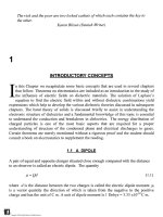
1.1 A
DIPOLE
A
pair
of
equal
and
opposite charges situated close enough compared with
the
distance
to an
observer
is
called
an
electric dipole.
The
quantity
»
=
Qd
(1.1)
where
d is the
distance between
the two
charges
is
called
the
electric dipole
moment,
u.
is
a
vector quantity
the
direction
of
which
is
taken
from
the
negative
to the
positive
•jr.
charge
and has the
unit
of C m. A
unit
of
dipole moment
is 1
Debye
=
3.33
xlO"
C m.
TM
Copyright n 2003 by Marcel Dekker, Inc. All Rights Reserved.
1.2
THE
POTENTIAL
DUE TO A
DIPOLE
Let
two
point charges
of
equal magnitude
and
opposite polarity,
+Q and
-Q
be
situated
d
meters
apart.
It is
required
to
calculate
the
electric potential
at
point
P,
which
is
situated
at
a
distance
of R
from
the
midpoint
of the
axis
of the
dipole.
Let R
+
and R . be the
distance
of the
point
from
the
positive
and
negative charge respectively (fig.
1.1).
Let R
make
an
angle
6
with
the
axis
of the
dipole.
R
Fig.
1.1
Potential
at a far
away
point
P due to a
dipole.
The
potential
at P is
equal
to
Q
R_
(1.2)
Starting
from
this equation
the
potential
due to the
dipole
is
,
QdcosQ
(1.3)
TM
Copyright n 2003 by Marcel Dekker, Inc. All Rights Reserved.
Three other
forms
of
equation (1.3)
are
often
useful.
They
are
(1.4)
(1.5)
(1.6)
The
potential
due to a
dipole decreases more rapidly than that
due to a
single charge
as
the
distance
is
increased. Hence equation (1.3) should
not be
used when
R
«
d. To
determine
its
accuracy relative
to eq.
(1.2) consider
a
point along
the
axis
of the
dipole
at
a
distance
of R=d
from
the
positive charge. Since
6 = 0 in
this case,
(f>
=
Qd/4ns
0
(1.5d)
=Q/9ns
0
d
according
to
(1.3).
If we use
equation (1.2) instead,
the
potential
is
Q/8ns
0
d,
an
error
of
about 12%.
The
electric
field
due to a
dipole
in
spherical coordinates with
two
variables
(r,
0
)
is
given
as:
17
r
n
_!_
n
l-—*r-—*
9
(iy)
Partial
differentiation
of
equation (1.3) leads
to
Equation
(1.7)
may be
written more concisely
as:
TM
Copyright n 2003 by Marcel Dekker, Inc. All Rights Reserved.
(1.10)
Substituting
for
§
from
equation
(1.5)
and
changing
the
variable
to r
from
R we get
1 1
47TGQ
r
r
We
may now
make
the
substitution
r r
3r
^
r
Equation
(1.12)
now
becomes
3//vT
(1.11)
(1.12)
(1.13)
Fig.
1.2
The two
components
of the
electric
field
due to a
dipole with moment
TM
Copyright n 2003 by Marcel Dekker, Inc. All Rights Reserved.
The
electric
field at P has two
components.
The first
term
in
equation
(1.13)
is
along
the
radius vector
(figure
1
.2)
and the
second term
is
along
the
dipole moment. Note that
the
second
term
is
anti-parallel
to the
direction
of
|i.
In
tensor notation equation
(1.13)
is
expressed
as
E=l>
(1.14)
where
T is the
tensor
3rrr"
5
-
r~
3
.
1
.3
DIPOLE MOMENT
OF A
SPHERICAL CHARGE
Consider
a
spherical volume
in
which
a
negative charge
is
uniformly
distributed
and at
the
center
of
which
a
point positive charge
is
situated.
The net
charge
of the
system
is
zero.
It is
clear that,
to
counteract
the
Coulomb
force
of
attraction
the
negative charge
must
be in
continuous motion. When
the
charge sphere
is
located
in a
homogeneous
electric
field E, the
positive charge will
be
attracted
to the
negative plate
and
vice versa.
This introduces
a
dislocation
of the
charge centers, inducing
a
dipole moment
in the
sphere.
The
force
due to the
external
field on the
positive charge
is
(1.15)
in
which
Ze is the
charge
at the
nucleus.
The
Coulomb
force
of
attraction between
the
positive
and
negative charge centers
is
(U6)
in
which
ei
is the
charge
in a
sphere
of
radius
x and
jc
is the
displacement
of
charge
centers. Assuming
a
uniform
distribution
of
electronic charge density within
a
sphere
of
atomic
radius
R the
charge
ei
may be
expressed
as
(1.17)
Substituting equation
(
1
.
1
7)
in
(
1
.
1
6)
we get
TM
Copyright n 2003 by Marcel Dekker, Inc. All Rights Reserved.
(zefx
(1.18)
If
the
applied
field is not
high enough
to
overcome
the
Coulomb
force
of
attraction,
as
will
be the
case
under normal experimental conditions,
an
equilibrium will
be
established
when
F - F'
viz.,
ze-
E =
(ze)
x
(1.19)
The
center
of
the
negative charge
coincides
with
the
nucleus
In
the
presence
of an
Electric
field the
center
of the
electronic
charge
is
shifted
towards
the
positive electrode inducing
a
dipole
moment
in the
atom.
E
Fig.
1.3
Induced dipole moment
in an
atom.
The
electric
field
shifts
the
negative charge center
to
the
left
and the
displacement,
x,
determines
the
magnitude.
The
displacement
is
expressed
as
ze
(1.20)
TM
Copyright n 2003 by Marcel Dekker, Inc. All Rights Reserved.
The
dipole moment induced
in the
sphere
is
therefore
According
to
equation (1.21)
the
dipole moment
of the
spherical charge system
is
proportional
to the
radius
of the
sphere,
at
constant electric
field
intensity.
If we
define
a
quantity, polarizability,
a, as the
induced dipole moment
per
unit electric
field
intensity,
then
a is a
scalar quantity having
the
units
of
Farad meter.
It is
given
by the
expression
?
3
(1.22)
E
1.4
LAPLACE'S EQUATION
In
spherical co-ordinates
(r,0,<j))
Laplace's
equation
is
expressed
as
.
n
^—
—
^
sm6>
—
^
-
-
^
r
2
8r(
dr)
r
2
sm080(
80)
r
2
sin
2
6
80
2
(1-23)
If
there
is
symmetry about
<J)
co-ordinate, then equation (1.23) becomes
8
2
dV
1
8
2
1
8
.
n
dV
„
—
r
—
+
\srn0
—
=0
(1.24)
8r(
dr)
sin6>
80(
80)
v
J
The
general solution
of
equation (1.24)
is
\cos0
(1.25)
in
which
A and B are
constants which
are
determined
by the
boundary conditions.
It is
easy
to
verify
the
solution
by
substituting equation (1.25)
in
(1.24).
The
method
of
finding
the
solution
of
Laplace's
equation
in
some typical examples
is
shown
in the
following sections.
TM
Copyright n 2003 by Marcel Dekker, Inc. All Rights Reserved.
1
.4.1
A
DIELECTRIC SPHERE
IMMERSED
IN A
DIFFERENT MEDIUM
A
typical
problem
in the
application
of
Laplace's equation
towards
dielectric
studies
is
to find the
electric
field
inside
an
uncharged dielectric sphere
of
radius
R and a
dielectric
constant
82. The
sphere
is
situated
in a
dielectric medium extending
to
infinity
and
having
a
dielectric constant
of
S]
and an
external electric
field is
applied along
Z
direction,
as
shown
in figure
1
.4.
Without
the
dielectric
the
potential
at a
point
is,
t/>
= - E Z.
There
are two
distinct regions:
(1)
Region
1
which
is the
space outside
the
dielectric
sphere;
(2)
Region
2
which
is the
space within.
Let the
subscripts
1 and 2
denote
the two
regions, respectively. Since
the
electric
field is
along
Z
direction
the
potential
in
each
region
is
given
by
equation (1.24)
and the
general solution
has the
form
of
equation
(1.25).
Thus
the
potential within
the
sphere
is
denoted
by
^.
The
solutions are:
Region
1:
cos0
(1.26)
V
r
Region
2:
(
B
\
02=L4
2
r
+
-f-
cos0
(1.27)
V
r )
To
determine
the
four
constants
AI
B
2
the
following
boundary conditions
are
applied.
(1)
Choosing
the
center
of the
sphere
as the
origin,
(j)
2
is finite at r = 0.
Hence
B
2
=0
and
<()
2
=A
2
rcos0
(1.28)
(2)
In
region
1
,
at r
->
oo,
^
is due to the
applied
field is
only since
the
influence
of
the
sphere
is
negligible,
i.e.,
=
-Edz
(1.29)
TM
Copyright n 2003 by Marcel Dekker, Inc. All Rights Reserved.
which leads
to
<A
=-Ez
(1.30)
Since
rcos0
= z
equation (1.30) becomes
=-Ercos&
Substituting this
in
equation
(1.26)
yields
A
{
=
- E, and
(1.31)
-±-cos0
r
)
(1.32)
Z
Fig.
1.4
Dielectric sphere embedded
in a
different
material
and an
external
field
is
applied.
(3) The
normal component
of the
flux
density
is
continuous across
the
dielectric
boundary,
i.e.,
at r
=
R,
8£E
~
o22
(1.33)
resulting
in
dr
)r=R
)
r=R
(1.34)
TM
Copyright n 2003 by Marcel Dekker, Inc. All Rights Reserved.
Differentiating
equations (1.28)
and
(1.32)
and
substituting
in
(1.34) yields
(1.35)
V
R )
leading
to
2
(136)
2s
{
(4) The
tangential component
of the
electric
field must
be the
same
on
each side
of the
boundary,
i.e.,
at r = R we
have
§\
-
(j)
2
.
Substituting this condition
in
equation (1.26)
and
(1.28)
and
simplifying
results
in
(1.37)
R
Further
simplification
yields
B
]
=R\A
2
+E)
(1.38)
Equating (1.36)
and
(1.38),
A
2
is
obtained
as
(1.39)
2s
l
+
s
2
Hence
B
}
=R
3
()E
(1.40)
2£
l
+£
2
Substituting equation (1.39)
in
(1.28)
the
potential within
the
dielectric sphere
is
(1.41)
TM
Copyright n 2003 by Marcel Dekker, Inc. All Rights Reserved.
From equation
(1.41)
we
deduce that
the
potential inside
the
sphere varies only with
z,
i.e.,
the
electric
field
within
the
sphere
is
uniform
and
directed along
E.
Further,
dz
-E
(1.42)
(a)
If the
inside
of the
sphere
is a
cavity, i.e.,
s
2
=l
then
E, =
(1.43)
resulting
in an
enhancement
of the field.
(b) If the
sphere
is
situated
in a
vacuum, ie.,
Si=l
then
E,
=
-E
(1.44)
resulting
in a
reduction
of the
field
inside.
Substituting
forA
;
and
B
}
in
equation (1.26)
the
potential
in
region
(1) is
expressed
as
-1
EZ
(1.45)
The
changes
in the
potentials
(j>i
and
(j)
2
are
obviously
due to the
apparent surface charges
on the
dielectric.
If we
represent these changes
as
A(|)i
and
A<))
2
in
region
1 and 2
respectively
by
defining
(1.46)
(1.47)
where
(j)
is the
potential applied
in the
absence
of the
dielectric sphere, then
(1.48)
TM
Copyright n 2003 by Marcel Dekker, Inc. All Rights Reserved.
EZ
(1.49)
Fig.
1
.5
shows
the
variation
of E
2
for
different
values
of
s
2
with respect
to
8]
.
The
increase
in
potential within
the
sphere, equation (1.49), gives rise
to an
electric
field
Az
The
total electric
field
within
the
sphere
is
E
2=
AE
+
E
E
(1.52)
Equation (1.52)
agrees
with equation (1.42)
verifying
the
correctness
of the
solution.
1
.4.2
A
RIGID
DIPOLE
IN A
CAVITY
WITHIN
A
DIELECTRIC
We
now
consider
a
hollow cavity
in a
dielectric material, with
a
rigid dipole
at the
center
and
we
wish
to
calculate
the
electric
field
within
the
cavity.
The
cavity
is
assumed
to be
spherical
with
a
radius
R. A
dipole
is
defined
as
rigid
if its
dipole moment
is not
changed
due
to the
electric
field in
which
it is
situated.
The
material
has a
dielectric constant
8
(Fig. 1.6).
The
boundary
conditions
are:
(1)
((j>i)
r
_>
oo
=
0
because
the
influence
of the
dipole decreases with increasing
distance
from
it
according
to
equation (1.3). Substituting
this
boundary condition
in
equation (1.26) gives
Ai=0
and
therefore
(1.53)
TM
Copyright n 2003 by Marcel Dekker, Inc. All Rights Reserved.
£,
<
£,
t^***&^j$jS,£^)^SSi
5F\
Fig.
1.5
Electric
field
lines
in two
dielectric media.
The
influence
of
relative dielectric constants
of
the two
media
are
shown,
(a)
EI
<
82
(b)
ci
=
82
(c)
BI
> 82
(2)
At any
point
on the
boundary
of the
sphere
the
potential
is the
same whether
we
approach
the
point
from
infinity
or the
center
of the
sphere. This condition gives
(1.54)
leading
to
(1.55)
TM
Copyright n 2003 by Marcel Dekker, Inc. All Rights Reserved.
»
z
Fig.
1.6
A
rigid dipole
at the
center
of a
cavity
in a
dielectric material. There
is no
applied electric
field.
(3) The
normal component
of the flux
density across
the
boundary
is
continuous, expressed
as
=
e
(Ml
r=R
[
dr
)
r=R
(1.56)
Applying this condition
to the
pair
of
equations (1.26)
and
(1.27) leads
to
(1.57)
(4) If the
boundary
of the
sphere
is
moved
far
away i.e.,
R—>oo
the
potental
at
any
point
is
given
by
equation (1.3),
//cos<9
(1.58)
and
TM
Copyright n 2003 by Marcel Dekker, Inc. All Rights Reserved.
4=0
Substituting equations (1.58)
and
(1.59)
in
equation (1.27) results
in
(1.59)
Equation (1.57)
now
becomes
Substituting equation (1.61)
in
(1.55) gives
(1.60)
(1.61)
(1.62)
For
convenience
the
other
two
constants
are
collected here:
(1.60)
The
potential
in the two
regions are:
_
//cos#[
3
427
(1.63)
(1.64)
Let
<j)
r
be the
potential
at r due to the
dipole
in
vacuum.
The
change
in
potential
in the
presence
of the
dielectric sphere
is due to the
presence
of
apparent charges
on the
walls
of
the
sphere. These changes are:
jucostf
<te
0
"
1
2r(l-s)
"
R\2e
+
l)_
TM
Copyright n 2003 by Marcel Dekker, Inc. All Rights Reserved.
2(l-g)//cos6>
2s
+ 1
(1.66)
Since
s is
greater than unity equations (1.63)
and
(1.64) show that there
is a
decrease
in
potential
in
both regions.
The
apparent
surface
charge
has a
dipole moment
|u
a
given
by
2(1
-£)
A,=-
—
r^
(L67)
Equation (1.66) shows that
the
electric
field
in the
cavity
has
increased
by R,
called
the
reaction
field
according
to
R=
2(1}
P
(1-68)
It is
interesting
to
calculate
the
approximate magnitude
of
this
field
at
molecular level.
Substituting
|u
= 1
Debye
= 3.3 x
10"
30
C m, R = 1 x
10"
10
m, and s = 3, the
reaction
field
is
of the
order
of
10
10
V/m
which
is
very high indeed.
The field
reduces rapidly with
distance,
at R = 1 x
10"
9
m, it is
10
7
V/m,
a
reduction
by a
factor
of
1000.
This
is due to
the
fact
that
the
reaction
field
changes according
to the
third power
of R.
The
converse problem
of a
dipole situated
in a
dielectric sphere which
is
immersed
in
vacuum
may be
solved similarly
and the
reaction
field
will then become
R=
(1.69)
If
the
dipole
is
situated
in a
medium that
has a
dielectric constant
of
s
2
and the
dielectric
constant
of
region
1 is
denoted
by
Si
the
reaction
field
within
the
sphere
is
given
by
TM
Copyright n 2003 by Marcel Dekker, Inc. All Rights Reserved.
R
=
2(
V
g2>
H
O-
70
)
47i£
0
s
2
r
(2s
{
+
g
2
)
It
is
easy
to see
that
the
relative values
of
Si
and
s
2
determine
the
magnitude
of the
reaction
field.
The
reaction
field
is
parallel
to the
dipole
moment.
The
general result
for a
dipole within
a
sphere
of
dielectric constant
8
2
surrounded
by a
second dielectric medium
Si
is
£
2
+
2g,
JUCOS0
|
r
2
2r(g
2
-g
t
)
If
6
2
= 1
then these equations reduce
to
equations (1.63)
and
(1.64).
If
R—
»oo
then
<j)
2
reduces
to a
form
given
by
(1.3).
1
.4.3
FIELD
IN A
DIELECTRIC
DUE TO A
CONDUCTING
INCLUSION
When
a
conducting sphere
is
embedded
in a
dielectric
and an
electric
field
E is
applied
the field
outside
the
sphere
is
modified.
The
boundary conditions are:
(1)
At
r—>oo
the
electric
field is due to the
external source
and
^
—
>
-
ErcosO
.
Substituting
this condition
in
equation
(1
.26)
gives
A
}
= -E and
therefore
(
B
^
fa=
\-Er
+
-L
cos<9
(1.71)
V
r )
(2)
Since
the
sphere
is
conducting there
is no field
within.
Let us
assume that
the
surface
potential
is
zero,
i.e.,
This condition when applied
to
equation (1.26) gives
TM
Copyright n 2003 by Marcel Dekker, Inc. All Rights Reserved.
(
R
\
l-ER
+
^r
cos<9
=
0
(1.73)
V
R )
Equation
(1.73)
is
applicable
for all
values
of 6 and
therefore
B^=ER
3
(1.74)
The
potential
in
region
1 is
obtained
as
fa
=-Er
+
=^-
cos0
(1.75)
We
note that
the
presence
of the
inclusion increases
the
potential
by an
amount given
by
the
second term
of the eq.
(1.75). Comparing
it
with equation (1.3)
it is
deduced that
the
increase
in
potential
is
equivalent
to 4
TT
B
O
times
the
potential
due to a
dipole
of
moment
ofvalueER
3
.
1.5
THE
TUNNELING
PHENOMENON
Let
an
electron
of
total energy
s eV be
moving along
x
direction
and the
forces
acting
on
it
are
such that
the
potential energy
in the
region
x < 0 is
zero
(fig.
1.7).
So its
energy
is
entirely
kinetic.
It
encounters
a
potential barrier
of
height
8
po
t
which
is
greater than
its
energy. According
to
classical theory
the
electron cannot overcome
the
potential barrier
and
it
will
be
reflected back, remaining
on the
left
side
of the
barrier. However according
to
quantum mechanics there
is a
finite
probability
for the
electron
to
appear
on the
right
side
of the
barrier.
To
understand
the
situation better
let us
divide
the
region into three parts:
(1)
Region
I
from
which
the
electron approaches
the
barrier.
(2)
Region
II of
thickness
d
which
is the
barrier itself.
(3)
Region
III to the
right
of the
barrier.
The
Schroedinger's
equation
may be
solved
for
each region separately
and the
constants
in
each region
is
adjusted
such that there
are no
discontinuities
as we
move
from
one
region
to the
other.
TM
Copyright n 2003 by Marcel Dekker, Inc. All Rights Reserved.
A
traveling wave encountering
an
obstruction will
be
partly reflected
and
partly
transmitted.
The
reflected wave
in
region
I
will
be in a
direction opposite
to
that
of the
incident wave
and a
lower amplitude though
the
same frequency.
The
superposition
of
the two
waves will result
in a
standing wave pattern.
The
solution
in
this region
is of the
type
!
=
4
exp()
+
A
2
exp(-)
(1
.76)
where
we
have made
the
substitutions:
h 1 2
h
=
—
;
s
=
—mv
;
2
The
first
term
in
equation
(1.76)
is the
incident wave,
in the x
direction;
the
second term
is
the
reflected wave,
in the - x
direction.
Within
the
barrier
the
wave
function
decays exponentially
from
x = 0 to x =
d
according
to:
0<x<d
(1.78)
(1.79)
Since
s
pot
> 8 the
probability density
is
real within
the
region
0
<
jc<
d and the
density
decreases exponentially with
the
barrier thickness.
The
central point
is
that
in the
case
of
a
sufficiently
thin barrier
(< 1
nm)
we
have
a
finite,
though small, probability
of
finding
the
electron
on the
right side
of the
barrier. This phenomenon
is
called
the
tunneling
effect.
The
relative probability that tunneling will occur
is
expressed
as the
transmission
co-
efficient
and
this
is
strongly dependent
on the
energy
difference
(s
po
t-s)
and d.
After
tedious
mathematical manipulations
we get the
transmission
co-efficient
as
TM
Copyright n 2003 by Marcel Dekker, Inc. All Rights Reserved.
T =
exp(-2p
{
d)
(1.80)
in
which/?/
has
already been
defined
in
connection with
eq.
(1.79).
A
co-efficient
of
T=0.01
means that
1% of the
electrons impinging
on the
barrier will tunnel through.
The
remaining
99%
will
be
reflected.
The
tunnel
effect
has
practical applications
in the
tunnel diode, Josephson junction
and
scanning tunneling microscope.
Electron
s
<
s
pft
4k____________*____«_fe
jp__
M
____~._ __
l
~_
1
p
A
1
'
\/
V
"Reflected
-^Ui_~_~«.~~-~ _
«
Transmitted
ni
\/\x
0
Fig.
1.7
An
electron moving
from
the
left
has
zero potential energy.
It
encounters
a
barrier
of
Spot
Volts
and the
electron wave
is
partly reflected
and
partly transmitted.
The
transmitted
wave penetrates
the
barrier
and
appears
on the
right
of the
barrier",
(with permission
of
McGraw Hill Ltd., Boston).
1.6
BAND THEORY
OF
SOLIDS
A
brief description
of the
band theory
of
solids
is
provided here.
For
greater details
standard
text
books
may be
consulted.
1.6.1
ENERGY
BANDS
IN
SOLIDS
If
there
are N
atoms
in a
solid
sufficiently
close
we
cannot ignore
the
interaction between
them, that
is, the
wave
functions
associated with
the
valence electrons
can not be
treated
as
remaining distinct. This means that
the N
wave
functions
combine
in 2N
different
ways.
The
wave
functions
are of the
form
TM
Copyright n 2003 by Marcel Dekker, Inc. All Rights Reserved.
¥\ =
¥i
+ ¥2
+
¥3
¥2
=
¥\
+ ¥2
+
¥3
+ -
¥N
¥2N-\
=
¥\
- ¥2
+
¥3
(1-81)
=
~¥\
+ ¥2
+
¥3
+
+
¥N
Each
orbital
is
associated with
a
particular energy
and we
have
2N
energy levels into
OS
"5
which
the
isolated level
of the
electron splits. Recalling that
N»10
atoms
per
m
the
energy levels
are so
close that they
are
viewed
as an
energy band.
The
energy bands
of a
solid
are
separated
from
each other
in the
same
way
that energy levels
are
separated
from
each other
in the
isolated atom.
1.6.2
THE
FERMI LEVEL
In
a
metal
the
various energy bands overlap resulting
in a
single band which
is
partially
full.
At a
temperature
of
zero Kelvin
the
highest energy level occupied
by
electrons
is
known
as the
Fermi level
and
denoted
by
S
F
.
The
reference
energy level
for
Fermi
energy
is the
bottom
of the
energy band
so
that
the
Fermi
energy
has a
positive value.
The
probability
of
finding
an
electron with energy
s is
given
by the
Fermi-Dirac
statistics according
to
which
we
have
(1.81)
1
+ exp
kT
At c =
S
F
the the
probability
of
finding
the
electron
is
1
A
for all
values
of kT so
that
we
may
also
define
the
Fermi Energy
at
temperature
T as
that energy
at
which
the
probability
of
finding
the
electron
is
Vi
. The
occupied energy levels
and the
probability
are
shown
for
four
temperatures
in
figure
(1.8).
As the
temperature increases
the
probability
extends
to
higher energies.
It is
interesting
to
compare
the
probability given
by
the
Boltzmann classical theory:
(1.82)
The
fundamental
idea that governs these
two
equations
is
that,
in
classical physics
we do
not
have
to
worry about
the
number
of
electrons having
the
same energy. However
in
TM
Copyright n 2003 by Marcel Dekker, Inc. All Rights Reserved.
quantum
mechanics there cannot
be two
electrons having
the
same energy
due to
Pauli's
exclusion principle.
For (e -
C
F
)
»
kT
equation
(1.81)
may be
approximated
to
P(e)
=
exp-
(1-83)
which
has a
similar
form
to the
classical equation
(1.82).
The
elementary band theory
of
solids, when applied
to
semi-conductors
and
insulators,
results
in a
picture
in
which
the
conduction band
and the
valence bands
are
separated
by
a
forbidden
energy
gap
which
is
larger
in
insulators than
in
semi-conductors.
In a
perfect
dielectric
the
forbidden
gap
cannot harbor
any
electrons; however presence
of
impurity
centers
and
structural disorder introduces localized states between
the
conduction band
and
the
valence band. Both holes
and
electron traps
are
possible
3
.
Fig.
1.9
summarizes
the
band theory
of
solids which explains
the
differences
between
conductors, semi-conductors
and
insulators.
A
brief description
is
provided below.
A: In
metals
the
filled
valence band
and the
conduction band
are
separated
by a
forbidden
band which
is
much smaller than
kT
where
k is the
Boltzmann constant
and T
the
absolute temperature.
B:
In
semi-conductors
the
forbidden
band
is
approximately
the
same
as kT.
C:
In
dielectrics
the
forbidden band
is
several electron volts larger than
kT.
Thermal
excitation alone
is not
enough
for
valence electrons
to
jump over
the
forbidden
gap.
D: In
p-type semi-conductor acceptors extend
the
valence band
to
lower
the
forbidden
energy gap.
E: In
n-type semi-conductor donors lower
the
unfilled
conduction band again lowering
the
forbidden energy gap.
F:
In p-n
type semi-conductor both acceptors
and
donors lower
the
energy gap.
An
important point
to
note with regard
to the
band theory
is
that
the
theory assumes
a
periodic
crystal lattice structure.
In
amorphous materials this assumption
is not
justified
and
the
modifications that should
be
incorporated have
a
bearing
on the
theoretical
magnitude
of
current.
The
fundamental
concept
of the
individual energy levels
transforming
into bands
is
still valid because
the
interaction between neighboring atoms
is
still present
in the
amorphous material just
as in a
crystalline lattice. Owing
to
irregularities
in the
lattice
the
edges
of the
energy bands lose their sharp character
and
become rather
foggy
with
a
certain number
of
allowed states appearing
in the
tail
of
each
TM
Copyright n 2003 by Marcel Dekker, Inc. All Rights Reserved.
band.
If the
tail
of the
valence band overlaps
the
tail
of the
conduction band then
the
material behaves
as a
semi-conductor
4
(fig.
1.10).
t
Cfl,
m
i-
<u
a
N
\
0
Probability,
P(s)
Fig.
1.8 The
probability
of
filling
is a
function
of
energy level
and
temperature.
The
probability
of
filling
at the
Fermi energy
is
1
A
for all
temperatures.
As T
increases
P(e)
extends
to
higher energies.
The
amorphous semi-conductor
is
different
from
the
normal semi-conductor because
impurities
do not
substantially
affect
the
conductivity
of the
former.
The
weak
dependence
of
conductivity
on
impurity
is
explained
on the
basis that large fluctuations
exist
in the
local arrangement
of
atoms. This
in
turn will provide
a
large number
of
localized trap levels,
and
impurity
or
not, there
is not
much
difference
in
conductivity.
Considering
the
electron
traps,
we
distinguish between shallow traps closer
to the
conduction band,
and
deep
traps
closer
to the
valence band.
The
electrons
in
shallow
traps have approximately
the
same energy
as
those
in the
conduction band
and are
likely
to be
thermally excited
in to
that band. Electrons
in the
ground state, however,
are
more
likely
to
recombine with
a
free
hole rather than
be
re-excited
to the
conduction band
(fig.
TM
Copyright n 2003 by Marcel Dekker, Inc. All Rights Reserved.
1.9).
The
recombination time
may be
relatively long. Thus electrons
in the
ground state
act
as
though they
are
deep traps
and
recombination centers.
C0NOuCTtG»r
BAWD
/
VALENCt
X
BAND
-
CONDUCTION
BANG
METAL
,COI«>OCTION'
•AND
'
'//////A
BAND
/
VALEMCE
X
8AHO
UNBILLED
'CONDUCTION
BAND
-
BAMO
>
CONDUCTION
•AND
FORBIDDEN
BAND
SEMICOWOUCTOR
CB1
VtLJ
^COKOUCTIOII'
BAND
RAf*Ov
CONOR
LEVELS
UVCLS
IM*»U»ITV
SCMiCOttOUCTOftS
1C)
y
,
8A*0
S
s
S
J
f
(MSUtATO*
to
COMOOCTIOM
f
.SAW
>
Y//////S
FOUBtOOCM
y
»AWO
'***
*
*
MIXED
Fig.
1.9
Band theory
for
conduction
in
metals,
semi-conductors,
and
Insulators
[After
A. H.
Wilson,
Proc.
Roy. Soc.,
A 133
(1931)
458] (with
permission
of the
Royal
Society).
Shallow
traps
and the
ground states
are
separated
by an
energy level which corresponds
to the
Fermi level
in the
excited
state.
This level
is the
steady-state
under excitation.
To
distinguish this level
from
the
Fermi level corresponding
to
that
in the
metal
the
term
'dark
Fermi
level'
has
been used
(Eckertova,
1990). Electrons
in the
Fermi level have
the
same probability
of
being excited
to the
conduction band
or
falling
into
the
ground
state. Free electrons
in the
conduction band
and
free
holes
in the
valence band
can
move
under
the
influence
of an
electric
field,
though
the
mobility
of the
electrons
is
much
TM
Copyright n 2003 by Marcel Dekker, Inc. All Rights Reserved.
higher. Electrons
can
also transfer between localized states, eventually ending
up in the
conduction band. This process
is
known
as
"conduction
by
hopping".
An
electron
transferring
from
a
trap
to
another localized state under
the
influence
of an
electric
field
is
known
as the
Poole-Frenkel
effect.
Fig.
1.11
5
'
6
shows
the
various possible levels
for
both
the
electrons
and the
holes.
N(G)
Fig.
1.10
Energy diagram
of an
amorphous material with
the
valence band
and
conduction band
having
rough edges (Schematic diagram).
1
.6.3
ELECTRON EMISSION FROM
A
METAL
Electrons
can be
released
from
a
metal
by
acquiring energy
from
an
external source.
The
energy
may be in the
form
of
heat,
by
rising
the
temperature
or by
electromagnetic
radiation.
The
following mechanisms
may be
distinguished:
(1)
Thermionic Emission
(Richardson-Bushman
equation):
(1.84)
where
J is the
current density,
(|)
the
work
function,
T the
absolute temperature
and R the
reflection
co-efficient
of the
electron
at the
surface.
The
value
of R
will
depend upon
the
surface
conditions.
B
0
,
called
the
Richardson-Dushman constant,
has a
value
of
1.20
x
10
6
A
m"
2
K"
2
.
The
term
(1-R)B
0
can be as low as 1 x
10
2
A
m'
2
K'
2
.
TM
Copyright n 2003 by Marcel Dekker, Inc. All Rights Reserved.