dielectrics in electric fields (3)
Bạn đang xem bản rút gọn của tài liệu. Xem và tải ngay bản đầy đủ của tài liệu tại đây (2.68 MB, 61 trang )
Seek
simplicity,
and
distrust
it.
-Alfred
North
Whitehead
POLARIZATION
and
STATIC
DIELECTRIC
CONSTANT
T
he
purposes
of
this chapter
are (i) to
develop equations relating
the
macroscopic
properties (dielectric constant, density, etc.) with microscopic quantities such
as
the
atomic radius
and the
dipole moment, (ii)
to
discuss
the
various mechanisms
by
which
a
dielectric
is
polarized when under
the
influence
of a
static electric
field
and
(iii)
to
discuss
the
relation
of the
dielectric constant with
the
refractive
index.
The
earliest
equation relating
the
macroscopic
and
microscopic quantities leads
to the
so-called
Clausius-Mosotti equation
and it may be
derived
by the
approach adopted
in the
previous chapter, i.e.,
finding
an
analytical solution
of the
electric
field.
This leads
to the
concept
of the
internal
field
which
is
higher
than
the
applied
field
for all
dielectrics
except vacuum.
The
study
of the
various mechanisms responsible
for
polarizations lead
to
the
Debye equation
and
Onsager
theory. There
are
important modifications like
Kirkwood
theory which will
be
explained with
sufficient
details
for
practical
applications. Methods
of
Applications
of the
formulas
have been demonstrated
by
choosing relatively simple molecules without
the
necessity
of
advanced knowledge
of
chemistry.
A
comprehensive list
of
formulas
for the
calculation
of the
dielectric constants
is
given
and
the
special
cases
of
heterogeneous media
of
several components
and
liquid mixtures
are
also presented.
2.1
POLARIZATION
AND
DIELECTRIC CONSTANT
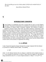
Consider
a
vacuum capacitor consisting
of a
pair
of
parallel electrodes having
an
area
of
cross section
A m
2
and
spaced
d m
apart. When
a
potential
difference
V is
applied
between
the two
electrodes,
the
electric
field
intensity
at any
point between
the
electrodes, perpendicular
to the
plates, neglecting
the
edge
effects,
is
E=V/d.
The
TM
Copyright n 2003 by Marcel Dekker, Inc. All Rights Reserved.
36
Chapter!
capacitance
of the
vacuum capacitor
is Co =
So
A/d and the
charge stored
in the
capacitor
is
Qo=A£oE
(2.1)
in
which
e
0
is the
permittivity
of
free
space.
If
a
homogeneous dielectric
is
introduced between
the
plates keeping
the
potential
constant
the
charge stored
is
given
by
Q
=
s
Q
sAE
(2.2)
where
s is the
dielectric constant
of the
material. Since
s is
always greater than unity
Qi
>
Q and
there
is an
increase
in the
stored charge given
by
*-l)
(2-3)
This
increase
may be
attributed
to the
appearance
of
charges
on the
dielectric surfaces.
Negative charges appear
on the
surface
opposite
to the
positive plate
and
vice-versa (Fig.
2.
1)
1
.
This system
of
charges
is
apparently neutral
and
possesses
a
dipole moment
(2.4)
Since
the
volume
of the
dielectric
is v
=Ad
the
dipole moment
per
unit volume
is
P
=
-^
=
Ee
0
(e-l)
=
X
e
0
E
(2.5)
Ad
The
quantity
P, is the
polarization
of the
dielectric
and
denotes
the
dipole moment
per
fj
_
unit
volume.
It is
expressed
in C/m . The
constant
yj=
(e-1)
is
called
the
susceptability
of
the
medium.
The flux
density
D
defined
by
D =
£
Q
sE
(2.6)
becomes, because
of
equation (2.5),
D =
s
0
£
+ P
(2.7)
TM
Copyright n 2003 by Marcel Dekker, Inc. All Rights Reserved.
Polarization
37
hi±J
bill
bill
Ei±l
hl±Ihl±Jhl±!H±l
till
H±J
bill
EH
3
3
3
3
a
Free
charge
Bound
chorye
Fig.
2.1
Schematic representation
of
dielectric polarization
[von
Hippel,
1954].
(With
permission
of
John
Wiley
&
Sons,
New
York)
Polarization
of a
dielectric
may be
classified according
to
1.
Electronic
or
Optical Polarization
2.
Orientational Polarization
3.
Atomic
or
Ionic Polarization
4.
Interfacial Polarization.
We
shall consider
the
first
three
of
these
in
turn
and the
last mechanism will
be
treated
in
chapter
4.
2.2
ELECTRONIC
POLARIZATION
The
classical view
of the
structure
of the
atom
is
that
the
center
of the
atom
consists
of
positively charged
protons
and
electrically neutral neutrons.
The
electrons move about
the
nucleus
in
closed orbits.
At any
instant
the
electron
and the
nucleus
form
a
dipole
with
a
moment directed
from
the
negative charge
to the
positive charge. However
the
axis
of the
dipole changes with
the
motion
of the
electron
and the
time average
of the
TM
Copyright n 2003 by Marcel Dekker, Inc. All Rights Reserved.
38
Chapter
dipole moment
is
zero. Further,
the
motion
of the
electron must give rise
to
electromagnetic radiation
and
electrical noise.
The
absence
of
such
effects
has led to the
concept that
the
total electronic charge
is
distributed
as a
spherical cloud
the
center
of
which
coincides with
the
nucleus,
the
charge density decreasing with increasing radius
from
the
center.
When
the
atom
is
situated
in an
electric
field
the
charged particles experience
an
electric
force
as a
result
of
which
the
center
of the
negative charge cloud
is
displaced with respect
to the
nucleus.
A
dipole moment
is
induced
in the
atom
and the
atom
is
said
to be
electronically
polarized.
The
electronic polarizability
a
e
may be
calculated
by
making
an
approximation that
the
charge
is
spread
uniformly
in a
spherical
volume
of
radius
R. The
problem
is
then
identical with that
in
section 1.3.
The
dipole moment induced
in the
atom
was
shown
to
be
V
e
=(47re
0
R
3
)E
(1.42)
For
a
given atom
the
quantity inside
the
brackets
is a
constant
and
therefore
the
dipole
moment
is
proportional
to the
applied electric
field.
Of
course
the
dipole moment
is
zero
when
the
field
is
removed since
the
charge centers
are
restored
to the
undisturbed
position.
The
electronic polarizability
of an
atom
is
defined
as the
dipole moment induced
per
unit
electric
field
strength
and is a
measure
of the
ease with which
the
charge centers
may be
SJ
dislocated.
a
e
has the
dimension
of F m .
Dipole moments
are
expressed
in
units called
Debye
whose pioneering studies
in
this
field
have contributed
so
much
for our
present
understanding
of the
behavior
of
dielectrics.
1
Debye
unit
=
3.33
x
10~
30
C
m.
a
e
can be
calculated
to a first
approximation
from
atomic constants.
For
example
the
radius
of a
hydrogen atom
may be
taken
as
0.04
nm
and
ot
e
has a
value
of
10"
41
F
m
2
.
For
a field
strength
of 1
MV/m which
is a
high
field
strength,
the
displacement
of the
negative
charge center, according
to eq.
(1.42)
is
10"
16
m;
when compared with
the
atomic
radius
the
displacement
is
some
10"
5
times smaller. This
is due to the
fact
that
the
internal
electric
field
within
the
atom
is of the
order
of
10
11
V/m
which
the
external
field is
required
to
overcome.
TM
Copyright n 2003 by Marcel Dekker, Inc. All Rights Reserved.
Polarization
39
Table
2.1
Electronic polarizability
of
atoms
2
a
e
Element
radius
(10"
10
m)
(10'
40
F
m
2
)
He
0.93 0.23
Ne
1.12 0.45
Ar
1.54 1.84
Xe
1.9
4.53
I
1.33
6.0
Cs
3.9
66.7
(with
permission
of CRC
Press).
Table
2.1
shows that
the
electronic polarizability
of
rare
gases
is
small because their
electronic structure
is
stable, completely
filled
with
2, 10, 18 and 36
electrons.
As the
radius
of the
atom increases
in any
group
the
electronic polarizability increases
in
accordance with
eq.
(1.42). Unlike
the
rare
gases,
the
polarizability
of
alkali metals
is
more
because
the
electrons
in
these
elements
are
rather loosely bound
to the
nucleus
and
therefore
they
are
displaced relatively easily under
the
same electric
field. In
general
the
polarizability
of
atoms increases
as we
move down
any
group
of
elements
in the
periodic
table because then
the
atomic radius increases.
Fig.
2.2
3
shows
the
electronic polarizability
of
atoms.
The
rare
gas
atoms have
the
lowest
polarizability
and
Group
I
elements; alkali metals have
the
highest polarizability,
due to
the
single electron
in the
outermost orbit.
The
intermediate elements
fall
within
the two
limits with regularity
except
for
aluminum
and
silver.
The
ions
of
atoms
of the
elements have
the
same polarizability
as the
atom that
has the
same
number
of
electrons
as the
ion.
Na
+
has
a
polarizability
of 0.2 x
10"
40
F
m
2
which
is
of the
same order
of
magnitude
as
oc
e
for Ne.
K
+
is
close
to
Argon
and so on. The
polarizability
of the
atoms
is
calculated assuming that
the
shape
of the
electron
is
spherical.
In
case
the
shape
is not
spherical then
a
e
becomes
a
tensor quantity; such
refinement
is not
required
in our
treatment.
Molecules
possess
a
higher
a
e
in
view
of the
much larger electronic clouds that
are
more
easily displaced.
In
considering
the
polarizability
of
molecules
we
should take into
account
the
bond polarizability which changes according
to the
axis
of
symmetry. Table
2.2
2
gives
the
polarizabilities
of
molecules along three principal axes
of
symmetry
in
units
of
10"
40
Fm
2
.
The
mean polarizability
is
defined
as
oc
m
=
(oti
+
ot2
+
0,3)73.
Table
2.3
gives
the
polarizabilities
of
chemical bonds parallel
and
normal
to the
bond axis
and
also
TM
Copyright n 2003 by Marcel Dekker, Inc. All Rights Reserved.
40
Chapter
2
the
mean value
for all
three directions
in
space, calculated according
to
a
m
= (a
11
+ 2
aj_)/3.
The
constant
2
appears
in
this equation because there
are two
mutually
perpendicular
axes
to the
bond axis.
100-
POLARIZABILITY
0.3-
Cs
SrW»
iZr
Luf
0.1-1
C
;%NI
^a«
g.\
^Zn"!
8
1
Ga»
;
I
Isi
,,
\
to
»Sn
T
Pb
!
Bi
AI
*\
^
e
l«.
Sb
*
^^
Kr
Fig.
2.2
Electronic polarizability (F/m
2
)
of the
elements versus
the
atomic
number.
The
values
on the y
axis must
be
multiplied
by the
constant
4nz
0
xlO"
30
.
(Jonscher,
1983:
With permission
of the
Chelsea Dielectric Press, London).
TM
Copyright n 2003 by Marcel Dekker, Inc. All Rights Reserved.
Polarization
41
It
is
easy
to
derive
a
relationship between
the
dielectric constant
and the
electronic
polarizability.
The
dipole moment
of an
atom,
by
definition
of
a
e
,
is
given
by
a
e
E and if
N
is the
number
of
atoms
per
unit volume then
the
dipole moment
per
unit volume
is
Not
e
E. We can
therefore formulate
the
equation
P =
Na
e
E
(2.8)
Substituting equation (2.5)
on the
left
side
and
equation (1.22)
on the
right yields
s
=
47rNR
3
+1
(2.9)
This expression
for the
dielectric constant
in
terms
of N and R is the
starting point
of the
dielectric theory.
We can
consider
a gas at a
given pressure
and
calculate
the
dielectric
constant using equation (2.9)
and
compare
it
with
the
measured value.
For the
same
gas
the
atomic radius
R
remains independent
of gas
pressure
and
therefore
the
quantity
(s-1)
must vary linearly with
N if the
simple theory holds
good
for all
pressures.
Table
2.4
gives measured data
for
hydrogen
at
various
gas
pressures
at
99.93°
C and
compares with
those
calculated
by
using equation
(2.9)
4
.
At low gas
pressures
the
agreement
between
the
measured
and
calculated dielectric constants
is
quite good.
However
at
pressures above
100
M pa
(equivalent
to
1000 atmospheric pressures)
the
calculated values
are
lower
by
more than
5%. The
discrepancy
is due to the
fact
that
at
such high pressures
the
intermolecular
distance becomes comparable
to the
diameter
of
the
molecule
and we can no
longer assume that
the
neighboring molecules
do not
influence
the
polarizability.
Table
2.2
Polarizability
of
molecules
[3]
Molecule
a,
a
2
a
3
a
m
H
2
1.04 0.80 0.80 0.88
O
2
2.57 1.34 1.34 5.25
N
2
O
5.39 2.30 2.30 3.33
CC1
4
11.66 11.66 11.66 11.66
HC1
3.47 2.65 2.65 2.90
(with
permission
from
Chelsea dielectric press).
TM
Copyright n 2003 by Marcel Dekker, Inc. All Rights Reserved.
4
Chapter
2
Table
2.3
Polarizability
of
molecular bonds
[3]
Bond
a||
a_i_
a
m
comments
H-H
1.03 0.80 0.88
N-H
0.64 0.93 0.83
NH
3
C-H
0.88 0.64 0.72 aliphatic
C-C1
4.07 2.31 2.90
C-Br
5.59 3.20
4.0
C-C
2.09 0.02 0.71 aliphatic
C-C
2.50 0.53 1.19 aromatic
C=C
3.17 1.18 1.84
C=0
2.22 0.83 1.33
carbonyl
(with
permission
from
Chelsea dielectric press).
The
increase
in the
electric
field
experienced
by a
molecule
due to the
polarization
of the
surrounding molecules
is
called
the
internal
field,
Ej.
When
the
internal
field
is
taken
into account
the
induced dipole moment
due to
electronic polarizability
is
modified
as
t*
e
=
a&
(2.10)
The
internal
field
is
calculated
as
shown
in the
following section.
2.3
THE
INTERNAL FIELD
To
calculate
the
internal
field
we
imagine
a
small spherical cavity
at the
point where
the
internal
field is
required.
The
result
we
obtain varies according
to the
shape
of the
cavity;
Spherical shape
is the
least
difficult
to
analyze.
The
radius
of the
cavity
is
large enough
in
comparison with
the
atomic dimensions
and yet
small
in
comparison with
the
dimensions
of the
dielectric.
Let us
assume
that
the net
charge
on the
walls
of the
cavity
is
zero
and
there
are no
short
range interactions between
the
molecules
in the
cavity.
The
internal
field, Ej at the
center
of
the
cavity
is the sum of the
contributions
due to
1.
The
electric
field due to the
charges
on the
electrodes
(free
charges),
EI.
2.
The field due to the
bound charges,
E
2
.
3.
The field due to the
charges
on the
inner walls
of the
spherical cavity,
E
3
.
We may
also view that
E
3
is due to the
ends
of
dipoles that terminate
on the
surface
of the
sphere.
We
have shown
in
chapter
1
that
the
polarization
of a
dielectric
P
gives
rise
to a
surface
TM
Copyright n 2003 by Marcel Dekker, Inc. All Rights Reserved.
Polarization
43
charge
density.
Note
the
direction
of
P
n
which
is due to the
negative charge
on the
cavity
wall.
4.
The field due to the
atoms within
the
cavity,
E
4
.
Table
2.4
Measured
and
calculated dielectric constant
[4].
R=91xlO~
12
m
pressure
(MPa)
1.37
4.71
8.92
14.35
22.43
48.50
93.81
124.52
144.39
density
Kg/m
3
0.439
1.482
2.751
4.305
6.484
12.496
20.374
24.504
26.833
N
(m
3
)xlO
,26
2.86
9.82
18.62
29.91
46.80
101.21
195.78
259.86
301.32
equation
(2.9)
1.00266
1.00898
1.01670
1.02628
1.03966
1.07750
1.12840
1.15620
1.17232
(measured)
1.00271
1.00933
1.01769
1.02841
1.04446
1.09615
1.18599
1.24687
1.28625
We
can
express
the
internal
field as the sum of its
components:
E
i
=E
1
+E
2
+E
3
+E
4
The
sum of the field
intensity
E
t
and
E
2
is
equal
to the
external
field,
E=Ej+E
2
(2.11)
(2.12)
E
3
may be
calculated
by
considering
a
small element
of
area
dA on the
surface
of the
cavity (Fig. 2.3).
Let 0 be the
angle between
the
direction
of E and the
charge density
P
n
.
P
n
is the
component
of P
normal
to the
surface, i.e.,
=
Pcos<9
(2.13)
TM
Copyright n 2003 by Marcel Dekker, Inc. All Rights Reserved.
44
Chapter
2
E
Fig.
2.3
Calculation
of the
internal
field
in a
dielectric.
The
charge
on dA is
dq
=
PcosOdA
The
electric
field
at the
center
of the
cavity
due to
charge
dq is
,
PcosQdA
(2.14)
(2.15)
We
are
interested
in
finding
the
field
which
is
parallel
to the
applied
field. The
component
ofdE
3
along
E is
Pcos
2
0dA
(2.16)
All
surface
elements making
an
angle
9
with
the
direction
of E
give rise
to the
same
dE
3
.
The
area
dA is
equal
to
(2.17)
TM
Copyright n 2003 by Marcel Dekker, Inc. All Rights Reserved.
Polarization
45
The
total area
so
situated
is the
area
of the
annular ring having
a
radii
of r and r +
dO.
i.e., Substituting equation
(2.16)
in
(2.17)
gives
(2.18)
Because
of
symmetry
the
components perpendicular
to E
cancel out.
We
therefore
get
^Pcos
6
ES
=
o
2^
0
(2-19)
=
—
(2.20)
The
charge
on the
element considered also gives rise
to an
electric
field
in a
direction
perpendicular
to E and
this component
is
7
' .
.
PcosQsmOdA
dE
sin
9
-
-
-
-
Substituting expression
(2.17)
in
this expression
and
integrating
we get
o
2 ~
Hence
we
consider only
the
parallel component
of
dE
3
'
in
calculating
the
electric
field
according
to
equation
(2.16).
Because
of
symmetry
the
short range
forces
due to the
dipole moments inside
the
cavity
become
zero,
E
4
=
0, for
cubic crystals
and
isotropic materials. Substituting equation
(2.20)
in
(2.
11)
we get
^
(2.21)
J
is
known
as the
Lorentz
field.
Substituting equation (2.5)
in
(2.21)
we get
TM
Copyright n 2003 by Marcel Dekker, Inc. All Rights Reserved.
46
Chapter
F
-Ff
1
O
??"»
JLi
—
\
7
\^^.Z.^y
Since
we
get,
after
some simple algebra
8-1
=
Na
e
=
N
A
a
e
s + 2
3e
Q
3s
Q
V
where
V is the
molar volume, given
by
M/p.
By
definition
N is the
number
of
molecules
per
unit volume.
If p is the
density
(kg/m
3
),
M the
molecular weight
of
dielectric
(kg/mole),
and
N
A
the
Avagadro number, then
Nxy
(2-24)
Substituting equation (2.24)
in
equation (2.23)
we
get,
p
(225)
in
which
R is
called
the
molar
polarizability.
Equation (2.25)
is
known
as the
Clausius-
Mosotti
equation.
The
left
side
of
equation (2.25)
is
often
referred
to as C-M
factor.
In
this equation
all
quantities except
ct
e
may be
measured
and
therefore
the
latter
may be
calculated.
Maxwell deduced
the
relation that
s =
n
2
where
n is the
refractive
index
of the
material.
Substituting this relation
in
equation (2.25),
and
ignoring
for the
time being
the
restriction that applies
to the
Maxwell equation,
the
discussion
of
which
we
shall
postpone
for the
time being,
we get
=
(2.26)
n +2 p
3e
Q
TM
Copyright n 2003 by Marcel Dekker, Inc. All Rights Reserved.
Polarization
47
Combining equations (2.25)
and
(2.26)
we get
(2.27)
e-\
n
2
-\
s + 2
n
z
+2
Equation (2.27)
is
known
as the
Lorentz-Lorenz equation.
It can be
simplified
further
depending upon particular parameters
of the
dielectric under consideration.
For
example,
gases
at low
pressures have
c
«
1 and
equation (2.23)
simplifies
to
(2.28)
If
the
medium
is a
mixture
of
several gases then
2
(2.29)
where
Nj
and
a^
are the
number
and
electronic polarizability
of
each constituent gas.
Equation
(2.23)
is
applicable
for
small densities only, because
of the
assumptions made
in
the
derivation
of
Clausius-Mosotti equation.
The
equation shows that
the
factor
(s - 1) /
(s +2)
increases with
N
linearly assuming that
oc
e
remains constant. This means that
s
should increase with
N
faster
than linearly
and
there
is a
critical density
at
which
E
should
theoretically become
infinity.
Such
a
critical density
is not
observed experimentally
for
gases
and
liquids.
It
is
interesting
to
calculate
the
displacement
of the
electron cloud
in
practical dielectrics.
As an
example, Carbon tetrachloride
(CC1
4
)
has a
dielectric constant
of
2.24
at
20°C
and
has a
density
of
1600
kg/m
3
.
The
molecular weight
is 156 x
10"
3
Kg/mole.
The
number
of
molecules
per m
3
is
given
by
equation (2.24)
as:
160
°
M
156xlO~
3
=
6.2xl0
27
w~
3
TM
Copyright n 2003 by Marcel Dekker, Inc. All Rights Reserved.
48
Chapter
Let
us
assume
an
electric
field
of
IMV/m
which
is
relatively
a
high
field
strength. Since
P =
Nju
= E
£
0
(s
r
-1)
the
induced dipole moment
is
equal
to
10
6
x
8.854
xl(T
12
x
1.24
_
Q
LI
=
-
~
-
=
1.78x10
Cm
6.2
xlO
27
has 74
electrons. Hence each electron-proton pair,
on the
average
has a
dipole
moment
of
(1.78
x
10"
32
)
774=
2.4 x
10~
35
Cm. The
average displacement
of the
electron
cloud
is
obtained
by
dividing
the
dipole moment
by the
electronic charge,
1.5 x
10"
16
m.
This
is
roughly
10"
6
times that
of the
molecular size.
Returning
to
equation (2.25)
a
rearrangement gives
(2.30)
1-pR/M
where
the
molar polarizability
R
refers
to the
compound. Denoting
the
molar
polarizability
and
atomic weight
of
individual atoms
as r and m
respectively
we can put
R
=
Ir
and M = 2m.
Table
2.5
shows
the
application
of
equation (2.30)
to an
organic
molecule.
As
an
example
we
consider
the
molecule
of
heptanol: Formula
CH
3
(CH
2
)s
(CH
2
OH),
p =
824
kg/m
3
(20°C),
b. p. =
176°
C, m. p. =
-34.1°
C.
a
T
=
I a =
(7x1.06
+
16x0.484
+
1x0.67)
x
10'
40
=
15.83
x
10"
40
F/m
2
M=
I m =
7x12.01
+
16x1.01
+
1x16.00
=
116.23
N
A
ct
T
p
/
3s
0
M
=
0.2556,
s =
2.03, Measured
n
2
=
(1.45)
2
= 2. 10
Equation (2.25)
is
accurate
to
about
1%
when applied
to
non-polar polymers.
Fig.
2.4
5
shows
the
variation
of the
dielectric constant with density
in
non-polar polymers
and the
relation that holds
may be
expressed
as
=
0.325 (2.31)
^
'
The
Clausius-Mosotti
function
is
linearly dependent
on the
density.
TM
Copyright n 2003 by Marcel Dekker, Inc. All Rights Reserved.
Polarization
49
Table
2.5
Calculation
of
molar polarizability
of a
compound
6
Atom
structure
a (x
10'
40
Fm
2
)
m
C
1.064 12.01
H
0.484
1.01
O
(alcohol)
0.671 16.00
O(carbonyl) 0.973
O(ether)
0.723
O(ester) 0.722
Si
4.17
28.08
F
(one/carbon)
0.418 19.00
Cl
2.625 35.45
Br
3.901 79.91
I
6.116
126.90
S
3.476 32.06
N
1.1-1.94
14.01
Structural
effects
Double bond
1.733
Triple bond 2.398
3-member
ring
0.71
4-member ring 0.48
(with
permission
from
North
Holland
Co.).
2.4
ORIENTATIONAL POLARIZATION
The
Clausius-Mosotti
equation
is
derived assuming that
the
relative displacement
of
electrons
and
nucleus
is
elastic,
i.e.,
the
dipole moment
is
zero
after
the
applied voltage
is
removed. However molecules
of a
large number
of
substances
possess
a
dipole moment
even
in the
absence
of an
electric
field. In the
derivation
of
equation (2.23)
the
temperature variation
was not
considered, implying that polarization
is
independent
of
temperature. However
the
dielectric constant
of
many dielectrics depends
on the
temperature, even allowing
for
change
of
state.
The
theory
for
calculating
the
dielectric
constant
of
materials
possessing
a
permanent dipole moment
is
given
by
Debye.
Dielectrics,
the
molecules
of
which
possess
a
permanent dipole moment,
are
known
as
polar materials
as
opposed
to
non-polar substances,
the
molecules
of
which
do not
possess
a
permanent dipole moment. Di-atomic molecules like
H
2
,
N
2
,
C\2,
with
homopolar bonds
do not
possess
a
permanent dipole moment.
The
majority
of
molecules
TM
Copyright n 2003 by Marcel Dekker, Inc. All Rights Reserved.
50
Chapter
that
are
formed
out of
dissimilar
elements
are
polar;
the
electrons
in the
valence shell
tend
to
acquire
or
lose some
of the
electronic charge
in the
process
of
formation
of the
molecule. Consequently
the
center
of
gravity
of the
electronic charge
is
displaced with
respect
to the
positive charges
and a
permanent dipole moment arises.
2.1
2,3
<e-l).'pfc+2)
=0.325
2.1
2,0
VARIATION
OF
DIELECTRIC
CONSTANT,
e'
WITH
DENSITY,
p
INEAR
BRANCHED
PQLYETHYLENES
CYCLQ-OCTANE
CYCLOHEPTANE
CYCLOHEXANE
I I I I I I I
I I
I
0.8
0.9
1.0
Fig.
2.4
Linear variation
of
dielectric constant with density
in
non-polar polymers [Link,
1972].
(With
permission
from
North Holland Publishing Co.)
For
example,
in the
elements
of
HC1,
the
outer shell
of a
chlorine atom
has
seven
electrons
and
hydrogen
has
one.
The
chlorine atom,
on
account
of its
high
electronegativity,
appropriates
some
of the
electronic
charge
from
the
hydrogen
atom
with
the
result that
the
chlorine atom becomes negatively charged
and the
hydrogen atom
is
depleted
by the
same amount
of
electronic charge. This induces
a
dipole moment
in the
molecule
directed
from
the
chlorine atom
to the
hydrogen atom.
The
distance between
the
atoms
of
hydrogen
and
chlorine
is
1.28
x
10"
10
m and it
possesses
a
dipole moment
of
1.08D.
Since
the
orientation
of
molecules
in
space
is
completely arbitrary,
the
substance will
not
exhibit
any
polarization
in the
absence
of a
external
field.
Due to the
fact
that
the
electric
TM
Copyright n 2003 by Marcel Dekker, Inc. All Rights Reserved.
Polarization
field
tends
to
orient
the
molecule
and
thermal agitation
is
opposed
to
orientation,
not all
molecules will
be
oriented. There will
be a
preferential orientation, however,
in the
direction
of the
electric
field.
Increased temperature, which opposes
the
alignment,
is
therefore
expected
to
decrease
the
orientational polarization. Experimentally this
fact
has
been
confirmed
for
many polar substances.
If
the
molecule
is
symmetrical
it
will
be
non-polar.
For
example
a
molecule
of
CC>2
has
two
atoms
of
oxygen distributed evenly
on
either side
of a
carbon atom
and
therefore
the
CO
2
molecule
has no
permanent dipole moment. Carbon monoxide, however,
has a
dipole moment. Water molecule
has a
permanent dipole moment because
the O-H
bonds
make
an
angle
of
105° with each other.
Hydrocarbons
are
either
non-polar
or
possess
a
very small
dipole
moment.
But
substitution
of
hydrogen atoms
by
another element changes
the
molecule into polar.
For
example, Benzene
(Ce
H
6
)
is
non-polar,
but
monochlorobenzene
(CeHsCl),
nitrobenzene
(C6H
5
NO2),
and
monoiodobenzene
(C
6
H
5
I)
are all
polar. Similarly
by
replacing
a
hydrogen atom with
a
halogen,
a
non-polar hydrocarbon
may be
transformed into
a
polar
substance.
For
example methane
(CH
4
)
is
non-polar,
but
chloroform
(CHCls)
is
polar.
2.5
DEBYE EQUATIONS
We
have already mentioned that
the
polarization
of the
dielectric
is
zero
in the
absence
of
an
electric
field,
even
for
polar materials, because
the
orientation
of
molecules
is
random
with
all
directions
in
space having equal probability. When
an
external
field is
applied
the
number
of
dipoles confined
to a
solid angle
dQ
that
is
formed
between
6 and 6 +d0
is
given
by the
Boltzmann distribution law:
n(0)
=
A&xp(-—)d&
(2.32)
kT
in
which
u
is the
potential energy
of the
dipole
and dQ is the
solid angle subtended
at the
center corresponding
to the
angle
0,
where
k, is the
Boltzmann constant,
T the
absolute
temperature
and A is a
constant that depends
on the
total number
of
dipoles. Consider
the
surface
area between
the
angles
6 and 6
+dO
on a
sphere
of
radius
r
(fig. 2.5),
ds
=
In
rsmO-rdO
(2.33)
TM
Copyright n 2003 by Marcel Dekker, Inc. All Rights Reserved.
5
Chapter
2
dO-2
TisinGde
Fig.
2.5
Derivation
of the
Debye equation.
The
solid angle
is
dQ.
Since
the
solid angle
is
defined
as
ds/r
2
the
solid angle between
0 and 6 +d0 is
(2.34)
We
recall that
the
total solid angle subtended
at the
center
of the
sphere
is
471
steridians.
This
may be
checked
by the
formula,
The
potential energy
of a
dipole
in an
electric
field
is
v
=
-//£
(2.35)
Since
the
dipoles
in the
solid angle
are
situated
at an
angle
of 6 the
potential
energy
is
reduced
to
u
=
-juE
cos 9
(2.36)
Substituting equations (2.33)
and
(2.34)
in
(2.32)
we get
n(9)
=
AQxp~27rsm0d0
(2.37)
kT
TM
Copyright n 2003 by Marcel Dekker, Inc. All Rights Reserved.
Polarization
53
Since
a
dipole
of
permanent moment
ju
making
an
angle
6
with
the
direction
of the
electric
field
contributes
a
moment
ju
cos 9, the
contribution
of all
dipoles
in
dO'is
equal
to
ju(0)
=
n(0)^cos0
(2.38)
Therefore
the
average moment
per
dipole
in the
direction
of the
electric
field
is
given
by
the
ratio
of the
dipole moment
due to all
molecules divided
by the
number
of
dipoles,
=
Note that
the
average dipole moment cannot
be
calculated
by
dividing equation
(2.38)
by
(2.37), because
we
must consider
all
values
of 6
from
0 to
TC
before
averaging.
Substituting equations (2.37)
and
(2.38)
in
(2.39)
we get
\27rsm0
d0
kT
)
To
avoid long expressions
we
make
the
substitution
x
(2.41)
kT
V
}
and
cos0
= y
(2.42)
The
substitution
simplifies
equation (2.40)
to
TM
Copyright n 2003 by Marcel Dekker, Inc. All Rights Reserved.
54
Chapter
Recalling that
Qxp(xy)
x
XV
e
}
lyexp(xy)dy
=
—~
x
equation (2.43) reduces
to
(2>44)
V
'
(e
x
-e~
x
)
Since
the
first
term
on the
right side
of
equation (2.44)
is
equal
to
coth
x we get
-
=
L(jc)
(2.45)
X
L(x)
is
called
the
Langevin
function
and it was
first
derived
by
Langevin
in
calculating
the
mean magnetic moment
of
molecules having permanent magnetism, where similar
considerations apply.
The
Langevin
function
is
plotted
in
Fig. 2.6.
For
small values
of x,
i.e.,
for low
field
intensities,
the
average moment
in the
direction
of the
field
is
proportional
to the
electric
field.
This
can be
proved
by the
following considerations:
Substituting
the
identities
for the
exponential
function
in
equation (2.44)
we
have
TM
Copyright n 2003 by Marcel Dekker, Inc. All Rights Reserved.
Polarization
55
r
i
A
•*•
e
=l+x+
— + —
2! 3!
e = 1
—.
r
r
—-—
2!
3!
(2.46)
—7J
3 45
(2.47)
For
small values
of
x
higher powers
of x may be
neglected
and the
Langevin
function
may
be
approximated
to
3kT
(2.48)
For
large values
of
x
however, i.e.,
for
high electric
fields
or low
temperatures,
L(x)
has a
maximum
value
of 1,
though such high electric
fields
or low
temperatures
are not
practicable
as the
following example
shows.
0.0
10.0
Fig.
2.6
Langevin
function
with
x
defined according
to eq.
(2.41).
For
small
values
of
x,
L(x)
is
approximately equal
to
x/3.
Let us
consider
the
polarizability
of HC1 in an
electric
field of 150
kV/m.
The
dipole
moment
of HC1
molecule
is
lD=3.3xlO~
30
C m so
that,
at
room temperature
TM
Copyright n 2003 by Marcel Dekker, Inc. All Rights Reserved.
56
Chapter
2
kT
1.38
xlO~
23
x
293
Note that
x is a
dimensionless quantity.
The
Langevin
function
for
this small value
of x,
because
of
approximation (2.48)
is
The
physical significance
of
this parameter
is
that,
on the
average
we can say
that
0.004%
of
molecules
are
oriented
in the
direction
of the
applied
field. At
higher electric
fields
or
lower temperatures
L(JC)
will
be
larger.
Increase
of
electric
field, of
course,
is
equivalent
to
applying higher torque
to the
dipoles. Decrease
of
temperature reduces
the
agitation velocity
of
molecules
and
therefore
rotating them
on
their axis
is
easier.
An
example
is
that
it is
easier
to
make soldiers
who are
standing
in
attention obey
a
command
than people
in a
shopping mall. Table
2.6
gives
L(x)
for
select values
of x
The
field
strength required
to
increase
the
L(x)
to, say
0.2,
may be
calculated with
the
help
of
equation (2.48). Substituting
the
appropriate values
we
obtain
E = 7 x
Iff
V/m,
which
is
very high indeed. Clearly such high
fields
cannot
be
applied
to the
material
without
causing electrical breakdown. Hence
for all
practical purposes equation (2.48)
should
suffice.
Table
2.6
Langevin Function
for
select values
of x
x
coth
jc
L
(jc)
10"
4
10
4
0
0.01 100.003 0.0033
0.1
10.033 0.0333
0.15 6.716 0.0499
0.18
5.615 0.0598
0.21
4.83
0.0698
Since
L(x)
was
defined
as the
ratio
of
JLIQ
/|u
in
equation (2.45)
we can
express equation
(2.48)
as
TM
Copyright n 2003 by Marcel Dekker, Inc. All Rights Reserved.
Polarization
57
3kT
Therefore
the
polarizability
due to
orientational polarization
is
(
2
-
49
>
The
meanings associated with
p,
0
and
^
should
not
create
confusion.
The
former
is the
average contribution
of a
molecule
to the
polarization
of the
dielectric;
the
latter
is its
inherent dipole moment
due to the
molecular structure.
A
real
life
analogy
is
that
\i
represents
the
entire wealth
of a
rich person whereas
fi
0
represents
the
donation
the
person makes
to a
particular charity.
The
latter
can
never exceed
the
former;
in
fact
the
ratio
|iio
/
fi
«
lin
practice
as
already explained.
The
dipole moment
of
many molecules lies,
in the
range
of
0.1-3 Debye units
and
substituting this value
in
equation (2.48) gives
a
value
oto
«
10"
40
F m
2
,
which
is the
same
order
of
magnitude
as the
electronic polarizability.
The
significance
of
equation (2.49)
is
that
although
the
permanent dipole moment
of a
polar molecule
is
some
10
6
times larger
than
the
induced dipole moment
due to
electronic polarization
of
non-polar molecules,
the
contribution
of the
permanent dipole moment
to the
polarization
of the
material
is of
the
same order
of
magnitude, though always higher
(i.e.,
a
0
>
a
e
).
This
is due to the
fact
that
the
measurement
of
dielectric constant involves weak
fields.
The
polarization
of the
dielectric
is
given
by
(2.51)
If
the
dielectric
is a
mixture
of
several components then
the
dielectric constant
is
given
by
E
J
=n
9
P
=
!#////
(2.52)
TM
Copyright n 2003 by Marcel Dekker, Inc. All Rights Reserved.
58
Chapter
2
where
Nj and
Uj
are the
number
and
dipole moment
of
constituent materials respectively.
In
the
above equation
E
should
be
replaced
by Ej,
equation (2.22)
if we
wish
to
include
the
influence
of the
neighboring molecules.
2.6
EXPERIMENTAL
VERIFICATION
OF
DEBYE
EQUATION
In
deriving
the
Debye equation (2.51)
the
dipole moment
due to the
electronic
polarizability
was not
taken into consideration.
The
electric
field
induces polarization
P
e
and
this should
be
added
to the
polarization
due to
orientation.
The
total polarization
of a
polar dielectric
is
therefore
(2.53)
e
3kT
Equation (2.25)
now
becomes
„
£-lM
TV,
(2.54)
,
p
3^
0
1
3kT
For
mixtures
of
polar materials
the
Debye equation becomes
£-1
1
J
=k
{if
=
S
N
i
(a
ei
+^
L
-)
(2.55)
J
V
;
According
to
equation (2.54)
a
plot
of R as a
function
of
1/T
yields
a
straight line with
an
intercept
N
A
a
e
A
e
,
j
and
a
slope
A
^
(2.56)
Fig.
2.7
shows results
of
measurements
of C-M
factor
as a
function
of 1/T for
silicone
fluids
7
.
Silicone
fluid,
also known
as
poly(dimemyl
siloxane)
has the
formula
(CH
3
)
3
Si
-
[OSi(CH
3
)
2
],
OSi(CH
3
)
3
.
It has a
molecular weight (162.2+72.2
x) g
/mole,
x = 1 to
TM
Copyright n 2003 by Marcel Dekker, Inc. All Rights Reserved.
Polarization
59
•^
1000
and an
average density
of 960
kg/m
. The
advantage
of
using silicone
fluid
is
that
liquids
of
various viscosities with
the
same molecular weight
can be
used
to
examine
the
influence
of
temperature
on the
dielectric constant.
The
polarizabilities
calculated
from
the
intercept
is 1.6 x
10"
37
,
2.9 x
10'
37
,
and 3.7 x
10'
37
Fm
2
for
200,
500 and
1000
cSt
viscosity. These
are the sum of the
electronic
and
atomic polarizabilities.
The
calculated
a
e
using data
from
Table
5
for
a
monomer
(x
=
1,
No. of
atoms:
C - 8, H - 24, Si - 3, O
- 2) is 3.4 x
10"
39
F
m
2
.
For an
average value
of
jc
=
100
(for transformer grade
x = 40)
electronic polarizability alone
has a
value
of the
same order mentioned above
and the
liquid
is
therefore slightly polar.
The
slopes give
a
Dipole moment
of
5.14,
8.3 and 9.4 D
respectively. Sutton
and
Mark
8
give
a
dipole moment
of
8.47
D for 300 cSt
fluid
which
is in
reasonable agreement with
the
value
for 200
cSt.
Application
of
Onsagers
theory (see
section
2.8)
to
these
liquids
gives
a
value
for the
dipole moment
of
8.62, 12.1
and
13.1
D
respectively.
To
obtain
agreement
of the
dipole moment obtained
from fig. 2.7 and
theory,
a
correlation
factor
of
g
=
2.8,
2.1
and 2.1 are
employed, respectively.
•ea
eSt
•34
3Ȥ
HO
Fig.
2.7
Molar polarizability
in
silicone
fluids
versus
temperature
for
various
viscosities
(Raju,
©1988,
IEEE.).
Fig.
2.8
shows
the
calculated
R-T
variation
for
some organic liquids using
the
data
shown
in
Table 2.7. From plots similar
to fig. 2.8 we can
separate
the
electronic
polarizability
and the
permanent dipole moment.
For
non-polar molecules
the
slope
is
zero because,
11
= 0.
TM
Copyright n 2003 by Marcel Dekker, Inc. All Rights Reserved.