dielectrics in electric fields (8)
Bạn đang xem bản rút gọn của tài liệu. Xem và tải ngay bản đầy đủ của tài liệu tại đây (2.51 MB, 54 trang )
FIELD ENHANCED CONDUCTION
T
he
dielectric properties which
we
have discussed
so far
mainly consider
the
influence
of
temperature
and
frequency
on
&'
and
s"
and
relate
the
observed
variation
to the
structure
and
morphology
by
invoking
the
concept
of
dielectric
relaxation.
The
magnitude
of the
macroscopic electric
field
which
we
considered
was
necessarily
low
since
the
voltage applied
for
measuring
the
dielectric constant
and
loss
factor
are in the
range
of a few
volts.
We
shift
our
orientation
to
high electric fields, which implies that
the
frequency
under
discussion
is the
power frequency which
is 50 Hz or 60 Hz, as the
case
may be.
Since
the
conduction
processes
are
independent
of
frequency
only direct
fields
are
considered
except where
the
discussion demands reference
to
higher frequencies. Conduction
current experiments under high electric
fields
are
usually carried
out on
thin
films
because
the
voltages
required
are low and
structurally more
uniform
samples
are
easily
obtained.
In
this chapter
we
describe
the
various conduction mechanisms
and
refer
to
experimental data where
the
theories
are
applied.
To
limit
the
scope
of
consideration
photoelectric conduction
is not
included.
7.1
SOME GENERAL COMMENTS
Application
of a
reasonably high voltage
-500-1000V
to a
dielectric generates
a
current
and
let's
define
the
macroscopic conductivity,
for
limited purposes, using
Ohm's
law.
The dc
conductivity
is
given
by the
simple
expression
C7=—
AE
TM
Copyright n 2003 by Marcel Dekker, Inc. All Rights Reserved.
330
Chapter?
where
a is the
conductivity expressed
in
(Q
m)"
1
,
A the
area
in
m
2
,
and E the
electric
field
in V
m"
1
.
The
relationship
of the
conductivity
to the
dielectric constant
has not
been
theoretically
derived though this relationship
has
been noted
for a
long time.
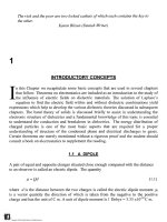
Fig.
7.1
shows
a
collection
of
data
1
for a
range
of
materials
from
gases
to
metals with
the
dielectric constant varying over
four
orders
of
magnitude,
and the
temperature
from
15K
to
3000K. Note
the
change
in
resistivity which ranges
from
10
26
to
10~
14
Q
m.
Three
linear relationships
are
relationship
is
given
as
noticed
in
barest conformity.
For
good
conductors
the
log
p +
3
log
e'
=
7.7
For
poor conductors, semi-conductors
and
insulators
the
relationship
is
(7.2)
2
O
I
2
X
o
>-"
H
>
(/>
</>
UJ
(E
TITANATES
FERRO-ELECTRICS
©
CARBON
AT 0°C
GRAPHITE
AT 0°C
COPPER
AT
500°C
SILVER
AT
15°
K
GLYCERINE
/
AT
800°
C
Sn-Bi
TUNGSTEN
AT
3500°K
/
SILVER
AT
0°C
SUPERCONDUCTORS
COPPER
AT
15°
K
(7.3)
I0
2
I0
3
I0
4
DIELECTRIC
CONSTANT
Fig.
7.1
Relationship between resistivity
and
dielectric constant
(Saums
and
Pendleton, 1978,
with
permission
of
Haydon Book Co.)
Ferro-electrics
fall
outside
the
range
by a
wide margin.
The
region separating
the
insulators
and
semi-conductors
is
said
to
show
"shot-gun"
effect.
Ceramics have
a
higher dielectric constant than that given
by
equation (7.3) while organic insulators have
lower dielectric constant. Gases
are
asymptotic
to the
y-axis with very large resistivity
and
s' is
close
to
one. Ionized
gases
have resistivity
in the
semi-conductor region.
TM
Copyright n 2003 by Marcel Dekker, Inc. All Rights Reserved.
From
the
definition
of
complex dielectric constant
(ch.
3), we
recall
the
following
relationships (Table
7.1):
Table
7.1
Summary
of
definitions
for
current
in
alternating voltage
Quantity
Charging current,
I
c
Loss current,
I
L
Total current,
I
Dissipation
factor,
tan8
Power loss,
P
Formula
CO
C
0
8'
V
coC
0
s"V
co
C
0
V(s'
2
+
e"
2
)
1/2
8"
/
8'
coC
0
e'V
2
tan5
Units
amperes
amperes
amperes
none
Watts
7.2
MOTION
OF
CHARGE CARRIERS
IN
DIELECTRICS
Mobility
of
charge carriers
in
solids
is
quite small,
in
contrast
to
that
in
gases,
because
of
the
frequent
collision with
the
atoms
of the
lattice.
The
frequent
exchange
of
energy
does
not
permit
the
charges
to
acquire energy rapidly, unlike
in
gases.
The
electrons
are
trapped
and
then released
from
localized centers reducing
the
drift
velocity. Since
the
mobility
is
defined
by
W
e
=
jj,
e
E
where
W
e
is the
drift
velocity,
|n
e
the
mobility
and E the
electric
field, the
mobility
is
also reduced
due to
trapping.
If the
mobility
is
less than
~5xlO~
4
m
2
/ Vs the
effective
mean
free
path
is
shorter than
the
mean distance between
atoms
in the
lattice, which
is not
possible
in
principle.
In
this situation
the
concept
of the
mean
free
path cannot hold.
Electrons
can be
injected into
a
solid
by a
number
of
different
mechanisms
and the
drift
of
these charges constitutes
a
current.
In
trap
free
solids
the
Ohmic
conduction arises
as
a
result
of
conduction electrons moving
in the
lattice
of
conductors
and
semi-conductors.
In
the
absence
of
electric
field the
conduction electrons
are
scattered
freely
in a
solid
due
to
their thermal energy. Collision occurs with lattice atoms, crystal imperfections
and
impurity
atoms,
the
average velocity
of
electrons
is
zero
and
there
is no
current.
The
mean
kinetic
energy
of the
electrons will, however, depend
on the
temperature
of the
lattice,
and the
rms
speed
of the
electrons
is
given
by
(3kT/m)
L2
.
If
an
electric
field, E, is
applied
the
force
on the
electron
is
—eE
and it is
accelerated
in
direction opposite
to the
electric
field due to its
negative charge. There
is a net
drift
velocity
and the
current density
is
given
by
TM
Copyright n 2003 by Marcel Dekker, Inc. All Rights Reserved.
(7.4)
a
where
N
e
is the
number
of
electrons,
\\.
the
electron mobility,
V the
voltage
and d the
thickness.
We
first
consider
Ohmic
conduction
in an
insulator that
is
trap
free. The
concept
of
collision time,
i
c
,
is
useful
in
visualizing
the
motion
of
electrons
in the
solid.
It is
defined
as the
time interval between
two
successive collisions which
is
obviously related
to the
mobility according
to
jU
=
eT
c
m*
(7.5)
where
m* is the
effective
mass
of the
electron which
is
approximately equal
to the
free
electron mass
at
room temperature.
The
charge carrier gains energy
from
the field and
loses energy
by
collision with lattice
atoms
and
molecules. Interaction with other charges, impurities
and
defects also results
in
loss
of
energy.
The
acceleration
of
charges
is
given
by the
relationship,
a =
F/m*
= e
E/m*
where
the
effective
mass
is
related
to the
bandwidth
W
b
.
To
understand
the
significance
of the
band
width
we
have
to
divert
our
attention
briefly
to the
so-called
Debye characteristic
temperature
2
.
In
the
early experiments
of the
ninteenth century, Dulong
and
Petit observed that
the
specific
heat,
C
v
,
was
approximately
the
same
for all
materials
at
room temperature,
25
J/mole-K.
In
other words
the
amount
of
heat energy required
per
molecule
to
raise
the
temperature
of a
solid
is the
same regardless
of the
chemical nature.
As an
example
consider
the
specific
heat
of
aluminum which
is 0.9
J/gm-K.
The
atomic weight
of
aluminum
is
26.98
g/mole
giving
C
v
= 0.9 x
26.98
= 24
J/mole-K.
The
specifc
heat
of
iron
is
0.44 J/gm-K
and an
atomic weight
of
55.85 giving
C
v
=
0.44
x
55.85
= 25
J/mole-K.
On the
basis
of the
classical statistical ideas,
it was
shown that
C
v
= 3 R
where
R is the
universal
gas
constant
(= 8.4
J/g-K). This
law is
known
as
Dulong-Petit
law
(1819).
Subsequent experiments showed that
the
specific
heat varies
as the
temperature
is
lowered,
ranging
all the way
from
zero
to 25
J/mole-K,
and
near absolute zero
the
specific
heat varies
as T
3
.
Debye
successfully
developed
a
theory that explains
the
increase
of
C
v
as T is
increased,
by
taking into account
the
coupling
that exists between
individual
atoms
in a
solid instead
of
assuming that each atom
is a
independent vibrator,
TM
Copyright n 2003 by Marcel Dekker, Inc. All Rights Reserved.
as the
earlier approaches
had
done.
His
theory
defined
a
characteristic temperature
for
each material,
0, at
which
the
specific
heat
is the
same.
The new
relationship
is
C
v
(0) =
2.856R.
0 is
called
the
Debye characteristic temperature.
For
aluminum
0 = 395 K, for
iron
0 = 465 K and for
silver
0 = 210 K.
Debye theory
for
specific heat employs
the
Boltzmann
equation
and is
considered
to be a
classical example
of the
applicability
of
Boltzmann
distribution
to
quantum systems.
Returning
now to the
bandwidth
of the
solids,
W
b
may be
smaller
or
greater than
k0.
Wide
bandwidth
is
defined
as Wb > k0 in
contrast
with narrow bandwidth where
Wb <
k0. In
materials with narrow bandwidth
the
effective
mass
is
high
and the
electric
field
produces
a
relatively slow
response.
The
mobility
is
correspondingly lower.
The
band theory
of
solids
is
valid
for
crystalline structure
in
which there
is
long range
order with atoms arranged
in a
regular lattice.
In
order that
we may
apply
the
conventional band theory
a
number
of
conditions should
be
satisfied (Seanor, 1972).
1
.
According
to the
band theory
the
mobility
is
given
by
V-V
1
(7.6)
l/2
3xlQ
2
(27rm*kT)
where
A,
is the
mean
free
path
of
charge carriers which must
be
greater than
the
lattice
spacing
for a
collision
to
occur. This
may be
expressed
as
,m*.
(7.7)
where
m
e
is the
mass
of the
electron
(9.1
x
10"
31
kg) and a the
lattice spacing.
2. The
mean
free
path should
be
greater than electron wavelength
(1
eV =
2.42
x
10
14
Hz
=
1.3
jim).
This condition translates into
the
condition that
the
relaxation time
T
should
be
greater than
(h/2-nkT\
2.5 x
10"
14
s at
room
temperature,
i
is
related
to
ji
according
to
equation (7.5).
3.
Application
of the
uncertainty principle yields
the
condition that
p,
> (e a
W^nhkT).
For
a
lattice spacing
of 50 nm we get
|i
> 3.8
Wb/kT.
If
these conditions
are not
satisfied
then
the
conventional band theory
for the
mobility
can
not be
applied.
The
charge carrier then spends more time
in
localized states than
in
motion
and we
have
to
invoke
the
mechanism
of
hopping
or
tunneling between localized
states.
Charge carriers
in
many molecular crystals show
a
mobility greater than
5 x
10"
4
TM
Copyright n 2003 by Marcel Dekker, Inc. All Rights Reserved.
m
2
V
s"
1
and
varies
as
T
15
.
This large value
of
mobility
is
considered
to
mean that
the
band theory
of
solids
is
applicable
to the
ordered crystal
and
that traps exist within
the
bulk.
The
Einstein equation
D/|ii
-
kT/eV where
D is the
diffusion
co-efficient
may
often
be
used
to
obtain
an
approximate value
of the
mobility
of
charge carriers.
For
most
-23
polymers
a
typical value
is D
=
1 x
10"
m s" and
substituting
k
=
1.38
x 10"
J/K,
e =
1.6 x
10"
19
C
and T = 300 K we get
|n
= 4 x
10"
11
m
2
V'V
1
which
is in the
range
of
values
given
in
Table 7.2.
Table
7.2
Mobility
of
charge carrier
in
polymers [Seanor, 1972]
polymer
Mobility
(x
10'
8
m
2
Vs'
1
)
Activation energy (eV)
Poly(vinyl
chloride)
Acrylonitrile
vinylpyridine
copolymer
Poly-N-inyl
carbazole
Polyethylene
Poly(ethylene terephthalate)
Poly(methyl
methacrylate)
Commercial
PMMA
Poly-n-
butyl-methacrylate
Lucite
Polystyrene
Butvar
Vitel
polyisoprene
Silicone
Poly(vinyl acetate)
Below
TO
Above
T
G
7
3
10'
3
-10"
2
io-
3
IxlO'
2
2.5 x
10'
7
3.6 x
10'
7
2.5 x
10'
6
3.5 x
10'
9
1.4
x
10'
7
4.85
x
IO"
7
4.0 x
IO"
7
2.0 x
IO"
8
3.0 x
IO"
10
2.2 x
10'
8
0.4-0.52
0.24(Tanaka,
1973)
0.24(Tanaka,
1973)
0.52
±
0.09
0.48
±
0.09
0.65
±
0.09
0.52
±
0.09
0.69
±
0.09
0.74
±
0.09
1.08 ±0.13
1.08 ±0.13
1.73
±0.17
0.48
±
0.09
1.21
±0.09
(with permission
from
North Holland Publishing Co.)
This brief discussion
of
mobility
may be
summarized
as
follows.
If the
mobility
of
charge carriers
is
greater than
5 x
IO"
4
m
2
V
s"
1
and
varies
as
T"
n
the
band theory
may be
applied. Otherwise
we
have
to
invoke
the
hopping model
or
tunneling between localized
states
as the
charge spends more time
in
localized
states
than
in
motion.
The
temperature
dependence
of
mobility
is
according
to exp
(-E^
/
kT).
If the
charge carrier spends more
time
at a
lattice site than
the
vibration
frequency
the
lattice will have time
to
relax
and
TM
Copyright n 2003 by Marcel Dekker, Inc. All Rights Reserved.
within
the
vicinity
of the
charge there will
be
polarization.
The
charge
is
called
a
polaron
and the
hopping charge
to
another site
is
called
the
hopping model
of
conduction. Methods
of
obtaining mobilities
and
their limitations have been commented
upom
by
Ku
and
Lepins (1987), and, Hilczer
and
Malecki
(1986).
Table
7.3
shows
the
wide
range
of
mobility reported
in
polyethylene.
Table
7.3
Selected
Mobility
in
polyethylene
3
Mobility
(x
10'
8
m
2
Vs"')
l.Ox
10'
7
(20°C)
1.6xlO"
5
(70°C)
2.2xlO'
4
(90°C)
500
lOtolxlO"
5
l.Ox
10'
7
l.Ox
10'
8
(20°C)
4.2x10'
7
(50°C)
2.3xlO'
6
(70°C)
Author
Wintle
(1972)
1
Davies
(1972)
2
Davies(1972)
3
Tanaka
(1973)
4
Tanaka
and
Calderwood
(1974)
5
Pelissouet.
al.
(1988)
6
Nathet.
al.
(1990)
7
Lee et. al.
(1997)
8
Leeet.
al.
(1997)
Glaram
has
described trapping
of
charge carriers
in a
non-polar
polymer
4
.
The
charge
moves
in the
conduction band along
a
long chain
as far as it
experiences
the
electric
field.
At a
bend
or
kink
if
there
is no
component
of the
electric
field
along
the
chain,
the
charge
is
trapped
as it
cannot
be
accelerated
in the new
direction.
The
trapping site
is
effectively
a
localized
state
and the
charge
stops
there,
spending
a
considerable
amount
of
time. Greater energy, which
may be
available
due to
thermal fluctuations,
is
required
to
release
the
charge
out of its
potential well into
the
conduction band again.
In the
trapped state there
is
polarization
and
therefore some correspondence
is
expected
between conductivity
and the
dielectric constant
as
shown
in
Fig.
7.1.
1
H. J.
Wintle,
J.
Appl.
Phys.,
43
(1972
)
2927).
2
Quoted
in
Tanaka
and
Calderwood (1974).
3
Quoted
in
Tanaka
and
Calderwood
(1974).
4
T.
Tanaka,
J.
Appl.
Phys.,
44
(1973)
2430.
5
T.
Tanaka
and J. H.
Calderwood,
7
(1974)
1295
6
S.
Pelissou,
H.
St-Onge
and M. R.
Wertheimer,
IEEE
Trans.
Elec.
Insu.
23
(1988)
325.
7
R.
Nath,
T.
Kaura,
M. M.
Perlman,
IEEE
Trans. Elec.
Insu.
25
(1990)
419
8
S. H.
Lee,
J.
Park,
C. R. Lee and K. S.
Luh, IEEE Trans.
Diel.
Elec.
Insul.,
4
(1997)
425
TM
Copyright n 2003 by Marcel Dekker, Inc. All Rights Reserved.
A
brief comment
is
appropriate here with regard
to the low
values
of
mobility shown
in
Table 7.2.
The
various energy levels
in a
dielectric with traps
are
shown
in
Fig. 7.2.
For
simplicity only
the
traps below
the
conduction band
are
shown.
The
conduction band
and
the
valence band have energy levels
E
c
and
E
v
respectively.
The
Fermi level,
E
F
,
lies
in
the
energy
gap
somewhere
in
between
the
conduction band
and
valence band.
Generally speaking
the
Fermi level
is
shifted
towards
the
valence band
so
that
E
F
<
Vz
(E
c
-
E
v
).
We
have already seen that
the
Fermi level
in a
metal lies
in the
middle
of the
two
bands,
so
that
the
relation
E
F
=
Vz
(E
c
-
E
v
)
holds.
The
trap level assumed
to be the
same
for all
traps
is
shown
by
E
t
and the
width
of
trap levels
is
AE
t
=
E
c
-E
t
.
Using
Fermi-Dirac
statistics
the
ratio
of the
number
of
free
carriers
in the
conduction
band,
n
c
,
and in the
traps,
n,
is
obtained
as
[Dissado
and
Fothergill,
1992]
n
(7.8)
^
^
where
N
e
ff
and
N
t
is the
effective
number density
of
states
in the
conduction band,
and
the
number density
of
states
in the
trap level, respectively.
The
ratio
n
t
n
c
+n
t
n
t
»n
c
(7.9)
is
the
fraction
of
charge carriers that determines
the
current density. Obviously
the
current will
be
higher without traps
as the
ratio will
be
unity. This ratio
will
be
referred
to in the
subsection (7.4.6)
on
space charge limited current
in
insulators with traps.
Equation
(7.8) determines
the
conductivity
in a
solid with traps present
in the
bulk.
The
change
in
conductivity
due to a
change
in
temperature,
T, may be
attributed
to a
change
in
mobility
by
invoking
a
thermally activated mobility according
to
E
-E,\
(7.10)
In
an
insulator
it is
obvious that
the
number
of
carriers
in the
conduction band,
n
c
,
is
much lower than those
in the
traps,
n
t
,
and the
ratio
on the
left
side
of
equation (7.8)
is
in
the
range
of
10"
6
to
10"
10
.
The
mobility
is
'unfairly'
blamed
for the
resulting
reduction
in the
current
and the
mobility
is
called trap
limited.
We
will
see
later, during
TM
Copyright n 2003 by Marcel Dekker, Inc. All Rights Reserved.
the
discussion
of
space charge currents that this blame
is
balanced
by
crediting mobility
for
an
increase
in
current
by
calling
it
field
dependent.
CONDUCTION
BAND
£«
E,
E
v
VALENCE
BAND
Fig.
7.2 A
simplified diagram
of
energy levels with trap energy being closer
to
conduction level.
There
is a
minimum value
for the
mobility
for
conduction
to
occur according
to the
band
theory
of
solids.
Ritsko
5
has
shown that this
minimum
mobility
is
given
by
In
e
a
2
where
a is the
lattice spacing.
For a
spacing
of the
order
of 1 run the
minimum mobility,
according
to
this expression,
is
~10"
4
m
2
Vs"
1
which
is
about
6-10
orders
of
magnitude
higher than
the
mobilities shown
in
Table
7.1.
Dissado
and
Fothergill (1992) attribute
this
to the
fact
that transport occurs within interchain
of the
molecule rather than within
intrachain.
The
mobilitiy
of
electrons
in
polymers
is ~
10"'°
m
2
V'V
1
and at
electric
fields
of 100
MV/m
the
drift
velocity
is
10"
2
m/s.
This
is
several
orders
of
magnitude
lower
than
the
r.m.s. speed which
is of the
order
of
10
3
m/s.
7.3
IONIC CONDUCTION
While
the
above simple picture describes
the
electronic current
in
dielectrics, traps
and
defects
should
be
taken into account.
For
example
in
ionic crystals such
as
alkali halides
the
crystal lattice
is
never perfect
and
there
are
sites
from
which
an ion is
missing.
At
TM
Copyright n 2003 by Marcel Dekker, Inc. All Rights Reserved.
sufficiently
high electric
fields
or
high temperatures
the
vibrational motion
of the
neighboring ions
is
sufficiently
vigorous
to
permit
an ion to
jump
to the
adjacent
site.
This mechanism constitutes
an
ionic current.
Between
adjacent
lattice sites
in a
crystal
a
potential
exists,
and let
§
be the
barrier
height, usually expressed
in
electron volts. Even
in the
absence
of an
external
field
there
will
be a
certain number
of
jumps
per
second
of the
ion,
from
one
site
to the
next,
due to
thermal
excitation.
The
average
frequency
of
jumps
v
av
is
given
by
=
v
0
exp
M
(7.12)
\
Kl
J
where
v is the
vibrational
frequency
in a
direction perpendicular
to the
jump,
a the
number
of
possible directions
of the
jump
and the
other symbols have their usual
meaning,
v is
approximately
10
12
Hz and
substituting
the
other constants
the
pre-
exponential
factor
comes
to
~10
16
Hz. An
activation energy
of
<|)
= 0.2 eV
gives
the
average
j
ump
frequency
of
~
10''
Hz.
In
the
absence
of an
external electric
field,
equal number
of
jumps occur
in
every
direction
and
therefore there will
be no
current
flow. If an
external
field is
applied along
^-direction
then there will
be a
shift
in the
barrier height.
The
height
is
lowered
in one
direction
by an
amount
eEA,
where
A,
is the
distance between
the
adjacent
sites
and
increased
by the
same amount
in the
opposite direction (Fig. 7.3).
The frequency of
jump
in the +E and -E
direction
is not
equal
due to the
fact
that
the
barrier potential
in
one
direction
is
different
from
that
in the
opposite direction.
The
jump
frequency
in the
direction
of the
electric
field is:
=
^
0
exp
-T^7
I
exp
|
-^^
I
(
7
-
13
)
V
K<
In
the
opposite direction
it is
(
-
exp
-f-
exp
—el
(7.14)
I
kT)
\
2kT )
TM
Copyright n 2003 by Marcel Dekker, Inc. All Rights Reserved.
Fig.
7.3
Schematic illustration
of the
lowering
of the
barrier height
due to the
electric
field.
The net
jump frequency
is
net
av~>E
av<-E
Substituting equations
(7.13)
and
(7.14)
into this equation
we get
(
(b
\
.
,
eEA
^=2v
0
exp
-—
smh-
(7.15)
(7.16)
The
drift
velocity
of the
carrier
is
v
net
x
A,
and
expressed
as
W
d
=
sinh
kT)
2kT
This equation
may be
expressed
as
=
2v
kT
kT
(7.17)
(7.18)
TM
Copyright n 2003 by Marcel Dekker, Inc. All Rights Reserved.
leading
to
(7.19)
E
kT
This expression
is
referred
to as
field
dependent mobility though
u.
0
is
independent
of
the
electric
field.
If the
electric
field
satisfies
the
condition
eE
A,
«
kT (E < 10
MV/m)
then
we can
substitute
in
equation
(7.17)
the
approximation
(7.20)
kT kT
and
equation
(7.17)
may be
rewritten
as
d
kT
\
kT)
The
current density
is
equal
to
j
=
NeW
d
=
Nv.
}
—
-
exp
I
—
^-
1
(7.22)
d
° kT
(
kT)
V
'
where
N is the
number
of
charges
per
unit volume.
The
current
is
proportional
to the
electric
field,
or in
other words,
Ohm's
law
applies.
If
the
electric
field
is
high then
the
approximation
eE
A,
«
kT is not
justified
and in
strong
fields
the
forward
jumps
are
much
greater
in
number
than
the
backward jumps
and
we can
neglect
the
latter.
The
current then
becomes
6
'
7
J
=
Nev_
F
A
=
7
0
expf
^-
+—
I
(7.23)
°
(
kT
2kTJ
where
the
pre-exponential
is
given
by
TM
Copyright n 2003 by Marcel Dekker, Inc. All Rights Reserved.
(7.24)
/z~V"
In
practice
it is
sufficiently
accurate
to
express
the
current density using equation
(7.17)
as
sinn
—
(7.25)
kTj
{
kT
)
To
demonstrate
the
relative values
of the two
terms
in
brackets
in the
right side
of eq.
(7.25)
we
substitute typical values;
<|>
= 1.0 eV, T = 300 K, E = 100
MV/m,
A
= 10
nm,
k
=
8.617
x 10
"
5
eV/K
=
1.381
x
10
~
23
J/K.
We get
<|)/kT
=
38.68
and
Ee^/2kT
=
19.33.
Therefore
both terms have
to be
considered
in
equation (7.23)
for
calculating
the
current
and
neglecting
the first
term,
as
found
in
some publications,
is not
justified.
Dissado
and
Fothergill
(1992)
point
out the
characteristics
of low
field
conduction
as
follows:
1.
At
room temperature,
293 K,
very
low
mobilities
are
encountered. Typical values
are
A
= 0.2 nm, v = 2 x
10
13
s"
1
,
<|>
= 0.2 eV, the
mobility
is 4.9 x
10'
9
m
2
vV.
If
<|>
increases
to 1.0 eV the
mobility
is 1.8 x
10"
24
m
2
V's"
1
.
2. If
ionic conduction occurs there will
be a
build
up of
charges
at the
electrodes
and
initially
the
current will decay
for an
applied step voltage.
Experimental evidence reveals that
the
distance between sites changes
in
very strong
fields. The
difficulty
in
verifying
ionic conduction
is
that
the
current
may
also
be due to
electrons. Transfer
of
charge
and
mass characterizes ionic current. Further
the
space
charge created will induce polarization
and
uneven distribution
of the
potential.
The
current
decreases with time under space charge limited conditions.
The
activation energy
for
ion
transport
is
several
eV
higher than that
for
electron current which
is
usually less
than
one eV.
Not
withstanding these
differences
it is
quite
difficult
to
distinguish
the
electron current
from
ion
current
due to the
fact
that space charge
and
polarization
effects
are
similar.
Activation energies
and
mobilities
are
also likely
to be in the
same range
for
both
o
mechanisms. Fig.
7.4
shows
a
summary
of the
range
of
temperature where
the
ionic
conduction mechanism occurs
at low
electric
fields.
TM
Copyright n 2003 by Marcel Dekker, Inc. All Rights Reserved.
30
Temperature
(°C)
50
100
Nylon
66
pi.
PVC
PVC
Polyethylene
Oxide
HDPE
PET
PVF
PVDF
PP
EVA
'
Fig.
7.4
Range
of
temperature
for
observing ionic conduction
in
polymers
(Mizutani
and
Ida,
1988,
with permission
of
IEEE).
7.4
CHARGE
INJECTION
INTO
DIELECTRICS
Several mechanisms
are
possible
for the
injection
of
charges into
a
dielectric.
If the
material
is
very
thin
(few
nm)
electrons
may
tunnel
from
the
negative
electrode
into
unoccupied levels
of the
dielectric even though
the
electric
field
is not too
high. Field
emission
and field
assisted
thermionic emission also
inject
electrons into
the
dielectric.
We
first
consider
the
tunneling phenomenon.
7.4.1
THE
TUNNELING
PHENOMENON
In
the
absence
of an
electric
field
there
is a
certain probability that electron tunneling
takes place
in
either direction.
If a
small voltage
is
applied across
a
rectangular barrier
there
will
be a
current which
may be
expressed
as
9
4ft
S
h
a/2
(7.26)
where
(j)
is the
barrier height above
the
Fermi level,
m the
mass
of an
electron,
s, the
width
of the
barrier.
For
high electric
fields, E =
V/s
and the
current
is
given
as
TM
Copyright n 2003 by Marcel Dekker, Inc. All Rights Reserved.
J=
7-7T
ex
P
1/2
^3/2
3heE
(2m)
1
(7.27)
The
current
is
independent
of the
barrier height
at
constant electric
field.
The
theory
has
been
further
refined
to
include barriers
of
arbitrary shapes
as
rectangular shape
is a
simplified
assumption.
An
equivalent barrier height
is
defined
as
s
As
•>!
where
As =
s
2
-
Si.
The
current
density
is
given
by
(7.28)
where
the
barrier width
As is
expressed
in
nm,
the
voltage
V in
Volts,
<j>
in eV and the
current density
in
A/m~.
Equation (7.28)
is
independent
of
temperature
and a
small
correction
is
applied
by
using
the
expression (Dissado
and
Fothergill, 1992)
where
the
left
side
is the
ratio
of the
current density
at
temperature
T to
that
at
absolute
zero.
At T =
300
K
the
second term
on the
right side
is
1.5
which
is
negligible with respect
to one as far as
measurement accuracy
is
concerned.
Marginal dependence
of the
conduction current
on the
temperature
is
often
considered
as
evidence
for
tunneling mechanism.
A
few
comments with regard
to the
measurement
of
current through thin dielectric
films
are
appropriate here.
It is
generally assumed that equation (7.27)
is
applicable
and the
measured currents
are
used
to
derive
the
thickness
of the film. The
thickness
can
also
be
TM
Copyright n 2003 by Marcel Dekker, Inc. All Rights Reserved.
derived
from the
capacitance
of the
sample.
If the
thickness
is
obtained this
way and
substituted
in
equation (7.27)
the
calculated currents
are
lower than measured ones
by
several orders
of
magnitude.
One of the
reasons
for the
discrepancy
is
that
the
thickness
of
the film may not be
uniform.
The
current depends
on
this quantity
to a
considerable
extent
and in
reality
the
current
flows
through only
the
least thick part
and
therefore
the
current density
may be
larger.
7.4.2
SCHOTTKY
EMISSION
Thermionic
field
emission
has
been
referred
to in Ch. 1 and an
applied electric
field
assists
the
high temperature
in
electron emission
by
lowering
the
potential barrier
for
thermionic emission.
The
carrier injection
from
a
metal electrode into
the
bulk
dielectric
is
governed
by the
Schottky
theory
1/2
*-0E
kT
where
A, a
constant independent
of E and P, is
given
by
(7.30)
(7.31)
and,
s
0
and
^
are the
permittivity
of
free
space
and
relative permittivity
at
high
frequencies.
Theory
[Dissado
and
Fothergill, 1992] shows that constant
A is
given
by
4n
e m
k
2
/h
3
and
substitution
of the
constants gives
a
value
of
-1.2
x
10
6
A/m
2
K. The
expression
for
current (7.28) consists
of the
product
of two
exponentials;
the first
exponential
is the
same
as in
Richardson equation
for
thermionic emission.
The
second
exponential represents
the
decrease
of the
work
function
due to the
applied
field, and a
lowering
of the
potential barrier.
(7.32)
According
to
equation (7.30)
a
plot
of
In
(J
/T
2
) versus
E
172
gives
a
straight line.
The
intercept
is the
pre-exponential
and the
slope
is the
term
in
brackets.
In
practice
the
straight line
will
only
be
approximate
due to
space charge
and
surface
irregularities
of
the
cathode,
particularly
at low
electric
fields.
Lewis
10
found
that
the
pre-exponential
term
is six or
seven orders
of
magnitude lower than
the
theoretical values, possibly
due
TM
Copyright n 2003 by Marcel Dekker, Inc. All Rights Reserved.
to
formation
of a
metal oxide layer
of 2
nm
thick.
The
probability
of
crossing
the
resulting barrier explains
the
discrepancy.
Miyoshi
and
Chino
11
have measured
the
conduction current
in
thin polyethylene
films
of
50-120
nm
thickness
and
their experimental data
are
shown
in fig.
7.5.
The
measured
resistivity
is
compared with
the
calculated currents, both according
to
Schottky
theory,
equation (7.30),
and the
tunneling mechanism, equation (7.27). Better agreement
is
obtained
with Schottky theory,
the
tunneling
mechanism
giving higher currents. Lily
and
McDowell
12
have reported Schottky emission
in
Mylar.
7.4.3 HOPPING MECHANISM
Hopping
can
occur
from
one
trapping site
to the
other;
the
mechanism visualized
is
that
the
electron acquires some energy,
but not
sufficient,
to
move over
a
barrier
to the
next
higher energy. Tunneling then takes place,
and
from
the
probabilities
of
tunneling
and
thermal
excitation
the
conductivity
is
obtained
as:
= A exp
B
(7.33)
'-rin
where
A is a
constant
of
proportionality
and %
<
n
<
Yz.
7.4.4 POOLE-FRENKEL MECHANISM
The
Poole-Frenkel
mechanism
13
occurs within
the
bulk
of the
dielectric where
the
barrier
between localized states (Fig. 7.6)
can be
lowered
due to the
influence
of the
high electric
field. For the
mechanism
to
occur
the
polymer must have
a
wide band
gap
and
must have donors
or
acceptors. Because
the
localized states
of the
valence band
do
not
overlap those
in the
conduction band,
the
donors
or
acceptors
do not
gain enough
energy
to
move into
the
conduction band
or
valence band,
unlike
in
normal
semiconductors.
In
terms
of the
energy band
the
donor levels
are
several
kT
below
the
conduction band
and the
acceptor levels
are
several
kT
above
the
valence band.
We
essentially
follow
the
treatment
of
Dissado
and
Fothergill
(1992).
TM
Copyright n 2003 by Marcel Dekker, Inc. All Rights Reserved.
Fig.
7.5
Relationship
of
specific
resistivity
and
thickness
for
thin polyethylene
films.
I=Theoretical
Schottky
curve
(experimental
values
at
IV);
II=Theoretical
Schottky
curve
(experimental
values
at
0.1V);
Ill-Theoretical tunneling curve. (Miyoshi
and
Chino, 1967, with
permission
of
Jap. Jour.
Appl.
Phys.)
For the
sake
of
simplicity
we
assume that
the
insulator
has
only donors
as the
treatment
is
similar
if
acceptors,
or
both donors
and
acceptors,
are
present.
As
mentioned above,
we
further
assume that there
are no
thermally generated carriers
in the
conduction band
and
the
only carriers that
are
present
are
those that have moved
from
donor states
due to
high electric
field
strength.
Let
N
D
=
Number
of
donor atoms
or
molecules
per
m
3
.
N
0
=
Number
of
non-donating atoms
or
molecules
per
m
3
.
N
c
=
Number
of
electrons
in the
conduction band.
Then
the
relationship
-
AT
_
AT
~
JV
JV
(7.34)
holds assuming that each atom
or
molecule donates
one
electron
for
conduction.
As an
electron
is
ionized
it
moves away
from
the
parent atom
but a
Coloumb force
of
attraction exists between
the
electron
and the
parent
ion
given
by
TM
Copyright n 2003 by Marcel Dekker, Inc. All Rights Reserved.
F
=
(7.35)
where
s
r
is the
dielectric constant
and r the
distance between charge centers.
lattice
parameter
MfW
(a)
(a)
f
»
A.
conduction
bond
It
1
T
valence
bond
s
I
(b)
(b)
NIC)
LA.LT
(c)
(C)
Fig.
7.6
Band formulation
for (1)
ordered
and (2)
disordered
systems,
(a)
Potential wells;
(b)
band
structure;
(c)
density
of
states;
F =
Fermi level;
W
=
bandwidth;
EC =
critical energy
for
band
motion;
Eg =
forbidden energy gap.
The
shaded areas
in
2(b)
and
2(c) represent localized
states.
(Seanor,
1972, with permission
of
North Holland Publishing Co., Amsterdam.)
The
potential energy associated with this
force
is
-e'
(7.36)
Note that V(r)
—>
0 as r
—»oo
and the
dimension
of the
ionized donor assumes
importance.
The
electric
field
changes
the
potential energy
to
TM
Copyright n 2003 by Marcel Dekker, Inc. All Rights Reserved.
2
V(r)
=
—
—
eEr
(7.37)
4;r
£
0
£,.
r
To
find
the
condition
for the
potential energy
to be
maximum
we
differentiate
equation
(7.37)
and
equate
it to
zero
(7
.38)
2
dr
4ft£
()
£
r
r
Solving
for r and
noting
the
maximum
by
r
m
(
Y'
2
r
=\
-
-
-
(7.39)
m
I A
j—
i
^
'
^4ns,£
r
E)
The
change
in the
maximum height
of the
barrier with
and
without
E is
/2
(7.40)
The
interchange
of
electrons between
the
donor states
and
conduction band
is in
dynamical equilibrium
and
therefore
N
c
and
N
0
are
constants.
The
rate
of
thermal
excitation
of
electrons
is,
therefore, equal
to the
rate
of
capture
of
electrons
by the
donors.
The
rate
of
thermal excitation
of
electrons
to
conduction band
is
given
by
(7.41)
where
VQ
is the
attempt
to
escape
frequency
and
<j)
ef
f
is the
reduced barrier height
t0=e
D
-AV
m
(7.42)
where
S
D
is the
barrier height
in the
absence
of the
electric
field.
The
rate
of
capture
of
electrons
by
donors
=
TM
Copyright n 2003 by Marcel Dekker, Inc. All Rights Reserved.
Number
density
of
conduction electrons
(N
c
)
x
Number density
of
ionized donors
(N
D
-N
0
)
x
drift
velocity
of
electrons
(W
e
)
x
capture cross section
(S).
viz.,
R
c
=N
c
(N
D
-N
0
-)W
e
S
=
NtW
e
S
(7.43)
where
W
e
is the
thermal velocity
of
electrons
in the
conduction band. Under equilibrium
conditions,
we
have
the
rate
of
excitation equal
to the
rate
of
recombination
(7.44)
The
jump
frequency
v
0
is
approximately equal
to
"o
-
N
eff
W
e
S
(7.45)
where
N
e
ff\s
the
effective
density
of
charge carriers
in the
conduction band. Substituting
equations (7.34)
and
(7.45)
in
(7.44) gives
=
N
eff
W
e
S(N
D
-
Agexp-
(7.46)
In
dielectrics
the
number density
of
conduction electrons
is
usually quite small when
compared with
the
number density
of
donors,
and we can
make
the
approximation that
N
D
»
N
c
.
Equation (7.46) then gives
(7.47)
Substituting equation (7.42)
and
(7.40)
in
(7.47) gives
ex
P|
—
—
l
ex
P
-
6
E
1/7
-
(
7
-
48
)
F
2
^
}
The
conductivity
a =
N
c
e
|u
may now be
expressed
as
e
a =
(N
eff
N
D
)
ejUQxpl
^
exp
(7.49)
V
ff
}
(
2kT
47T£
s
1
'
2
kT
l
V
J
TM
Copyright n 2003 by Marcel Dekker, Inc. All Rights Reserved.
This
is the
Poole-Frenkel
expression
from
which
the
current
may be
calculated
for a
given electric
field.
A
plot
of
loga
versus
E
1/2
yields
a
straight line with slope
M
pf
and
intercept
C
p
/:
3/2
N
D
r
(7.50)
-t
tf\
The
same plot
of log J
verses
E is
also used
as for
determining whether
the
Schottky
emission occurs
and to
resolve between
the two
mechanisms
we
have
to
apply additional
tests
as
explained below.
The
conduction mechanism generally does
not
remain
the
same
as the
temperature
is
raised
and it is not
unusual
to
find
two
mechanisms operating simultaneously, though
one
may
predominate over
the
other depending
on the
experimental conditions. This
fact
has
been demonstrated
by the
recent conduction current measurements
in
isotactic (iPP)
and
syndiotactic polypropylene
(sPP)
14
.
The
current
in
pristine
iPP is
observed
to be
larger than
in
crystallized
iPP
possibly because impurities
and
uncrystallizable
components collect
at the
boundaries
of
large
spherulites.
The
relatively
low
breakdown
field
(~
20 MV
m"
1
)
of iPP
compared with
sPP is
thought
to
support
for
this
reasoning.
In
contrast sPP, which shows smaller spherulites, does
not
show appreciable dependence
of
conductivity
on the
electric
field. The
influence
of
electric
field on
current
in sPP is
shown
in fig.
7.7. Ohmic conduction
is
observed
at field
strengths below
10
MV/m,
and
for
higher
fields the
current increases
faster.
Schottky
injection
mechanism which
is
cathode dependent
may be
distinguished
from
Poole-Frenkel mechanism which
is
bulk dependent
in the
following
way. From
the
slope
_ I
try
of
log I
versus
E the
dielectric
constant
ST
is
calculated according
to
relationship
(7.30)
and
compared with
the
dielectric constant measured with bridge techniques.
The
theoretical dielectric constant according
to
Poole-Frenkel mechanism
is
four
times that
due
to
Schottky emission. These considerations lead
to the
conclusion that
at low
temperatures,
<
70°C,
Schottky emission
is
applicable whereas
at
higher temperatures
ion
transport
is the
most likely mechanism.
The
hopping
distance
may be
calculated
by
application
of eq.
(7.25)
and a
hopping
distance
of
approximately
3.3 nm is
obtained
in
sPP. Hopping distances
of 6.5
nm
and
20
nm
have been
reported
15
'
16
in
bi-axially
oriented
and
undrawn
iPP
respectively.
The
molecular
distance
of a
repeating unit
in PP is
0.65
nm
[Foss, 1963]
and
therefore
the
ionic
carriers jump
an
average distance
of five
repeating units.
The
barrier height
TM
Copyright n 2003 by Marcel Dekker, Inc. All Rights Reserved.
obtained
from
eq.
(7.25)
is
0.82
eV for PP
which means
that
the
energy
is not
adequate
to
facilitate ionic motion below
70°C.
10"
5
10-
6
7
£
1(
CO
^
10'
8
I
=
10'
9
Q
IU
10
-10
,
10
-11
10
7
10
8
Electric
field(Vnf
1
)
10
s
Fig.
7.7
Electric
field
dependence
of
current
density
at
various temperatures
in sPP ( Kim and
Yoshino,
2000, with permission
of J.
Phys.
D:
Appl.
Phys.)
Another example
of
non-applicability
of
Poole-Frenkel
mechanism
in
spite
of
linear
relationship between
logc
and
E
1/2
in
linear
low
density polyethylene [LLDPE]
is
shown
in
fig.
(7.8)
.
From
the
slopes
of the
plots
the
dielectric constant,
Soo,
is
obtained
as
12.8
which is
much higher than
the
accepted value
of 2.3 for PE. A
three dimensional
analysis
of the
Poole-Frenkel
mechanism
has
been
carried
out by
leda
et.
al.
18
who
obtain
a
factor
of two in the
denominator
of the
second exponential
of eq.
(7.49).
Application
of
their theory gives
8*,
= 3.2 ± 0.3
which
is
still considered
to be
unsatisfactory.
Schottky
theory gives
^
=
0.96 which
is
obviously wrong. Nath
et.
al.
19
suggest
an
improvement
to the
space charge limited current which predicts
a
straight
line
relationship
between
plots
of
log(I/T
2)
)
versus
1/T
at
constant electric
field.
The
parameters obtained
for
LLDPE are: activation energy 0.83
eV,
trap separation distance
= 2.8 nm,
trap concentration
= 4.5 x
10
25
m
3
.
The
Poole-Frenkel expression
may be
simplified
by
neglecting
the
density
of
carriers
that move against
the
electric
field. The
current density
is
then expressed
as
20
TM
Copyright n 2003 by Marcel Dekker, Inc. All Rights Reserved.
J =
vl/2
2£r
,1/2
eE
(7.51)
where
a is a
constant
equal
to e
/(4jr
s
0
s
r
)
and all
other symbols have already been
defined.
Substituting
the
following values
a
current density
of 3.4
xlO"
9
A/m
2
is
obtained:
10-1
_
to-
17
10-
«•
82.5°
100
300
500
TOO
Fig.
7.8
Typical
Poole-Frenkel
plots (log
a vs.
E
1
^)
of the
steady state conductivity
of
LLDPE
(Nath
etal
1990,
with permission
of
IEEE).
E
=
4
MV/m,
e = 1.6 x
10'
19
C,
K
= 2.5 x
1(T
9
m, v
-
1 x
10
13
s'
1
,
N
t
=
10
19
traps/m
3
,
N
c
=
/•j-j
->
10
/m , T
=
300K,
(j)
= 1.9 eV,
s
r
-
2.3. This value
is in
reasonable agreement with
measured current
density.
TM
Copyright n 2003 by Marcel Dekker, Inc. All Rights Reserved.
7.4.5 SPACE CHARGE LIMITED CURRENT (TRAP FREE)
Charge injected
from
the
electrode moves through
the
bulk
and
eventually reaches
the
opposite electrode.
If the
rate
of
injection
is
equal
to the
rate
of
motion charges
do not
accumulate
in a
region close
to the
interface
and the
electrodes
are
called
Ohmic.
Ohmic
conductors
are
sources
of
unlimited number
of
charge carriers.
If the
mobility
is low
which
is the
normal situation with many polymers then
the
charges
are
likely
to
accumulate
in the
bulk
and the
electric
field
due to the
accumulated charge influences
the
conduction current.
A
linear relationship between current
and the
electrical
field
does
not
apply anymore except
at
very
low
electric
fields. At
higher
fields the
current
increases much faster than linearly
and it may
increase
as the
square
or
cube
of the
electric
field.
This mechanism
is
usually referred
to as
space charge limited current
(SCLC).
A
study
of
space charge currents yields considerable information about
the
charge
carriers.
In
developing
a
theory
for
SCLC
we
assume that
the
charge
is
distributed
within
the
polymer
uniformly
and
there
is
only
one
type
of
charge carrier.
In
experiments
it is
possible
to
choose
electrodes
to
inject
a
given type
of
charges
and if
both charges
are
injected
from
the
electrodes recombination should
be
taken into
account. With increased electric
field the
regions
of
space charge move towards each
other within
the
bulk
and
coalesce.
The
number
and
type
of
charge carrier,
and its
mobility
and
thickness
of
space charge layer
influence
SCLC.
In
gas
discharges
the
mobility
of
positive ions
is
lower than that
of
electrons
by 3-4
orders
of
magnitude. However
in the
solid state with traps this
is not
always
the
case.
For
example
Kommandeur
and
Schneider
21
studied
the
effect
of
illumination
on
anthracene
and
found
that
the
current
was a
function
of
illumination
and
also
due to the
differences
in
carrier mobility, though equal number
of
holes
and
electrons
are
generated. With illumination focused
on the
positive side
the
holes move rapidly
to the
negative electrode. When
the
negative side
is
illuminated electrons
drift
slowly creating
space charge within
the
solid.
Mott
and
Gurney
22
first
derived
the
current
due to
space charge limited current
in
crystals assuming that there were
no
traps.
The
following assumptions
are
made:
(1) The
electrodes
are
ohmic
and
electrons
are
supplied
at the
rate
of
their removal. This
means that there
is no
potential barrier
at the
electrode-insulator interface. This
assumption yields
the
boundary condition
0
(7.52)
TM
Copyright n 2003 by Marcel Dekker, Inc. All Rights Reserved.