Báo cáo " Photo-catalytic transparent heat mirror film TiO2/TiN/TiO2 " ppt
Bạn đang xem bản rút gọn của tài liệu. Xem và tải ngay bản đầy đủ của tài liệu tại đây (410.18 KB, 7 trang )
VNU Journal of Science, Mathematics - Physics 24 (2008) 231-237
231
Photo-catalytic transparent heat mirror film TiO
2
/TiN/TiO
2
Le Tran*, Nguyen Huu Chi, Tran Tuan
Department of Application Physics, University of Natural Sciences, Vietnam University, HCM City ,
227 Nguyen Van Cu, District 5, Ward 4, Ho Chi Minh City
Received 30 August 2008; received in revised form 10 October 2008
Abstract. Transparent heat mirror thin films have high transmittance in the visible range of
wavelength and high reflectance in the infrared range of wavelength. TiO
2
/TiN/TiO
2
films
prepared via a D.C reactive magnetron sputtering method on Corning glass and Alkali glass
substrates, serve as transparent heat mirrors. The outer TiO
2
layer has both the photo-catalytic and
anti-reflective properties. The experiment data showed that the film thickness required for photo-
catalytic properties exceeds 350nm.
In this report, we found the relationship between the thicknesses of the films via calculation and
experiment. Prepared films have both catalytic and transparent heat mirror properties with an inner
TiO
2
layer thickness of 40 - 300nm, a sandwich TiN layer thickness of 22 - 35nm and an outer
TiO
2
layer thickness exceeding 350nm.
Keywords: Photo-catalytic, heat mirror, transmittance.
1. Introduction
The optical properties of transparent heat mirrors [1-3] consist of high transmittance in the visible
spectrum (wavelength: 380 ≤ λ ≤ 760nm) and high reflectance in the infrared spectrum (Wavelength:
λ ≥ 760nm). Transparent heat mirror films are obtainable via three methods [4]:
A method using multi-layer dielectric/metal or dielectric/metal/dielectric films.
A method using metal thin films with high infrared reflectance, such as silver, gold, copper, etc…
(a) A method using semiconductor materials which exhibit high infrared reflectance such as
ZnO, SiN, PbO, Bi
2
O
3
, SnO
2
, In
2
O
3
etc, or doped semiconductors such as SnO
2
, F, SnO
2
, Sb, AZO,
GZO, ITO etc.
However, metalic films are not stable in terms of heat, mechanics, and chemistry. The
semiconductor films show reflectance minima located at wavelengths of λ > 2,000 nm, far from those
of solar radiation. Multi-layer films, which can overcome the disadvantages of the doped
semiconductor film, have reflectance minima located at wide wavelengths of λ> 760 nm, and are more
stable in terms of heat, mechanics, and chemistry. In some reports, the multilayer films are researched
on dielectric/metal/dielectric such as TiO
2
/Au/TiO
2
, TiO
2
/Ag/TiO
2
[5] SiO
2
/Al/SiO
2
[6] etc. However,
______
*
Corresponding author. E-mail:
Le Tran et al. / VNU Journal of Science, Mathematics - Physics 24 (2008) 231-237
232
Table 1. MB de
c
omposition versus thickness of
TiO
2
films
Sample Thickness (nm) Grain size (nm) RMS
∆ABS
N18 200 amorphous 1.32 0.09
M45 335 14.0, A(101) 1.94 0.146
M47 360 13.8, A(101) 3.17 0.216
M35 450 17.8, A(101) 2.6 0.11
M37 600 A(004),A(101) 1.53 0.106
the sandwich metal layer still has disadvantage of chemical durability, as mentioned. This results in
variable optical properties of films over time. In this paper, we replace the sandwich layer with TiN,
which has the same optical properties as gold and is stable in terms of mechanics, heat, and chemistry.
The outer TiO
2
film serves as an anti-reflection film for increasing transmission in the visible
spectrum of the heat mirror, and has good mechanical, thermal, and chemical durability, and good
photo-catalytic properties. Especially, glass covered by the TiO
2
film with a self-cleaning properties
and anti-stagnant water, was applied to the architectural and automobile industries.
As mentioned, photo-catalytic properties as well as anti-reflection properties mainly depends on
the thickness of the film [7,8], therefore, the purpose of this work is to deal with the general problem
of multi-layers formulated from the Fresnel theory and matrix method [9], and to use the refractive
index and extinction coefficients of TiO
2
and TiN studied via experiment, in order to formulate a
theoretical system of multi-layers and apply it to experiment [1].
2. Experimental
TiO
2
films were formed by direct current magnetron sputtering of a water-cooled metallic Ti target
(99.6% purity) in a mixture of pure Argon (99.999%) and O
2
(99.999%) gas with a ratio of O
2
/Ar =
0.08. The TiN films in heat mirrors(TiO
2
/TiN/TiO
2
) were deposited by direct current magnetron
sputtering of a water-cooled metallic Ti target (99.6% purity) in a mixture of pure Argon (99.999%)
and N
2
(99.999%) gas with a ratio of N
2
/Ar=0.1. The substrates are Corning 7059 and Alkali glasses.
The gas mixture of the given ratio is introduced into a stainless steel tank, then, it is introduced into
the vacuum chamber by a needle valve system. The optimum distance between the target and substrate
is 4.5 centimeter, as proved in [10].
The inner TiO
2
films were fabricated at a pressure of 10
-3
Torr, in order to ensure that the film
surface morphology is smooth and the anti-reflective properties are good, because of the high
refractive index of the film. The outer TiO
2
films were fabricated at a pressure of 13x10
-3
Torr, in
order to ensure that the film surface morphology is rough and the films have the required photo-
catalytic properties [8]. Both TiO
2
films were produced at a temperature of 350
0
C, in order to ensure a
crystal structure.
The optical properties of the heat mirrors are shown by UV-Vis are transmittance and infrared
reflectance spectra. The photo-catalytic properties of the film are determined by measuring the
decomposition of methylene
blue (MB) when films are
exposed to the light of a
mercury lamp. Then, we
measured the transmission of
the samples, immersed in the
MB solution with a
concentration of 1mM/l over
one hour, and the transmittance of films T
0
and T before and after exposure to a mercury lamp.
Therefore, decomposition of MB is expressed by ∆ABS = ln(T/T
0
). The thickness and refractive index
Le Tran et al. / VNU Journal of Science, Mathematics - Physics 24 (2008) 231-237
233
of TiO
2
films, were defined by the Swanapoel method [11]. The thickness, refractive index, and
extinction coefficients of TiN films, are defined by the Ellipsometry method. We used the XRD
patterns to determine the structure of the film. The grain size of the TiO
2
film was determined by the
Scherrer formula.
3. Results and discussion
3.1. Photo-catalytic properties of TiO
2
film
In this report, we only find the
optimum thickness of the TiO
2
film with the
best photo-catalytic properties under the
following conditions: the intensity of
sputtering is 0.45A, the pressure of
sputtering is 13mTorr, the film is 4.5cm
from the target, and the temperature is
350
0
C, as mentioned above [10]. We
observed the decomposition of MB, which
depends on the thickness of the film. Our
data is presented in table 1. From table 1,
the thickness of the film of 360nm
has the maximum decomposition of
MB. From the above conditions,
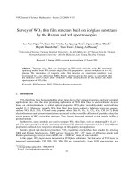
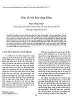
based on the XRD patterns in figure
1 and image of AFM in figure 2, we
conclude that the film has a small
amount of anatase crystal structure
with a threshold thickness of
360nm, and the best photo-catalytic
properties. This shows that the film
has an amorphous crystal structure
when the film thickness is smaller
than the threshold value, and its
effective surface area is small, so the
photo-catalytic properties were
degraded. When film thickness is
large than the threshold value
electrons and holes have no chance
reaching its surface before
recombining, since the diffusion length of the electron is smaller than the thickness of the film. In this
case, the effective area of the film surface decreases because some of its crystal grains enlarge, so the
photo-catalysis decreases. Thus, approaching the thickness threshold, films reduce the maximum
number of electrons and holes recombined before they diffuse to the surface. In addition, the thickness
threshold is large enough for the film to form an anatase crystal structure and achieve the largest
effective surface area.
Fig. 1. XRD spectrum versus thickness of TiO
2
.films.
Fig. 2. AFM image of TiO
2
samples.
Le Tran et al. / VNU Journal of Science, Mathematics - Physics 24 (2008) 231-237
234
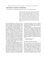
Fig. 3. Refractive index of TiO
2
films determined from
Swanapoel method.
3.2. Optical parameters of TiO
2
, TiN film
3.2.1 Defining the thickness and index of TiO
2
film
The UV-vis spectral transmission of TiO
2
films was measured by advanced technology
such as the V350 spectrophotometer at the
University of Natural Sciences, Ho Chi Minh
City. Based on spectral transmission, we
measure the thickness and refractive index of
the film by the Swanapoel method [11], then,
fit the film refractive index in accordance with
the Cauchy model wavelength, as shown in
Figure 3. The Swanapoel method is
programmed by Matlab.
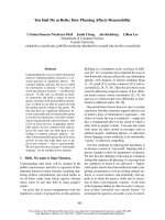
3.2.2 Defining the thickness of TiN film
The thickness, refractive index n, and
extinction coefficient k of TiN films is defined
by the Ellipsometry method Figure 4.
3.2.3. Theoretical spectral transmittance and
reflectance of multi-layer TiO
2
/TiN/TiO
2
films
Based on the results in Sections 3.2.1 and
3.2.2 we find the refractive index n,
extinction coefficient k of the outer TiO
2
layer, the TiN layer and the inner TiO
2
layer
at the 550nm wavelength, as shown in Table
2. Based on the results in Table 1, the
O.S.Heavens
[9] matrix is used to find a
suitable thickness of each layer sufficient to
enable multi-layer films to effectively
transmit at the 550nm wavelength, as shown
in Table 3. Then, we can simulate the
theoretical spectral transmittance and
reflectance of the multi-layer film at the
wavelengths shown in Figure 5
From the data in Figure 5, m3 and m4 films
have high reflective coefficients, wide
wavelengths including solar radiation, and
transmission exceeding 40% in the visible
spectrum. The best thickness of the TiN layer is
smaller than 35nm. This is too large to enable the
transmission of the film be smaller than 40%.
Both films have the thickness of the top TiO
2
layer, which is about 360nm, and match the application
of photo-catalysis, as mentioned. However, the m4 film yields a transmission 50% higher than the m3
film, even though there is interference in the spectral reflectance. Thus, the m4 film is the best the
364/26/257 thickness on glass.
Fig. 4. Refractive index n and extinction coefficient k of
TiN determined by Ellipsometry method.
Table 2. Refractive index of TiO
2
, TiN films
at 550 nm wavelength
film outer TiO
2
TiN inner TiO
2
n 2.3 1.13 2.5
k 0 2.18 0
Le Tran et al. / VNU Journal of Science, Mathematics - Physics 24 (2008) 231-237
235
Table 3. Thickness of layers in samples m
1
, m
2
, m
3
, m
4
Layer Outer TiO
2
Tin Inner TiO
2
T
ax
sample
368 22 38 58.49 m1
367 24 37 56.43 m2
365 35 34 43.21 m3
364 26 257 54.23 m4
Thickness (nm)
368 22 38 58.49 m1
3.2.4. Experimental spectral transmittance and reflectance of multi-layer TiO
2
/TiN/TiO
2
film
From the simulated result in
Section 3.2.3, we experimented with data
of the m3 and m4 films. The generated
film coincides quite well with the
simulated results of theory. This is shown
in Figure 6 and Figure 7. From the films
DL71 and DL85 from Figure 6 and
Figure 7 have the TiN layer which was
produced under the following conditions;
a threshold potential of 550 Volt, a
pressure of 3.10
-3
Torr, a ratio of
N
2
/Ar=10% as mentioned [10]. The outer
TiO
2
layer is fabricated at the optimum
sputtering intensity, which is about 0.45
Ampere, and a sputtering pressure of
13mTorr, to ensure that the
film has the
required photo-catalytic properties. The
Fig. 6. Theoretical and experiment
transmittance and reflectance spectra
of TiO
2
/TiN/TiO
2
films m3 and DL71.
Fig. 5. Theoretical transmittance and reflectance spectra
of the multi-layer films.
Fig. 7. Theoretical and experiment transmittance and
reflectance spectra of TiO
2
/TiN/TiO
2
films m4 and DL85.
Le Tran et al. / VNU Journal of Science, Mathematics - Physics 24 (2008) 231-237
236
inner TiO
2
layer is fabricated at an intensity of 0.5
Ampere and a pressure of 10
-3
Torr, to ensure that
the film has a high refractive index, and the surface
morphology of the film is smooth. This enables an
increase in the reflectance and a strong buffer layer.
Both TiO
2
layers are fabricated at a ratio of O
2
/Ar =
8%.
3.3. Examples of multi-layer films
The X-ray diffraction pattern and MB
decomposition of some multi-layer films are
described in Figure 8 and Table 4. It is clear that the
specimens discovered involve a highly iterative process in terms of
photo-catalytic capability, and regularity, as mentioned in Section
3.1. A (101) surface corresponding to the anatase phase, locates at
2θ = 24.6. At this position, the lower the diffractive peak of the
outer is, the better the photo-catalytic
capabilities of the films. The
outer TiO
2
layer was grown better on the TiN layer than on glass,
since glass is amorphous. Therefore, the multi-layer TiO
2
/TiN/TiO
2
films have better crystal structure than the single layer TiO
2
on the
glass substrate. This is confirmed by the appearance of the peak
A(004) surface of some multi-layer films.
4. Conclusion
We found that the thickness threshold is about 360 nm for the outer TiO
2
layer, which enables
the last exhibit best photo-catalytic and transmittance heating mirror properties; the theoretical matrix
problem of multi-layer film is formulated, then, computed using the experiment data for the refractive
index n, and the extinction coefficient k of each layer. The spectral reflectance and the transmittance
of the heat mirror TiO
2
/TiN/TiO
2
determined from the experiment, perfectly coincides with the
theoretical simulation, and the results can be replicated. The fabricated transmittance heat mirror films
TiO
2
/TiN/TiO
2
have both the transparent heat mirror property and the same photo-catalysis properties
as the single-layer films TiO
2
.
References
[1] H.K. Pulker, “Coating on Glass” ELSEVIER (1984) 423.
[2] Cheng-Chung Lee, “Optical Monitoring of Silver-based Transparent Heat Mirrors”, Applied Optics Vol.35, No.28,
(1996) 5698.
[3] R.J.martin-palma, “Accurate determine of the optical constants of sputter-deposited Ag and SnO
2
for low emissivity
coating”, J.Vac.Sci.Technol. A Vol. 16, No.2 (1998) 409.
[4] C.M. Lampert, Solar Energy Mater (1979) 319.
[5] J.C.C FAN, F.J.Bachner, ibid 15 (1976) 1012.
Fig. 8. XRD pattern of TiO
2
/TiN/TiO
2
films.
Table 4. MB decomposition of
TiO
2
/TiN/TiO
2
films
Sample
∆ABS
DL87 0.17
DL89 0.19
DL90 0.25
DL71 0.23
DL66 0.18
Le Tran et al. / VNU Journal of Science, Mathematics - Physics 24 (2008) 231-237
237
[6] D.C.Martin, R.Bell, “in Proceeding of Conference on Coatings for the Aerospace Environment”, Dayton, Ohio,
WADD-TR-60-TB, (1960).
[7] Akira Fujishima, Tata N. Rao, Donald A.Tryk, “Titanium dioxide photocatalysis”, Journal of Photochemistry and
Photobiology C: Photochemistry Reviews 1 (2000) 1.
[8] K. Eufinger, D. Poelman, H. Poelam, R. De Gryse, G.B. Marin “ Photocatalytic activity of dc magnetron sputter
eposited amorphous TiO
2
thin films” Applied surface science Vol. 254 (2007) 148.
[9] O. S. Heaven, “Optical Properties of Thin Solid Films”, London Butterworths Scientific Publication, ch.4, (1955).
[10] Min Jae Jung, Ho Young Lee, and Jeon G. Han Chung-k. Jung, Jong-S. Moon, and Jin-Hyo Boo “High-rate and low-
temperature synthesis of TiO
2
, TiN and TiO
2
/TiN/TiO
2
thin films and study of their optical and interfacial
characteristics” J. Vac. Sci. Technol. B 23(4) 2005.
[11] R.Swanepoel, “Dertermination Of The Thickness And Optical Constants Of Amorphous Silicono” , J. Phys. E: Sci
Instrum, Vol. 16, May (1983).