Synthesis of zeolite-templated carbons using oxygen-containing organic solvents
Bạn đang xem bản rút gọn của tài liệu. Xem và tải ngay bản đầy đủ của tài liệu tại đây (4.52 MB, 9 trang )
Microporous and Mesoporous Materials 318 (2021) 111038
Contents lists available at ScienceDirect
Microporous and Mesoporous Materials
journal homepage: />
Synthesis of zeolite-templated carbons using oxygen-containing
organic solvents
Hongjun Park a, Jisuk Bang a, b, Seung Won Han a, Raj Kumar Bera a, Kyoungsoo Kim c,
Ryong Ryoo a, b, *
a
b
c
Center for Nanomaterials and Chemical Reactions, Institute for Basic Science (IBS), Daejeon, 34141, Republic of Korea
Department of Chemistry, Korea Advanced Institute of Science and Technology (KAIST), Daejeon, 34141, Republic of Korea
Department of Chemistry, Jeonbuk National University, Jeollabuk-do, 54896, Republic of Korea
A R T I C L E I N F O
A B S T R A C T
Keywords:
Zeolite-templated carbon
Organic solvent
Synthesis
Chemical vapor deposition
Supercapacitor application
Zeolite-templated synthesis of ordered microporous carbons was performed with Ca2+ ion-exchanged Y and beta
zeolites, where the conventionally used carbon source gases (e.g., ethylene and propylene) were replaced by
various organic solvents, such as methanol, ethanol, isopropanol, acetone, tetrahydrofuran, and diisopropyl
ether. The oxygen-containing solvents were fed to the zeolites as carried by N2 gas through a bubbler. Mass
spectrometric analyses of the carbonization stream indicated that isopropanol, acetone, tetrahydrofuran, and
diisopropyl ether were converted largely to propylene and H2O vapor, while ethanol and methanol to ethylene.
The simultaneous generation of H2O and the olefins, without using high-pressure gas cylinders, can be merit in
the Ca2+ ion-catalyzed synthesis of zeolite-templated carbons (ZTCs). The approach in this work provides a facile
way to produce high quality ZTCs exhibiting excellent micropore orders and high specific capacitances in
supercapacitor applications.
1. Introduction
Three-dimensional (3D) graphenes refer to carbonaceous materials
with a 3D interconnected porous structure made up of a single layer of
sp2-bonded carbon atoms [1–3]. The 3D graphenes, particularly those
with a negative Gaussian curvature along the carbon surfaces, have
received considerable attention in recent years. Research groups have
proposed saddle-like, negatively curved structure having heptagonal or
octagonal carbon rings, which are expected to alter the electrical,
magnetic, optical, and mechanical properties as compared to those of 2D
graphenes [4–8]. Especially, due to their unique properties, synthesis of
negatively curved carbon materials that resemble triply periodic mini
mal surfaces (so-called Schwarzites) have been explored for a long time
[9,10]. Theoretical works suggested that the 7- or 8-membered rings
would cause stronger adsorption of Li ions and other adsorbates on the
carbon surfaces, thereby increasing the adsorption capacity [11–13].
Furthermore, it has been demonstrated that 3D graphene-based carbons
exhibit new and potentially useful catalytic properties in (de)hydroge
nation, rearrangement, and isomerization reactions [14,15].
Among various routes to produce nanoporous carbons [16,17], the
most effective way to generate 3D graphene-like surface structures is to
use zeolite templates [18–21]. The first step of the zeolite-templated
carbon (ZTC) synthesis is pyrolytic carbonization of a carbon source
(typically, acetylene, ethylene or propylene) in zeolite pores. The second
step is liberation of the deposited carbon framework by dissolution of
the template using HF/HCl or NaOH/HCl [22]. The carbon product has
an ordered microporous structure, corresponding to a negative replica of
the zeolite. There are more than 200 kinds of zeolite, but only a few of
them with pore apertures built with 12≡Si–O- units, such as FAU (X and
Y), EMT and beta zeolites, have practical significance as a ZTC template.
The 12-membered oxygen-ring (or 12 MR) pore apertures of these ze
olites are similar to the diameter of C60 fullerene, but too narrow for the
formation of any multi-walled carbon nanotubes. The only problem with
the 12 MR zeolites is that the tightly fitting pores tend to cause serious
diffusion limitations for the carbon sources [19,23]. Consequently, the
ZTC synthesis often suffers from incomplete filling of carbon in the in
ternal micropores of the template, and also deposition of graphite-like
carbon multilayers at the external surfaces [24–26].
Several approaches have been proposed to resolve the diffusion
limitation problem. A commonly employed method is to conduct a flow-
* Corresponding author. Center for Nanomaterials and Chemical Reactions, IBS, Daejeon, 34141, Republic of Korea.
E-mail address: (R. Ryoo).
/>Received 18 January 2021; Received in revised form 10 March 2021; Accepted 12 March 2021
Available online 17 March 2021
1387-1811/© 2021 The Authors.
Published by Elsevier Inc.
This is an open
( />
access
article
under
the
CC
BY-NC-ND
license
H. Park et al.
Microporous and Mesoporous Materials 318 (2021) 111038
type chemical vapor deposition (CVD) through a thin bed of zeolite
powder, using a hydrocarbon gas diluted in N2 or by low-pressure CVD
[26]. Agitation of zeolite bed using a rotary tubular furnace has also
been proposed for uniform infiltration of the carbon sources [23].
Whereas these approaches focused on optimizing physical parameters,
the laboratory of the present authors has developed a chemical method
that involves the incorporation of La3+, Y3+, or Ca2+ within the zeolite
template by an ion exchange process [19,27,28]. A common feature of
these metal cations is that they are carbide forming elements. These
carbide-forming cations promoted (or catalyzed) the CVD of ethylene,
but the catalytic function required feeding of H2O vapor.
In the present work, based on the Ca2+ ion-promoted ZTC synthesis,
we explored possibilities for using common laboratory organic solvents,
instead of ethylene stored in a high-pressure cylinder. Up to now, a few
carbon sources in liquid state have already been reported in ZTC syn
theses, such as acetonitrile, benzene, 2-methylfuran, methanol and
ethanol [20,24,29–32]. Each of these previous works was specialized to
a particular kind of organic compound in a Na+ or H+ ion-exchanged
zeolite. In the present work, we sought a more generalized principle
that would be useful for the selection of liquid carbon sources, through
ZTC synthesis tests with methanol, ethanol, isopropanol (IPA), acetone,
tetrahydrofuran (THF), and diisopropyl ether (DIPE) with Ca2+
ion-exchanged Y and β templates. These oxygen-containing compounds
were chosen since they were easily available, and furthermore, expected
to produce H2O vapor under the carbonization conditions.
adsorption at − 186.15 ◦ C, X-ray powder diffraction (XRD, Cu Kα radi
ation with λ = 0.154 nm), and transmission electron microscopy (TEM).
All the characterizations were performed following the same procedures
reported previously [22].
2. Experimental section
Decomposition products of the organic solvents were analyzed using
an on-line installed quadrupole mass spectrometer (Pfeiffer Vacuum).
The gas sampling was performed continuously from the outlet of the
CVD stream through a capillary sampler to the mass spectrometer. The
multichannel mass signal intensities were plotted as a function of CVD
time under various deposition conditions. These plots were used to
analyze chemical species that were generated during the CVD. The flow
rate and heating conditions were the same as described above, except
that the organic solvents were flowed as carried in He (99.999%,
Joongang gas) bubbles instead of N2, to avoid overlapping of N2 mass
peaks with those of ethylene.
2.4. Electrochemical capacitance measurements
For measuring capacitance in an aqueous electrolyte, a carbon ink
was prepared following the method in the literature [22]. In specific, 5
mg of ZTC was dispersed in a mixture of 0.084 mL of water, 0.1 mL of 5
wt% Nafion (Sigma-Aldrich), and 0.316 mL of ethanol by sonication for
1 h. The working electrode was prepared through drop casting 8 μL of
the ink on an alumina-polished glassy carbon electrode (d = 5 mm). The
mass-areal loading of the carbon in the electrode was 0.4 mg cm− 2. The
capacitance was measured in negative potential window of − 0.2–0.8 V
vs. Ag/AgCl with three-electrode system. A 1 M Na2SO4 aqueous solu
tion saturated with N2 gas was used as the electrolyte. Cyclic voltam
metry (CV) and Galvanostatic charge/discharge (GCD) measurements
were performed using a workstation (Autolab PGSTAT30) at room
temperature. The CV curve was obtained after repeated scans for sta
bilization. The specific capacitance was calculated from the GCD curve,
measured after CV stabilization, by following the equations in the
literature [34].
2.5. Mass analysis in carbonization stream
2.1. Zeolite preparation
FAU-Y zeolite with Si/Al = 2.4 was synthesized following the same
procedures reported previously [33]. Three samples of FAU zeolite and
one sample of beta zeolite were purchased in a powder form from Tosoh.
The Tosoh zeolite codes of these samples are HSZ-320NAA (Y with Si/Al
= 2.8), HSZ-350HUA (USY with Si/Al = 5.5), HSZ-360HUA (USY with
Si/Al = 7.5), and HSZ-HOA301 (β with Si/Al = 14), respectively. A
FAU-X zeolite (Si/Al = 1.2, 13X) was purchased from Sigma-Aldrich. All
the zeolite samples were ion-exchanged into a Ca2+ ionic form prior to
their use as a carbon template, following the ion-exchange procedure
reported elsewhere [28].
3. Results and discussion
3.1. Evaluation of carbon precursors for CaY-ZTC synthesis
2.2. Carbon synthesis
In the present ZTC synthesis, it was important to achieve the initial
deposition of carbonaceous polymers as fully as possible throughout the
entire zeolite micropore system, without the deposition at external
surfaces. To do this, the precursor concentration and the deposition
temperature were optimized for each carbon precursor with a lab-made,
Ca2+ ion-exchanged Y zeolite (denoted by CaY, Si/Al = 2.4, Ca/Al =
0.45). IPA, acetone, THF, DIPE, ethanol, and methanol were tested as
carbon precursors because of their high volatility near room tempera
ture. The test was performed with a N2-bubbled vapor stream without
additional feeding of water vapor, which is in contrast to the case of
ethylene precursor [19,28]. For each carbon precursor, the pyrolytic
deposition conditions were optimized through the exploration of the
effects of temperature and organic vapor pressure. The optimized syn
thesis conditions obtained in this manner are summarized in Table 1.
The ‘Carbon Products’ in Table 1 indicate the resultant carbon products
collected after liberation from the zeolite template using an aqueous
solution of HF/HCl mixture.
As shown in Table 1, when IPA was used as a carbon precursor in
CaY, the optimum time for the pyrolytic deposition was 4 h at 550 ◦ C.
The resultant ZTC yield from IPA was 0.30 g carbon per g CaY zeolite,
which was similar to the carbon yields from ethylene and propylene in
1
the same zeolite (0.33 g g−zeolite
). On the other hand, when NaY zeolite
was used as a template, the carbon yield from IPA was only 0.03 g
1
g−zeolite
. Even in the case of HY zeolite, the carbon yield was only 0.15 g
Isopropyl alcohol (99.5%, Sigma-Aldrich), acetone (99.9%, SigmaAldrich), tetrahydrofuran (99.5%, Daejung), diisopropyl ether (99.0%,
Sigma-Aldrich), ethanol (99.9%, Merck), and methanol (99.9%, Merck)
were used for carbon synthesis as purchased. These organic solvents
were fed as a vapor carried by N2 gas through a bubbler. Typically, 0.3 g
of a zeolite sample was placed on a fritted disk in a vertically mounted,
fused quartz reactor (d = 15 mm). The reactor was heated to a desired
temperature for carbonization under a high-purity N2 gas flow at a rate
of 60 cm3 min− 1. The N2 flow was then switched to flow through a N2
bubbler containing an organic solvent. The concentration of the organic
solvent in N2 was controlled by the temperature of a constanttemperature bath surrounding the bubbler. The flow of the organic
vapor was maintained in this manner over 2–5 h. The exact time of flow
was optimized, depending on the carbon source and the bubbler tem
perature. After the carbon deposition in zeolite pores was accomplished,
the zeolite-carbon composite was heated for 1 h at 900 ◦ C under a N2
flow. The resultant carbon was then released from the zeolite template
using a mixture of 1.0 M HF (J.T. Baker) and 1.0 M HCl (Junsei), as
reported elsewhere [28].
2.3. Materials characterization
Characterization of carbon samples was performed by argon
2
H. Park et al.
Microporous and Mesoporous Materials 318 (2021) 111038
Table 1
Optimized carbonization conditions and results for CaY zeolite and various carbon precursors.
Zeolite-Carbon
Source
Carbonization Conditions
Tb ( C)
N2/Organic Flow Rates (cm min
CaY-IPA
CaY-Acetone
CaY-THF
CaY-DIPE
CaY-Ethanol
CaY-Methanol
CaY-Propylene
CaY-Ethylene
20
− 10
3
3
20
− 5
30h
30h
60/3
60/3
60/3
60/3
60/3
60/3
60/15
60/15
a
c
d
e
f
g
h
a ◦
Carbon Products
b
3
− 1
)
Tcc (◦ C)
d
t (h)
1
Carbon Yielde (g g−zeolite
)
SBETf (m2 g− 1)
Vmicrog (cm3 g− 1)
550
550
550
550
600
600
550
600
4
2
2
3
3
2
4
3
0.30
0.31
0.31
0.30
TABLE
0.34
0.31
0.33
3600
3740
3370
3780
2780
2720
3520
2710
1.43
1.48
1.33
1.49
1.20
1.07
1.39
1.09
Bubbler temperature.b Flow rate was determined by solvent vapor pressure at corresponding bubbler temperature.
Carbonization temperature.
Carbonization time.
Carbon yield was determined by TGA.
BET specific surface area was calculated from the adsorption data in the relative pressure (P/P0) region between 0.05 and 0.15.
Micropore volume was determined from the density functional theory cumulative volume in the pore size range of D < 2 nm.
Temperature of bubbler used to feed water vapor.
1
g−zeolite
. This result indicates that Ca2+ ions in the zeolite acted as an
effective catalyst or promotor for the IPA carbonization process, as
compared to Na+ and H+. The resultant IPA-derived ZTC product from
CaY exhibited a high Brunauer–Emmett–Teller (BET) surface area of
3600 m2 g− 1 with a large micropore volume of 1.43 cm3 g− 1. Similar to
the case of IPA, when acetone, THF, and DIPE were used as the carbon
sources, the carbon deposition in CaY was accomplished at 550 ◦ C
(Table 1). The obtained ZTC products exhibited excellent BET surface
areas (3370–3780 m2 g− 1) with large micropore volumes (1.33–1.49
cm3 g− 1), which were comparable to those of the IPA-based carbon.
However, when methanol and ethanol were used as the carbon pre
cursors, the optimum temperature for the carbonization had to be
increased to 600 ◦ C. The carbon yields from methanol and ethanol were
similar to those from IPA, acetone, THF, and DIPE, but there was a
significant difference in the porous textural properties. That is, the BET
surface areas (~2700 m2 g− 1) and micropore volumes (~1.1 cm3 g− 1) of
the ZTCs from both ethanol and methanol were 20–30% lower,
compared with the other four organic solvents.
Based on the required carbonization temperature and the resultant
BET areas and pore volumes, the carbon precursors could be classified
into two groups, represented as IPA-group compounds (i.e., IPA,
acetone, THF and DIPE) and ethanol-group compounds (i.e., ethanol and
methanol). The BET surface areas and micropore volumes of the ZTCs
from the IPA-group compounds were similarly high to those of the
carbon from propylene (3520 m2 g− 1, 1.39 cm3 g− 1). On the other hand,
the ethanol-group compounds yielded ZTC products having specific
surface areas and pore volumes much alike to those of carbon from
ethylene (2710 m2 g− 1, 1.09 cm3 g− 1), which were comparatively low.
Further details of the carbon characterization resulting from the six
solvents are discussed in the following section.
deposition of graphite-like multilayer carbons on the external surfaces.
However, the internal ZTC frameworks showed detectable differences in
the long-range pore order, consistent with the quality trend of IPA ≈
acetone ≈ THF ≈ DIPE ≈ propylene ≫ ethanol ≈ methanol ≈ ethylene.
As shown in Fig. 1b and c, both the ZTCs from IPA and ethanol exhibited
lattice fringes with a d-spacing of 1.4 nm, but there was a noticeable
difference in the long-range orders (see TEM images in Fig. S1 for the
other samples).
We investigated the chemical bonding nature of the ZTC products,
using 13C MAS NMR and Raman spectroscopy. The 13C NMR spectra of
the carbon samples showed a single broad peak centered at 120–130
ppm, which is characteristic of sp2-hybridized carbons, regardless of the
choice of the carbon precursors (Fig. S2) [19,36,37]. The similarity in
their chemical structures was again observed in the Raman spectra,
which exhibited the formation of a single-layered carbon framework
along the zeolite surface. These results are similar to our previous work
on ethylene carbonization (Fig. S3) [28,38,39]. The C/H/O elemental
ratios of the ZTCs (i.e., 93/2/5 in weight ratio or simply C25H6⋅4O) were
also very similar to each other (Table S1). In addition, the IPA-derived
ZTC sample exhibited very similar thermal stability to that of ZTCs
resulting from ethylene and propylene upon calcination in air (Fig. S4)
[19].
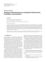
The ZTC products in Table 1 were further examined by micropore
analyses using Ar adsorption (Fig. 2). The results showed a very sharp
increase of adsorption quantity in the region of P/P0 < 0.02, at which
indicates that the carbons were highly microporous with an extremely
narrow distribution of micropore diameters. All four ZTC samples ob
tained from IPA group possessed about a 20–35% higher volume of
micropores than the volumes of ZTCs synthesized with ethanol group. In
addition, the former group of ZTCs exhibited a sharper distribution of
micropore diameters. The narrow distribution peak centered at ~0.9 nm
in Fig. 2 insets can be interpreted as a result of faithful replication of the
zeolite micropores into the ZTC frameworks [19,40]. From the results, it
was suggested that the micropores in the carbons from IPA, acetone,
THF, and DIPE were more faithfully replicated than the cases of ethanol
and methanol.
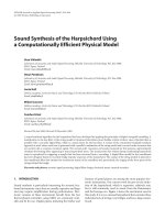
The ZTC products in Table 1 were further examined to check whether
the surface area variation would actually cause a significant difference
in specific capacitance. Fig. 3 shows the capacitance values measured in
an aqueous solution of Na2SO4 (see Fig. S5 for CV curves and Fig. S6 for
GCD profiles). The capacitance values show a good linear correlation
with the BET surface areas. This result is in good agreement with pre
vious works supporting that the supercapacitor capacitance should be
proportional to the specific surface areas when compared with carbons
with similar surface chemistry under a sufficiently low discharge rate
[41–44]. Under these conditions, the effects of the electrical resistance
3.2. Pore structure of CaY-templated carbon products
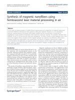
Fig. 1a shows the powder XRD patterns of the ZTC products shown in
Table 1. All the XRD patterns have a sharp XRD peak centered at 2θ =
6.5◦ (i.e., d = 1.4 nm). The presence of the XRD peak indicates that the
ordered microporous structure of the zeolite has been inherited to the
carbons successfully [19,35]. However, there is a remarkable difference
in the peak intensity between the ZTCs obtained from the
IPA-acetone-THF-DIPE-propylene group and those from the
ethanol-methanol-ethylene group (Fig. 1a). The difference is in good
agreement with the aforementioned analysis of surface areas and
micropore volumes. Based on this analysis, we believe that the quality of
the ZTCs varies in the order of IPA ≈ acetone ≈ THF ≈ DIPE ≈ pro
pylene ≫ ethanol ≈ methanol ≈ ethylene. We investigated TEM images
of all the ZTC products. The TEM image analysis indicated no significant
3
H. Park et al.
Microporous and Mesoporous Materials 318 (2021) 111038
Fig. 1. (a) Powder XRD patterns of the CaY-ZTC samples synthesized using different precursors under the synthesis conditions summarized in Table 1. Each XRD
pattern was obtained under the same measurement conditions. The intensity in the XRD patterns was expressed in the same unit (i.e., counts per second, cps).
Representative TEM images of the carbons from (b) IPA and (c) ethanol.
could be neglected, and the specific capacitance would be decided by the
surface areas available for the electrolyte adsorption [45,46]. Based on
the present capacitance results, we believe that all the measured BET
surface areas of the ZTCs could be equally utilized for the adsorption of
electrolyte ions.
The aperture diameter (0.67 nm in β) is similar to that of FAU-Y zeolite
(0.74 nm) [47], but they have markedly different pore shapes (see
Fig. S7 for structure models). β zeolite is a typical channel-type zeolite,
with micropores perpendicularly interconnected to form a 3D porous
network [48]. The β zeolite template was ion-exchanged three times
with Ca2+.
In the case of the Ca2+ ion-exchanged β (Caβ) zeolite with Si/Al = 14,
the precursor trend was completely reversed. As shown in Table 2, the
BET area and pore volume of the resultant Caβ-ZTCs decreased in the
order of ethanol ≈ methanol ≈ ethylene (3400 m2 g− 1, 1.36 cm3 g− 1) ≫
IPA ≈ acetone ≈ THF ≈ DIPE ≈ propylene (2350 m2 g− 1, 0.93 cm3 g− 1),
as shown in Table 2. This order was consistent with the XRD data
(Fig. S8). As shown in Fig. 4a, the XRD pattern of the ethanol-derived
3.3. Evaluation of carbon precursors for Caβ-ZTC synthesis
In the case of CaY-templated carbons, the IPA group precursors gave
distinctively high-quality ZTC products, compared to those synthesized
with the ethanol group precursors. However, this result was only a
particular case for CaY zeolite. The ZTC synthesis was investigated with
a β zeolite with Si/Al = 14. The β zeolite also has 12 MR pore apertures.
4
H. Park et al.
Microporous and Mesoporous Materials 318 (2021) 111038
Fig. 2. Ar adsorption-desorption isotherms of the CaY-ZTC samples synthesized using the organic precursors (solid line), which were compared to the isotherm of the
carbon synthesized using ethylene (dashed line). Insets of each graph are the pore size distributions of the carbon products synthesized using each organic precursor.
The horizontal axis of the inset plots is pore diameter (D, nm), and the vertical axis is dV/dD (cm3 g− 1 nm− 1).
ZTC product from Caβ zeolite exhibited broad but well-distinguished
The CVD conditions for β zeolite were also individually optimized for
each carbon source, in the same manner as described in the synthesis of
FAU-ZTC in the previous section. The optimized synthesis results are
presented in Fig. 4 and Table 2.
Bragg reflections at 2θ = 7.8◦ and 15◦ , indicating replication of the
(101) and (201) planes in the polymorph A of beta zeolite (BEA*) [31,
49–51]. The structural order of the Caβ-ZTC from ethanol was similar to
that of the ethylene-based Caβ-ZTC. However, in the cases of IPA and
propylene, both ZTC products exhibited only a low-intensity peak at
7.8◦ . The Ar adsorption analysis was consistent with the XRD data
(Fig. 4b and 4c). The TEM image of all the Caβ-ZTC samples (Fig. S9)
showed that the carbon had lattice fringes of 1.1 nm. The lattice fringes
in β-ZTC looked somewhat disordered. This did not originate from poor
template replication, but rather from the intrinsic structural disorder of
three polymorph structures in β zeolite itself [48]. Among the Caβ-ZTCs,
the carbons obtained from ethanol-based precursors exhibited an even
sharper distribution of micropore diameters than those from the
IPA-group precursors. As these results show, these ZTC products
exhibited a very sharp peak at D ≈ 1 nm, which is ascribed to the
5
H. Park et al.
Microporous and Mesoporous Materials 318 (2021) 111038
ion-exchanged templates, H2O vapor was reported to be essential to
promote pore-selective carbon deposition by activating the metal ion
catalyst [16,28]. In the case of the organic solvent precursor, no addi
tional feeding of water vapor was needed, which is convenient in terms
of the experimental apparatus. All the IPA-group compounds were
decomposed to produce propylene as a major acting carbon source
rather than ethylene. On the other hand, in the case of the ethanol-group
compounds, ethylene was a major decomposition product. The product
difference clarified why the IPA-group compounds exhibited carbon
deposition behavior similar to that of propylene, while ethanol and
methanol behaved similar to ethylene.
To understand the difference in the carbonization characteristics of
ethylene and propylene within Y and β zeolites, we reinvestigated the
effect of zeolite Si/Al ratios on the structural quality of the carbon
products from propylene and ethylene [20,54,55]. Fig. S11 shows XRD
patterns of the ZTC products that were synthesized using X zeolite
(Si/Al = 1.2), Y zeolite (Si/Al = 2.4), and two USY zeolite (Si/Al = 5.5
and 7.5, respectively) templates. The four zeolites have the same FAU
structure, except for the differences in the Si/Al ratio and corresponding
changes in the lattice parameter [56]. The XRD patterns indicate that the
structural order of the ZTC products depended not only on the zeolite
Si/Al ratios but also on the carbon sources. When propylene was the
carbon precursor (Fig. S11a), the zeolites with both Si/Al = 1.2 and 2.4
gave ZTC products exhibiting a very sharp XRD peak centered at 2θ =
6.5◦ . However, the zeolites with Si/Al = 5.5 and 7.5 yielded ZTC
products exhibiting much lower structural orders. The higher the Al
content in the series of FAU zeolite templates was, the more highly or
dered were the carbon structures. In particular, the USY zeolite with
Si/Al = 7.5 provided a carbon product almost without structural order,
1
and the carbon yield was only 0.13 g g−zeolite
. In this zeolite, Ca2+ ions
appeared to exist too sparsely to form interconnected carbon frame
works. When ethylene was the carbon source in the FAU template, the
carbon deposition yield in the USY zeolite with Si/Al = 7.5 was
1
increased to 0.27 g g−zeolite
, but the resultant carbon product still
exhibited a very poor structural order (Fig. S11b). The other FAU zeo
lites with Si/Al = 1.2, 2.4, and 5.5 all yielded ZTC products exhibiting an
ordered microporous structure. One notable point in the ethylene-based
synthesis is that the ZTC structural order decreased as the zeolite Al
content increased within the series of FAU templates with Si/Al = 1.2,
2.4, and 5.5, while the trend was the opposite in the case of propylene.
According to these results, when choosing an appropriate precursor for
Ca2+-assisted ZTC synthesis, it would be helpful to consider the Si/Al
ratio of the zeolite template. This consideration for zeolite template will
be useful for adsorption, catalysis, and electrochemical applications of
the synthesized nanoporous carbon materials [57–61].
Fig. 3. Specific capacitance of CaY-ZTC electrodes (with dashed line as a guide
to the eye) measured in an aqueous 1 M Na2SO4 electrolyte at discharge current
density of 0.1 A g− 1 as a function of the BET surface area of the carbons. The
ZTC samples synthesized using (a) DIPE, (b) acetone, (c) IPA, (d) propylene, (e)
THF, (f) ethanol, (g) methanol, and (h) ethylene as the carbon source.
zeolite-inherited primary micropores. The shoulder peaks appearing at
around 1.5 nm (i.e., secondary micropores due to defective templating
[19]) were low in intensity, similar to the case of CaY-ZTCs from the
IPA-group precursors in Fig. 2. Based on these product characterization
results, we could conclude that the ethanol-group compounds were
more suitable as a carbon precursor for ZTCs than the IPA-group com
pounds when Caβ zeolite was the template.
3.4. Mechanistic investigation of ZTC synthesis
For better understanding of the different trends in carbonization
behavior of different solvent precursors, we investigated how the com
pounds are utilized as the carbon source, by analyzing the vapor stream
outflowing from the CaY-loaded carbonization reactor, using an on-line
mass spectrometer. The reactor temperature was set to 550 ◦ C or 600 ◦ C,
according to the carbonization temperatures given in Table 1. The mass
spectrum of the outflowing gas was continuously monitored until the
carbon deposition was completed after 4 h. Fig. 5 shows the mass spectra
taken in an early stage of the carbon deposition, where the zeolite color
changed to gray-black, but the deposited amount was still less than 0.03
1
g g−zeolite
. In this early stage, the mass spectra obtained from all six
organic compounds were decomposed into H2O (mass-to-charge ratio,
m/z = 18) and olefins, including ethylene (m/z = 28) and propylene (m/
z = 39 and 41). The organic decomposition into olefins occurred cata
lytically by the zeolite, except for IPA and ethanol [31,52,53], as
confirmed by the mass spectral analysis of the solvent stream passed
through an empty reactor at the same temperature (Fig. S10). It is
notable that in situ generation of H2O was observed for all six solvent
compounds used in this study. In the ZTC synthesis employing Ca2+
4. Conclusions
We report a facile synthesis of ZTCs using common organic solvents,
IPA, acetone, THF, DIPE, ethanol, and methanol, as a carbon source.
Under the present synthesis conditions, all the organic solvents were
decomposed into H2O and hydrocarbons (mainly ethylene and propyl
ene). The IPA and ethanol solvents were thermally decomposed before
Table 2
Optimized carbonization conditions and results for Caβ zeolite and various carbon precursors.
Zeolite-Carbon
Source
Carbonization Conditions
Tb (◦ C)
N2/Organic Flow Rates (cm3 min− 1)
Tc (◦ C)
t (h)
Carbon Products
1
Carbon Yield (g g−zeolite
)
SBET (m2 g− 1)
VMicro (cm3 g− 1)
Caβ-IPA
Caβ-Acetone
Caβ-THF
Caβ-DIPE
Caβ-Ethanol
Caβ-Methanol
Caβ-Propylene
Caβ-Ethylene
20
− 10
3
3
20
− 5
30
30
60/3
60/3
60/3
60/3
60/3
60/3
60/15
60/15
650
650
650
650
650
700
700
650
13
2
2
2
3
13
8
4
0.28
0.29
0.30
0.29
0.31
0.32
0.30
0.33
2350
2030
2160
2330
3220
2910
2730
3400
0.93
0.76
0.84
0.88
1.29
1.12
1.09
1.36
6
H. Park et al.
Microporous and Mesoporous Materials 318 (2021) 111038
Fig. 4. (a) XRD patterns of the carbon samples synthesized with Caβ zeolite, using IPA, ethanol, propylene, and ethylene under the synthesis conditions in Table 2. Ar
adsorption-desorption isotherms and the QSDFT pore size distributions (insets) of the carbons obtained with (b) IPA and (c) ethanol.
Fig. 5. Mass spectra of the solvent vapor including (a) IPA, (b) acetone, (c) THF, (d) DIPE, (e) ethanol and (f) methanol passing through CaY zeolite at 550 ◦ C. The
green dashed line (m/z = 18) corresponds to H2O, the red dashed line (m/z = 28) represents ethylene, and the blue dashed lines (m/z = 39 and 41) correspond to
+
C3H+
3 and C3H5 , respectively.
7
Microporous and Mesoporous Materials 318 (2021) 111038
H. Park et al.
reaching the zeolite in the reactor. The other solvents were catalytically
decomposed upon contact with the Ca2+ ion-embedded zeolite template.
Regardless of whether the decomposition occurred thermally or cata
lytically inside the zeolite, all the resultant carbon products exhibited
well-ordered microporous structures. However, the porous textural
properties (e.g., specific surface area and micropore-size distribution)
were remarkably different depending on the organic decomposition
products. In the case of the CaY template, the carbon precursors that
decompose mainly to propylene (e.g., IPA, acetone, THF, and DIPE) were
superior to those decomposing mainly to ethylene (e.g., ethanol and
methanol). This finding is consistent with the result showing that pro
pylene was a preferable carbon source over ethylene for ZTC synthesis
using low-silica zeolites, such as X and Y zeolites. In contrast, ethyleneproducing solvents were better suited for ZTC synthesis using β and USY
zeolites with high silica content, which was analogous to the result
showing that the pore structural order was better for ethylene than for
propylene. Based on the synthesis results from these diversified carbon
sources, we believe that ZTCs can be obtained with a variety of
elemental compositions and chemical functionalities toward practical
applications.
[9] A. Mackay, H. Terrones, Diamond from graphite, Nature 352 (6338) (1991) 762,
762.
[10] E. Braun, Y. Lee, S.M. Moosavi, S. Barthel, R. Mercado, I.A. Baburin, D.
M. Proserpio, B. Smit, Generating carbon schwarzites via zeolite-templating, Proc.
Natl. Acad. Sci. U. S. A 115 (35) (2018) E8116–E8124, />pnas.1805062115.
[11] S. Park, K. Kittimanapun, J.S. Ahn, Y.-K. Kwon, D. Tom´
anek, Designing rigid
carbon foams, J. Phys. Condens. Matter 22 (33) (2010) 334220, />10.1088/0953-8984/22/33/334220.
[12] D. Odkhuu, D.H. Jung, H. Lee, S.S. Han, S.-H. Choi, R.S. Ruoff, N. Park, Negatively
curved carbon as the anode for lithium ion batteries, Carbon 66 (2014) 39–47,
/>[13] D.D. Borges, D.S. Galvao, Schwarzites for natural gas storage: a grand-canonical
Monte Carlo study, MRS Adv 3 (1) (2018) 115–120, />adv.2018.190.
[14] H.C. Kwon, S. Yook, S. Choi, M. Choi, Comprehensive understanding of the effects
of carbon nanostructures on redox catalytic properties and stability in oxidative
dehydrogenation, ACS Catal. 7 (8) (2017) 5257–5267, />acscatal.7b01742.
[15] P. Sazama, J. Pastvova, C. Rizescu, A. Tirsoaga, V.I. Parvulescu, H. Garcia,
L. Kobera, J.r. Seidel, J. Rathousky, P. Klein, Catalytic properties of 3D graphenelike microporous carbons synthesized in a zeolite template, ACS Catal. 8 (3) (2018)
1779–1789, />[16] V. Malgras, J. Tang, J. Wang, J. Kim, N.L. Torad, S. Dutta, K. Ariga, M. Hossain,
A. Shahriar, Y. Yamauchi, Fabrication of nanoporous carbon materials with hardand soft-templating approaches: a review, J. Nanosci. Nanotechnol. 19 (7) (2019)
3673–3685, />[17] W. Tian, H. Zhang, X. Duan, H. Sun, G. Shao, S. Wang, Porous carbons: structureoriented design and versatile applications, Adv. Funt. Mater. 30 (17) (2020)
1909265, />[18] T. Kyotani, T. Nagai, S. Inoue, A. Tomita, formation of new type of porous carbon
by carbonization in zeolite nanochannels, Chem. Mater. 9 (2) (1997) 609–615,
/>[19] K. Kim, T. Lee, Y. Kwon, Y. Seo, J. Song, J.K. Park, H. Lee, J.Y. Park, H. Ihee, S.
J. Cho, Lanthanum-catalysed synthesis of microporous 3D graphene-like carbons in
a zeolite template, Nature 535 (7610) (2016) 131–135, />nature18284.
[20] H. Nishihara, T. Kyotani, Zeolite-templated carbons–three-dimensional
microporous graphene frameworks, Chem. Commun. 54 (45) (2018) 5648–5673,
/>[21] J. Miao, Z. Lang, T. Xue, Y. Li, Y. Li, J. Cheng, H. Zhang, Z. Tang, Revival of zeolitetemplated nanocarbon materials: recent advances in energy storage and
conversion, Adv. Sci. 7 (20) (2020) 2001335, />advs.202001335.
[22] H. Park, S.K. Terhorst, R.K. Bera, R. Ryoo, Template dissolution with NaOH–HCl in
the synthesis of zeolite-templated carbons: effects on oxygen functionalization and
electrical energy storage characteristics, Carbon 155 (2019) 570–579, https://doi.
org/10.1016/j.carbon.2019.09.020.
[23] S. Choi, H. Kim, S. Lee, Y. Wang, C. Ercan, R. Othman, M. Choi, Large-scale
synthesis of high-quality zeolite-templated carbons without depositing external
carbon layers, Chem. Eng. J. 280 (2015) 597–605, />cej.2015.06.055.
[24] Y. Xia, R. Mokaya, D.M. Grant, G.S. Walker, A simplified synthesis of N-doped
zeolite-templated carbons, the control of the level of zeolite-like ordering and its
effect on hydrogen storage properties, Carbon 49 (3) (2011) 844–853, https://doi.
org/10.1016/j.carbon.2010.10.028.
[25] N.P. Stadie, M. Murialdo, C.C. Ahn, B. Fultz, Anomalous isosteric enthalpy of
adsorption of methane on zeolite-templated carbon, J. Am. Chem. Soc. 135 (3)
(2013) 990–993, />[26] K. Nueangnoraj, H. Nishihara, K. Imai, H. Itoi, T. Ishii, M. Kiguchi, Y. Sato,
M. Terauchi, T. Kyotani, Formation of crosslinked-fullerene-like framework as
negative replica of zeolite Y, Carbon 62 (2013) 455–464, />j.carbon.2013.06.033.
[27] S.H. Ko, T. Lee, H. Park, D.-S. Ahn, K. Kim, Y. Kwon, S.J. Cho, R. Ryoo, Nanocageconfined synthesis of fluorescent polycyclic aromatic hydrocarbons in zeolite,
J. Am. Chem. Soc. 140 (23) (2018) 7101–7107, />jacs.8b00900.
[28] K. Kim, Y. Kwon, T. Lee, S.J. Cho, R. Ryoo, Facile large-scale synthesis of threedimensional graphene-like ordered microporous carbon via ethylene carbonization
in CaX zeolite template, Carbon 118 (2017) 517–523, />carbon.2017.03.082.
[29] F. Su, J. Zeng, Y. Yu, L. Lv, J.Y. Lee, X. Zhao, Template synthesis of microporous
carbon for direct methanol fuel cell application, Carbon 43 (11) (2005)
2366–2373, />[30] Z. Yang, Y. Xia, X. Sun, R. Mokaya, Preparation and hydrogen storage properties of
zeolite-templated carbon materials nanocast via chemical vapor deposition: effect
of the zeolite template and nitrogen doping, J. Phys. Chem. B 110 (37) (2006)
18424–18431, />[31] K. Kim, M. Choi, R. Ryoo, Ethanol-based synthesis of hierarchically porous carbon
using nanocrystalline beta zeolite template for high-rate electrical double layer
capacitor, Carbon 60 (2013) 175–185, />carbon.2013.04.011.
[32] J. Wang, Z. Liu, X. Dong, C.-E. Hsiung, Y. Zhu, L. Liu, Y. Han, Microporous cokes
formed in zeolite catalysts enable efficient solar evaporation, J. Mater. Chem. 5
(15) (2017) 6860–6865, />
CRediT authorship contribution statement
Hongjun Park: Investigation, Data curation, Validation, Writing –
original draft. Jisuk Bang: Methodology, Investigation, Data curation.
Seung Won Han: Writing – review & editing. Raj Kumar Bera: Inves
tigation, Writing – review & editing. Kyoungsoo Kim: Methodology,
Supervision. Ryong Ryoo: Writing – review & editing, Project admin
istration, Supervision, Conceptualization, Visualization, Funding
acquisition.
Declaration of competing interest
The authors declare that they have no known competing financial
interests or personal relationships that could have appeared to influence
the work reported in this paper.
Acknowledgment
The work was supported by IBS-R004-D1.
Appendix A. Supplementary data
Supplementary data to this article can be found online at https://doi.
org/10.1016/j.micromeso.2021.111038.
References
[1] Z. Chen, W. Ren, L. Gao, B. Liu, S. Pei, H.-M. Cheng, Three-dimensional flexible and
conductive interconnected graphene networks grown by chemical vapour
deposition, Nat. Mater. 10 (2011) 424–428, />[2] C. Li, G. Shi, Three-dimensional graphene architectures, Nanoscale 4 (2012)
5549–5563, />[3] X. Cao, Z. Yin, H. Zhang, Three-dimensional graphene materials: preparation,
structures and application in supercapacitors, Energy Environ. Sci. 7 (2014)
1850–1865, />[4] M.-Z. Huang, W. Ching, T. Lenosky, Electronic properties of negative-curvature
periodic graphitic carbon surfaces, Phys. Rev. B 47 (3) (1993) 1593, https://doi.
org/10.1103/PhysRevB.47.1593.
[5] H. Terrones, M. Terrones, Curved nanostructured materials, New J. Phys. 5 (2003)
126, />[6] N. Park, M. Yoon, S. Berber, J. Ihm, E. Osawa, D. Tom´
anek, Magnetism in allcarbon nanostructures with negative Gaussian curvature, Phys. Rev. Lett. 91 (23)
(2003) 237204, />[7] A. Lherbier, H. Terrones, J.-C. Charlier, Three-dimensional massless Dirac fermions
in carbon schwarzites, Phys. Rev. B 90 (12) (2014) 125434, />10.1103/PhysRevB.90.125434.
[8] L.C. Felix, C.F. Woellner, D.S. Galvao, Mechanical and energy-absorption
properties of schwarzites, Carbon 157 (2020) 670–680, />carbon.2019.10.066.
8
H. Park et al.
Microporous and Mesoporous Materials 318 (2021) 111038
[33] D.W. Breck, Zeolite Molecular Sieves: Structure, Chemistry, and Use, John Wiley &
Sons, New York, London, Sydney, and Toronto, 1974.
[34] H. Lu, K. Kim, Y. Kwon, X. Sun, R. Ryoo, X. Zhao, Zeolite-templated nanoporous
carbon for high-performance supercapacitors, J. Mater. Chem. 6 (22) (2018)
10388–10394, />[35] Z. Ma, T. Kyotani, A. Tomita, Preparation of a high surface area microporous
carbon having the structural regularity of Y zeolite, Chem. Commun. (23) (2000)
2365–2366, />[36] Z. Ma, T. Kyotani, Z. Liu, O. Terasaki, A. Tomita, Very high surface area
microporous carbon with a three-dimensional nano-array structure: synthesis and
its molecular structure, Chem. Mater. 13 (12) (2001) 4413–4415, />10.1021/cm010730l.
[37] A.M. Panich, V.Y. Osipov, H. Nishihara, T. Kyotani, Nuclear magnetic resonance
study of zeolite-templated carbon, Synth. Met. 221 (2016) 149–152, https://doi.
org/10.1016/j.synthmet.2016.08.021.
[38] H. Nishihara, Q.-H. Yang, P.-X. Hou, M. Unno, S. Yamauchi, R. Saito, J.I. Paredes,
A. Martínez-Alonso, J.M. Tasc´
on, Y. Sato, A possible buckybowl-like structure of
zeolite templated carbon, Carbon 47 (5) (2009) 1220–1230, />10.1016/j.carbon.2008.12.040.
[39] H. Nishihara, H. Fujimoto, H. Itoi, K. Nomura, H. Tanaka, M.T. Miyahara, P.
A. Bonnaud, R. Miura, A. Suzuki, N. Miyamoto, Graphene-based ordered
framework with a diverse range of carbon polygons formed in zeolite
nanochannels, Carbon 129 (2018) 854–862, />carbon.2017.12.055.
[40] J. Parmentier, F.O. Gaslain, O. Ersen, T.A. Centeno, L.A. Solovyov, Structure and
sorption properties of a zeolite-templated carbon with the EMT structure type,
Langmuir 30 (1) (2014) 297–307, />[41] H. Shi, Activated carbons and double layer capacitance, Electrochim. Acta 41 (10)
(1996) 1633–1639, />[42] T.-C. Weng, H. Teng, Characterization of high porosity carbon electrodes derived
from mesophase pitch for electric double-layer capacitors, J. Electrochem. Soc. 148
(4) (2001) A368, />[43] E. Raymundo-Pinero, K. Kierzek, J. Machnikowski, F. B´eguin, Relationship
between the nanoporous texture of activated carbons and their capacitance
properties in different electrolytes, Carbon 44 (12) (2006) 2498–2507, https://doi.
org/10.1016/j.carbon.2006.05.022.
[44] L. Zhang, X. Yang, F. Zhang, G. Long, T. Zhang, K. Leng, Y. Zhang, Y. Huang, Y. Ma,
M. Zhang, Controlling the effective surface area and pore size distribution of sp2
carbon materials and their impact on the capacitance performance of these
materials, J. Am. Chem. Soc. 135 (15) (2013) 5921–5929, />10.1021/ja402552h.
[45] A.G. Pandolfo, A.F. Hollenkamp, Carbon properties and their role in
supercapacitors, J. Power Sources 157 (1) (2006) 11–27, />j.jpowsour.2006.02.065.
[46] H. Nishihara, H. Itoi, T. Kogure, P.X. Hou, H. Touhara, F. Okino, T. Kyotani,
Investigation of the ion storage/transfer behavior in an electrical double-layer
capacitor by using ordered microporous carbons as model materials, Chem. Eur J.
15 (21) (2009) 5355–5363, />[47] C. Baerlocher, L.B. McCusker, D.H. Olson, Atlas of Zeolite Framework Types,
Elsevier, 2007.
[48] J. Newsam, M.M. Treacy, W. Koetsier, C.d. Gruyter, Structural characterization of
zeolite beta, Roy. Soc. A. Math. Phy. 420 (1988) 375–405, />10.1098/rspa.1988.0131, 1859.
[49] T. Kyotani, Z. Ma, A. Tomita, Template synthesis of novel porous carbons using
various types of zeolites, Carbon 41 (7) (2003) 1451–1459, />10.1016/S0008-6223(03)00090-3.
[50] Z. Yang, Y. Xia, R. Mokaya, Enhanced hydrogen storage capacity of high surface
area zeolite-like carbon materials, J. Am. Chem. Soc. 129 (6) (2007) 1673–1679,
/>[51] C.M. Ghimbeu, K. Gu´
erin, M. Dubois, S. Hajjar-Garreau, C. Vix-Guterl, Insights on
the reactivity of ordered porous carbons exposed to different fluorinating agents
and conditions, Carbon 84 (2015) 567–583, />carbon.2014.12.034.
[52] A.B. Trenwith, Thermal decomposition of isopropanol, J. Chem. Soc., Faraday
Trans. 1 71 (1975) 2405–2412, />[53] J. Li, A. Kazakov, F.L. Dryer, Experimental and numerical studies of ethanol
decomposition reactions, J. Phys. Chem. 108 (38) (2004) 7671–7680, https://doi.
org/10.1021/jp0480302.
[54] N. Alam, R. Mokaya, The effect of Al content of zeolite template on the properties
and hydrogen storage capacity of zeolite templated carbons, Microporous
Mesoporous Mater. 144 (1–3) (2011) 140–147, />micromeso.2011.04.001.
[55] T. Aumond, J. Rousseau, Y. Pouilloux, L. Pinard, A. Sachse, Synthesis of
hierarchical zeolite templated carbons, Carbon Trends 2 (2020) 100014, https://
doi.org/10.1016/j.cartre.2020.100014.
[56] E. Dempsey, G. Kühl, D.H. Olson, Variation of the lattice parameter with aluminum
content in synthetic sodium faujasites. Evidence for ordering of the framework
ions, J. Phys. Chem. 73 (2) (1969) 387–390, />j100722a020.
[57] S. Lee, H. Park, J.W. Yoon, K. Kim, S.J. Cho, G. Maurin, R. Ryoo, J.-S. Chang,
Microporous 3D graphene-like zeolite-templated carbons for preferential
adsorption of ethane, ACS Appl. Mater. Interfaces 12 (2020) 28484–28495,
/>[58] R.K. Bera, H. Park, S.H. Ko, R. Ryoo, Highly dispersed Pt nanoclusters supported on
zeolite-templated carbon for the oxygen reduction reaction, RSC Adv. 10 (54)
(2020) 32290–32295, />[59] G. Papanikolaou, P. Lanzafame, S. Perathoner, G. Centi, D. Cozza, G. Giorgianni,
M. Migliori, G. Giorgiano, High performance of Au/ZTC based catalysts for the
selective oxidation of bio-derivative furfural to 2-furoic acid, Catal. Commun. 149
(2021) 106234, />[60] S. Dutta, A. Bhaumik, K.C.-W. Wu, Hierarchically porous carbon derived from
polymers and biomass: effect of interconnected pores on energy applications,
Energy Environ. Sci. 7 (11) (2014) 3574–3592, />C4EE01075B.
[61] H.C. Kwon, S. Choi, Y. Wang, R. Othman, M. Choi, Scalable synthesis of zeolitetemplated ordered microporous carbons without external carbon deposition for
capacitive energy storage, Microporous Mesoporous Mater. 307 (2020) 110481,
/>
9