Camry Repair Manual EMISSION CONTROL
Bạn đang xem bản rút gọn của tài liệu. Xem và tải ngay bản đầy đủ của tài liệu tại đây (648.35 KB, 35 trang )
EC039–05
–EMISSION CONTROL (5S–FE) EMISSION CONTROL SYSTEM
EC–1
1399AuthorĂ: DateĂ:
EMISSION CONTROL SYSTEM
PURPOSE
The emission control systems are installed to reduce the amount of HC, CO and NOx exhausted from the
engine ((3), (4) and (5)), to prevent the atmospheric release of blow–by gas–containing HC (1) and evapo-
rated fuel containing HC being released from the fuel tank (2).
The function of each system is shown in the following table.
System Abbreviation Function
(1) Positive Crankcase Ventilation
(2) Evaporative Emission Control
(3) Exhaust Gas Recirculation
(4) Three–Way Catalytic Converter
(5) Sequential Multiport Fuel Injection*
PCV
EVAP
EGR
TWC
SFI
Reduces HC
Reduces evaporated HC
Reduces NOx
Reduces HC, CO and NOx
Injects a precisely timed, optimum amount of fuel for reduced
exhaust emissions
Remark: * For inspection and repair of the SFI system, refer to the SFI section in this manual.
EC03A–03
B06542
PCV Valve
VSV for EGR
Front TWC
(California)
EGR Vacuum Modulator
EGR Valve
TWC (Except California)
Rear TWC (California)
VSV for EVAP
Vent Line
Charcoal Canister
Fuel Tank
EVAP Line
Air Drain Hose
Filler Pipe
Air Inlet Line
Purge Line
Cutoff Valve
Fill Check Valve
EVAP Service Port
Fuel Tank Cap
VSV for Vapor
Pressure Sensor
Vapor Pressure Sensor
EC–2
–EMISSION CONTROL (5S–FE) PARTS LAYOUT AND SCHEMATIC DRAWING
1400A uthorĂ: DateĂ:
PARTS LAYOUT AND SCHEMATIC DRAWING
LOCATION
EC03B–03
B06549
VSV for EGR
Front TWC
(California)
EGR Vacuum Modulator
EGR
Valve
TWC (Except California)
Rear TWC (California)
VSV
for EVAP
Vent Line
Charcoal Canister
Fuel Tank
EVAP Line
Air Drain Hose
Filler Pipe
Air Inlet Line
Purge Line
EVAP Service Port
Fuel Tank Cap
Vapor
Pressure
Sensor
VSV for Vapor
Pressure Sensor
–EMISSION CONTROL (5S–FE) PARTS LAYOUT AND SCHEMATIC DRAWING
EC–3
1401A uthorĂ: DateĂ:
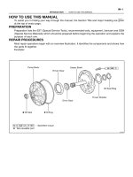
DRAWING
EC03C–05
B01531
Clean Hose
Cylinder Head Side
B01532
Clean Hose
Intake
Manifold
Side
S01846
EC–4
–EMISSION CONTROL (5S–FE) POSITIVE CRANKCASE VENTILATION (PCV)
SYSTEM
1402AuthorĂ: DateĂ:
POSITIVE CRANKCASE
VENTILATION (PCV) SYSTEM
INSPECTION
1. INSPECT PCV VALVE
(a) Remove the PCV valve.
(b) Install a clean hose to the PCV valve.
(c) Inspect the PCV valve operation.
(1) Blow air into the cylinder head side, and check that
air passes through easily.
CAUTION:
Do not suck air through the valve. Petroleum substances
inside the valve are harmful.
(2) Blow air into the intake manifold side, and check
that air passes through with difficulty.
If operation is not as specified, replace the PCV valve.
(d) Remove the clean hose from the PCV valve.
(e) Reinstall the PCV valve.
2. INSPECT HOSES, CONNECTIONS AND GASKETS
Visually check for cracks, leaks or damage.
EC03D–05
B06534
Vapor Pressure Sensor
Connector
VSV for Vapor Pressure Sensor
Connector
EVAP Line Hose
Vent Line Hose
Air Inlet Line Hose
Purge Line Hose
Air Drain Hose
39.2 (400, 29)
N·m (kgf·cm, ft·lbf) : Specified torque
Charcoal Canister
Assembly
Charcoal Canister
Vapor Pressure Sensor
Mounting Bolt
–EMISSION CONTROL (5S–FE) EVAPORATIVE EMISSION (EVAP) CONTROL SYSTEM
EC–5
1403AuthorĂ: DateĂ:
EVAPORATIVE EMISSION (EVAP) CONTROL SYSTEM
COMPONENTS
EC03E–05
B01082
B04812 B06707
Type A
Type B
Gasket
Gasket
B06544
Vacuum
Gauge
S05331
EC–6
–EMISSION CONTROL (5S–FE) EVAPORATIVE EMISSION (EVAP) CONTROL SYSTEM
1404AuthorĂ: DateĂ:
INSPECTION
1. INSPECT LINES AND CONNECTORS
Visually check for loose connections, sharp bends or damage.
2. INSPECT FUEL TANK FILLER PIPE
Visually check for deformation, cracks or fuel leakage.
3. INSPECT FUEL TANK CAP
Visually check if the cap and/or gasket are deformed or dam-
aged.
If necessary, repair or replace the cap.
4. INSPECT EVAP SYSTEM LINE
(a) Warm up the engine and stop the engine.
Allow the engine to warm up to normal operating tempera-
ture.
(b) Install a vacuum gauge (EVAP control system test equip-
ment vacuum gauge) to the EVAP service port on the
purge line.
(c) TOYOTA Hand–Held Tester:
Forced driving of the VSV for the EVAP.
(1) Connect a TOYOTA hand–held tester to the DLC3.
(2) Start the engine.
(3) Push the TOYOTA hand–held tester main switch
ON.
(4) Use the ACTIVE TEST mode on the TOYOTA
hand–held tester to operate the VSV for the EVAP.
B06548
Battery
B06545
B06543
Hose Clipper
Air Drain Hose
–EMISSION CONTROL (5S–FE) EVAPORATIVE EMISSION (EVAP) CONTROL SYSTEM
EC–7
1405AuthorĂ: DateĂ:
(d) If you have no TOYOTA Hand–Held Tester:
Forced driving of the VSV for the EVAP.
(1) Disconnect the VSV connector for the EVAP.
(2) Connect the positive (+) and negative (–) leads from
the battery to the VSV terminals for the EVAP.
(3) Start the engine.
(e) Check the vacuum at idle.
Vacuum:
Maintain at 0.368 – 19.713 in.Hg (5 – 268 in.Aq) for over
5 seconds
HINT:
If the vacuum does not change, you can conclude that the hose
connecting the VSV to the service port has come loose or is
blocked, or the VSV is malfunctioning.
(f) TOYOTA Hand–Held Tester:
Conclude forced driving of the VSV for the EVAP.
(1) Stop the engine.
(2) Disconnect the TOYOTA hand–held tester from the
DLC3.
(g) If you have no TOYOTA Hand–Held Tester:
Conclude forced driving of the VSV for the EVAP.
(1) Stop the engine.
(2) Disconnect the positive (+) and negative (–) leads
from the battery from the VSV terminals for the
EVAP.
(3) Connect the VSV connector for the EVAP.
(h) Disconnect the vacuum gauge from the EVAP service
port on the purge line.
(i) Connect a pressure gauge to the EVAP service port on
the purge line.
(j) Check the pressure.
(1) Close off the air drain hose at the marked position
of the canister with a hose clipper or similar instru-
ment.
B06546
Pressure
Gauge
Pressure
B06547
Fuel Tank Cap
B01250
Air
Disconnect
EVAP Line Hose
B01251
Air
Disconnect
Cap
Disconnect
EVAP Line Hose
Purge Line Hose
Purge Port
EC–8
–EMISSION CONTROL (5S–FE) EVAPORATIVE EMISSION (EVAP) CONTROL SYSTEM
1406AuthorĂ: DateĂ:
(2) Add the pressure (13.5 – 15.5 in.Aq) from the EVAP
service port.
Pressure:
2 minutes after the pressure is added, the gauge
should be over 7.7 – 8.8 in.Aq.
HINT:
If you can’t add pressure, you can conclude that the hose con-
necting the VSVXcanisterXfuel tank has slipped off or the
VSV is open.
(3) Check if the pressure decreases when the fuel tank
cap is removed while adding pressure.
HINT:
If the pressure does not decrease when the filler cap is re-
moved, then you can conclude that the hose connecting the
service port to the fuel tank is blocked, etc.
(k) Disconnect the pressure gauge from the EVAP service
port on the purge line.
5. CHECK AIRTIGHTNESS IN FUEL TANK AND FILLER
PIPE
(a) Disconnect the EVAP line hose from the charcoal canister
side and then pressurize and make the internal pressure
in the fuel tank 4 kPa (41 gf/cm
2
, 0.58 psi).
(b) Check that the internal pressure of the fuel tank can be
hold for 1 minute.
(c) Check the connected portions of each hose and pipe.
(d) Check the installed parts on the fuel tank.
If there is no abnormality, replace the fuel tank and filler pipe.
(e) Reconnect the EVAP line hose to the charcoal canister.
6. INSPECT FUEL CUTOFF VALVE AND FILL CHECK
VALVE
(a) Disconnect the purge line hose and EVAP line hose from
the charcoal canister.
(b) Plug the cap to the air drain hose.
(c) Pressurize 4 kPa (41 gf/cm
2
, 0.58 psi) to the purge port
and check that there is ventilation through the EVAP line
hose.
B01252
Air
Disconnect
Air Inlet Line Hose
B01253
Pinch
Push
AA
Pinch
B01148
B01149
Air
Purge Port
Vent Port
Air Drain Port
Cap
EVAP
Port
–EMISSION CONTROL (5S–FE) EVAPORATIVE EMISSION (EVAP) CONTROL SYSTEM
EC–9
1407AuthorĂ: DateĂ:
HINT:
In the condition that the fuel fuel is full, as the float value of the
fill check valve is closed and has no ventilation, it is necessary
to check the fuel amount (volume).
(d) Check if there is any struck in the vent line hose and EVAP
line hose.
If there is no stuck in hoses, replace the fuel cutoff valve and fill
check valve.
(e) Reconnect the purge line hose and EVAP line hose to the
charcoal canister.
7. CHECK AIR INLET LINE
(a) Disconnect the air inlet line hose from the charcoal canis-
ter.
(b) Check that there is ventilation in the air inlet line.
(c) Reconnect the air inlet line hose to the charcoal canister.
8. REMOVE CHARCOAL CANISTER ASSEMBLY
(a) Disconnect the VSV connector.
(b) Disconnect the vapor pressure sensor connector.
(c) Disconnect the purge line hose, EVAP line hose and air
inlet line hose from the charcoal canister.
(d) Disconnect the vent line hose from the charcoal canister.
(1) Push the connector deep inside.
(2) Pinch portion A.
(3) Pull out the connector.
(e) Remove the 2 charcoal canister mounting bolts.
(f) Remove the vapor pressure sensor mounting bolt.
(g) Remove the charcoal canister assembly.
9. INSPECT CHARCOAL CANISTER
(a) Visually check the charcoal canister for cracks or dam-
age.
(b) Inspect the charcoal canister operation.
(1) Plug the vent port with a cap.
(2) While holding the purge port closed, blow air (1.76
kPa, 18 gf/cm
2
, 0.26 psi) into the EVAP port and
check that air flows from the air drain port.
B01150
Air
Purge Port
EVAP
Port
Air Drain Port
Air Inlet Port
B01151
Vacuum
Purge Port
Air Inlet Port
B01152
Vacuum
Purge Port
EVAP
Port
Air Inlet Port
EC–10
–EMISSION CONTROL (5S–FE) EVAPORATIVE EMISSION (EVAP) CONTROL SYSTEM
1408AuthorĂ: DateĂ:
(3) While holding the purge port and the air drain port
closed, blow air (1.76 kPa, 18 gf/cm
2
, 0.26 psi) into
the EVAP port and check that air does not flow from
the air inlet port.
(4) Apply vacuum (3.43 kPa, 25.7 mmHg, 1.01 in.Hg)
to the purge port, check that the vacuum does not
decrease when the air inlet port is closed, and
check that the vacuum decreases when the air inlet
port is released.
(5) While holding the air inlet port closed, apply vacuum
(3.43 kPa, 25.7 mmHg, 1.01 in.Hg) to the EVAP port
and check that air flows into the purge port.
If operation is not as specified, replace the charcoal canister.
(6) Remove the cap from the vent port.
10. INSPECT VSV FOR EVAP (See page SF–45)
11. INSPECT VSV FOR VAPOR PRESSURE SENSOR
(See page SF–47)
12. INSPECT VAPOR PRESSURE SENSOR
(See page SF–55)
13. REINSTALL CHARCOAL CANISTER ASSEMBLY
EC03F–03
S05556
EGR Valve
Vacuum Hose
Vacuum Hose
EGR Valve
S Gasket
S Non–reusable part
S Gasket
–EMISSION CONTROL (5S–FE) EXHAUST GAS RECIRCULATION (EGR) SYSTEM
EC–11
1409AuthorĂ: DateĂ:
EXHAUST GAS RECIRCULATION (EGR) SYSTEM
COMPONENTS
EC03G–04
S05568
Cap
Filter
B06540
Vacuum Gauge
3–Way Connector
A07370
SST
E1
TE1
B06541
HOT
High Vacuum at 2,500 rpm
Port R
Disconnect
EC–12
–EMISSION CONTROL (5S–FE) EXHAUST GAS RECIRCULATION (EGR) SYSTEM
1410AuthorĂ: DateĂ:
INSPECTION
1. INSPECT EGR SYSTEM
(a) Inspect and clean the filter in the EGR vacuum modulator.
(1) Remove the cap and filter.
(2) Check the filter for contamination or damage.
(3) Using compressed air, clean the filter.
(4) Reinstall the filter and cap.
HINT:
Install the filter with the coarser surface facing the atmospheric
side (outward).
(b) Using a 3–way connector, connect a vacuum gauge to the
hose between the EGR valve and VSV.
(c) Inspect seating of the EGR valve.
Start the engine and check that the engine starts and runs
at idle.
(d) Using SST, connect terminals TE1 and E1 of the DLC1.
SST 09843–18020
(e) Inspect the VSV operation with the cold engine.
(1) The engine coolant temperature should be below
55°C (131°F).
(2) Check that the vacuum gauge indicates zero at
2,500 rpm.
(f) Inspect the operation of the VSV and EGR vacuum modu-
lator with the hot engine.
(1) Warm up the engine to above 60°C (140°F).
(2) Check that the vacuum gauge indicates low vacu-
um at 2,500 rpm.
(3) Disconnect the vacuum hose port R of the EGR vac-
uum modulator and connect port R directly to the in-
take manifold with another hose.
(4) Check that the vacuum gauge indicates high vacu-
um at 2,500 rpm.
B06539
Disconnect
S05567
Air
Engine Stopped
S05566
Engine at
2,500 rpm
Air
–EMISSION CONTROL (5S–FE) EXHAUST GAS RECIRCULATION (EGR) SYSTEM
EC–13
1411AuthorĂ: DateĂ:
HINT:
As a large amount of exhaust gas enters, the engine will misfire
slightly.
(g) Remove the vacuum gauge, and reconnect the vacuum
hoses to the proper locations.
(h) Inspect the EGR valve.
(1) Apply vacuum directly to the EGR valve with the en-
gine idling.
(2) Check that the engine runs rough or dies.
(3) Reconnect the vacuum hoses to the proper loca-
tions.
HINT:
As exhaust gas is increasingly recirculated, the engine will start
to misfire.
(i) Remove the SST from the DLC1.
SST 09843–18020
2. INSPECT EGR VACUUM MODULATOR
(a) Disconnect the vacuum hoses from ports P, Q and R of
the EGR vacuum modulator.
(b) Block ports P and R with your finger.
(c) Blow air into port Q, and check that the air passes through
to the air filter side freely.
(d) Start the engine, and maintain speed at 2,500 rpm.
(e) Repeat the above test. Check that there is a strong resis-
tance to air flow.
(f) Reconnect the vacuum hoses to the proper locations.
S05559
EC–14
–EMISSION CONTROL (5S–FE) EXHAUST GAS RECIRCULATION (EGR) SYSTEM
1412AuthorĂ: DateĂ:
3. INSPECT EGR VALVE
(a) Remove the EGR valve.
(1) Disconnect the 2 vacuum hoses from the EGR
valve.
(2) Remove the 2 bolts, 2 nuts, EGR valve and 2 gas-
kets.
(b) Check the EGR valve for sticking and heavy carbon de-
posits.
If a problem is found, replace the valve.
(c) Reinstall the EGR valve.
(1) Temporarily 2 new gasket and the EGR valve with
the 2 nuts and 2 bolts.
(2) Tighten the nuts.
Torque: 13.3 N·m (136 kgf·cm, 10 ft·lbf)
(3) Tighten the bolts.
Torque: 10 N·m (102 kgf·cm, 7 ft·lbf)
(4) Connect the 2 vacuum hoses to the EGR valve.
4. INSPECT VSV FOR EGR (See page SF–43)
EC03H–03
–EMISSION CONTROL (5S–FE) THREE–WAY CATALYTIC CONVERTER (TWC)
SYSTEM
EC–15
1413AuthorĂ: DateĂ:
THREE–WAY CATALYTIC CONVERTER (TWC) SYSTEM
ON–VEHICLE INSPECTION
1. INSPECT EXHAUST PIPE ASSEMBLY
(a) Check the connections for looseness or damage.
(b) Check the clamps for weakness, cracks or damage.
2. INSPECT REAR TWC
Check for dents or damage.
If any part of the protector is damaged or dented to the extent that it contacts the TWC, repair or replace
it.
3. INSPECT REAR TWC HEAT INSULATOR
(a) Check the heat insulator for damage.
(b) Check for adequate clearance between the catalytic converter and heat insulator.
EC03I–04
B06537
Front TWC (California)
Exhaust Manifold
(Front TWC)
No.3 Exhaust
Manifold Heat
Insulator
No.2 Exhaust
Manifold Stay
A/F Sensor
S Gasket
A/F Sensor Connector
S Gasket
Clamp
x 6
S
S
N·m (kgf·cm, ft·lbf)
S Non–reusable part
49 (500, 36)
44 (450, 32)
62 (630,46)
: Specified torque
No.1 Exhaust
Manifold Stay
S
No.1 Exhaust Manifold
Heat Insulator
No.2 Exhaust Manifold
Heat Insulator
(TMC Made)
(TMMK Made)
EC–16
–EMISSION CONTROL (5S–FE) THREE–WAY CATALYTIC CONVERTER (TWC)
SYSTEM
1414AuthorĂ: DateĂ:
COMPONENTS
B06538
N·m (kgf·cm, ft·lbf)
S Non–reusable part
TWC (Except California)
Rear TWC (California)
S Gasket
Bracket
TWC (Except California)
Rear TWC (California)
Front Exhaust Pipe
S Gasket
Stay
62 (630, 46)
56 (570, 41)
: Specified torque
S
S
S
–EMISSION CONTROL (5S–FE) THREE–WAY CATALYTIC CONVERTER (TWC)
SYSTEM
EC–17
1415AuthorĂ: DateĂ:
EC01U–03
–EMISSION CONTROL (1MZ–FE) EMISSION CONTROL SYSTEM
EC–1
1416AuthorĂ: DateĂ:
EMISSION CONTROL SYSTEM
PURPOSE
The emission control systems are installed to reduce the amount of CO, HC and NOx exhausted from the
engine ((3), (4), (5) and (6)), to prevent the atmospheric release of blow–by gas–containing HC (1) and evap-
orated fuel containing HC being released from the fuel tank (2).
The function of each system is shown in these table.
System Abbreviation Function
(1) Positive Crankcase Ventilation
(2) Evaporative Emission Control
(3) Exhaust Gas Recirculation
(4) Warm Up Three–Way Catalytic Converter
(5) Three–Way Catalytic Converter
(6) Sequential Multiport Fuel Injection*
PCV
EVAP
EGR
WU–TWC
TWC
SFI
Reduces HC
Reduces evaporated HC
Reduces NOx
Reduces HC, CO and NOx
Reduces HC, CO and NOx
Injects a precisely timed, optimum amount of fuel for reduced
exhaust emissions
Remark: * For inspection and repair of the SFI system, refer to the SF section of this manual.
EC01V–03
B06386
VSV for EGR
EGR Valve
Vent Line
Charcoal Canister
Fuel Tank
EVAP Line
Air Drain Hose
Filler Pipe
Air Inlet Line
Purge Line
Cut Off Valve
Fill Check Valve
VSV for EVAP
VCV
Vacuum Surge Tank
EVAP Service Port
Vapor Pressure Sensor
Fuel Tank Cap
VSV for Vapor Pressure Sensor
Vacuum Surge Tank
EC–2
–EMISSION CONTROL (1MZ–FE) PARTS LAYOUT AND SCHEMATIC DRAWING
1417A uthorĂ: DateĂ:
PARTS LAYOUT AND SCHEMATIC DRAWING
LOCATION
EC01W–03
B06721
VSV for Vapor
Pressure Sensor
Vapor Pressure
Sensor
Vacuum Surge
Tank
EGR Valve
Position
Sensor
A/F Sensor
(California A/T)
Heated Oxygen Sensor
(Bank 2 Sensor 1/
Except California A/T)
A/F Sensor
(California A/T)
Heated Oxygen
Sensor
(Bank 1 Sensor 1/
Except California A/T)
Heated Oxygen
Sensor
(Bank 1 Sensor 2)
VCV
TWC
VSV for EVAP
Fuel Tank
Charcoal
Canister
VSV for EGR
WU–TWC
(California A/T)
EVAP Service Port
Purge Line
Air Inlet Line
Air Drain Hose
WU–TWC
(California A/T)
EVAP Line
Vent Line
–EMISSION CONTROL (1MZ–FE) PARTS LAYOUT AND SCHEMATIC DRAWING
EC–3
1418A uthorĂ: DateĂ:
DRAWING
EC01X–03
P02006
Cylinder Head side
Clean Hose
P02477
Air Intake
Chamber Side
P12931
EC–4
–EMISSION CONTROL (1MZ–FE) POSITIVE CRANKCASE VENTILATION (PCV)
SYSTEM
1419AuthorĂ: DateĂ:
POSITIVE CRANKCASE
VENTILATION (PCV) SYSTEM
INSPECTION
1. INSPECT PCV VALVE
(a) Remove the PCV valve.
(b) Install clean hose to the PCV valve.
(c) Inspect the PCV valve operation.
(1) Blow air into the cylinder head side, and check that
air passes through easily.
CAUTION:
Do not suck air through the valve.
Petroleum substances inside the valve are harmful.
(2) Blow air into the air intake chamber side, and check
that air passes through with difficulty.
If operation is not as specified, replace the PCV valve.
(d) Remove clean hose from the PCV valve.
(e) Reinstall the PCV valve.
2. INSPECT HOSES, CONNECTIONS AND GASKETS
Visually check for cracks, leaks or damage.
EC0AU–01
B01507
Vapor Pressure Sensor
Connector
Vapor Pressure Sensor
VSV Connector for Vapor
Pressure Sensor
EVAP Line Hose
Vent Line Hose
Air Inlet Line Hose
Purge Line Hose
Air Drain Hose
VSV for Vapor Pressure Sensor
39.2 (400, 29)
N·m (kgf·cm, ft·lbf) : Specified torque
Charcoal Canister
–EMISSION CONTROL (1MZ–FE) EVAPORATIVE EMISSION (EVAP) CONTROL SYSTEM
EC–5
1420AuthorĂ: DateĂ:
EVAPORATIVE EMISSION (EVAP) CONTROL SYSTEM
COMPONENTS
EC0AV–01
B01082
B04812 B06707
Type A
Type B
Gasket
Gasket
B06544
Vacuum
Gauge
S05331
TOYOTA
Hand–Held Tester
DLC3
EC–6
–EMISSION CONTROL (1MZ–FE) EVAPORATIVE EMISSION (EVAP) CONTROL SYSTEM
1421AuthorĂ: DateĂ:
INSPECTION
1. INSPECT LINES AND CONNECTORS
Visually check for loose connections, sharp bends or damage.
2. INSPECT FUEL TANK FILLER PIPE
Visually check for deformation, cracks or fuel leakage.
3. INSPECT FUEL TANK CAP
Visually check if the cap and/or gasket are deformed or dam-
aged.
If necessary, repair or replace the cap.
4. INSPECT EVAP SYSTEM LINE
(a) Warm up the engine and stop the engine.
Allow the engine to warm up to normal operating tempera-
ture.
(b) Install a vacuum gauge (EVAP control system test equip-
ment vacuum gauge) to the EVAP service port on the
purge line.
(c) TOYOTA Hand–Held Tester:
Forced driving of the VSV for the EVAP.
(1) Connect a TOYOTA hand–held tester to the DLC3.
(2) Start the engine.
(3) Push the TOYOTA hand–held tester main switch
ON.
(4) Use the ACTIVE TEST mode on the TOYOTA
hand–held tester to operate the VSV for the EVAP.
B06722
Battery
B06545
B06543
Hose Clipper
Air Drain Hose
–EMISSION CONTROL (1MZ–FE) EVAPORATIVE EMISSION (EVAP) CONTROL SYSTEM
EC–7
1422AuthorĂ: DateĂ:
(d) If you have no TOYOTA Hand–Held Tester:
Forced driving of the VSV for the EVAP.
(1) Disconnect the VSV connector for the EVAP.
(2) Connect the positive (+) and negative (–) leads from
the battery to the VSV terminals for the EVAP.
(3) Start the engine.
(e) Check the vacuum at idle.
Vacuum:
Maintain at 0.368 – 19.713 in.Hg (5 – 268 in.Aq) for over
5 seconds
HINT:
If the vacuum does not change, you can conclude that the hose
connecting the VSV to the service port has come loose or is
blocked, or the VSV is malfunctioning.
(f) TOYOTA Hand–Held Tester:
Conclude forced driving of the VSV for the EVAP.
(1) Stop the engine.
(2) Disconnect the TOYOTA hand–held tester from the
DLC3.
(g) If you have no TOYOTA Hand–Held Tester:
Conclude forced driving of the VSV for the EVAP.
(1) Stop the engine.
(2) Disconnect the positive (+) and negative (–) leads
from the battery from the VSV terminals for the
EVAP.
(3) Connect the VSV connector for the EVAP.
(h) Disconnect the vacuum gauge from the EVAP service
port on the purge line.
(i) Connect a pressure gauge to the EVAP service port on
the purge line.
(j) Check the pressure.
(1) Close off the air drain hose at the marked position
of the canister with a hose clipper or similar instru-
ment.
B06546
Pressure
Gauge
Pressure
B06547
Fuel Tank Cap
B01250
Air
Disconnect
EVAP Line Hose
B01251
Air
Disconnect
Cap
Disconnect
EVAP Line Hose
Purge Line Hose
Purge Port
EC–8
–EMISSION CONTROL (1MZ–FE) EVAPORATIVE EMISSION (EVAP) CONTROL SYSTEM
1423AuthorĂ: DateĂ:
(2) Add the pressure (13.5 – 15.5 in.Aq) from the EVAP
service port.
Pressure:
2 minutes after the pressure is added, the gauge
should be over 7.7 – 8.8 in.Aq.
HINT:
If you can’t add pressure, you can conclude that the hose con-
necting the VSVXcanisterXfuel tank has slipped off or the
VSV is open.
(3) Check if the pressure decreases when the fuel tank
cap is removed while adding pressure.
HINT:
If the pressure does not decrease when the filler cap is re-
moved, then you can conclude that the hose connecting the
service port to the fuel tank is blocked, etc.
(k) Disconnect the pressure gauge from the EVAP service
port on the purge line.
5. CHECK AIRTIGHTNESS IN FUEL TANK AND FILLER
PIPE
(a) Disconnect the EVAP line hose from the charcoal canister
side and then pressurize and make the internal pressure
in the fuel tank 4 kPa (41 gf/cm
2
, 0.58 psi).
(b) Check that the internal pressure of the fuel tank can be
hold for 1 minute.
(c) Check the connected portions of each hose and pipe.
(d) Check the installed parts on the fuel tank.
If there is no abnormality, replace the fuel tank and filler pipe.
(e) Reconnect the EVAP line hose to the charcoal canister.
6. INSPECT FUEL CUTOFF VALVE AND FILL CHECK
VALVE
(a) Disconnect the purge line hose and EVAP line hose from
the charcoal canister.
(b) Plug the cap to the air drain hose.
(c) Pressurize 4 kPa (41 gf/cm
2
, 0.58 psi) to the purge port
and check that there is ventilation through the EVAP line
hose.