Camry Repair Manual AUTOMATIC TRANSAXLE
Bạn đang xem bản rút gọn của tài liệu. Xem và tải ngay bản đầy đủ của tài liệu tại đây (1.04 MB, 58 trang )
AX034–01
–AUTOMATIC TRANSAXLE (A140E) AUTOMATIC TRANSAXLE SYSTEM
AX–1
1894A uthorĂ: DateĂ:
AUTOMATIC TRANSAXLE SYSTEM
PRECAUTION
If the vehicle is equipped with a mobile communication system, refer to the precautions in the IN section.
AX035–01
D00989
O/D Direct
Clutch (C
0
)
O/D Brake (B
0
)
1st & Reverse Brake (B
3
)
One – Way clutch
No.2 (F
2
)
2nd Brake (B
2
)
Forward
Clutch (C
1
)
2nd Coast brake (B
1
)
Direct Clutch (C
2
)
O/D One – Way
Clutch (F
0
)
O/D Planetary Gear
Counter
Drive Gear
Intermediate
Shaft
Rear
Planetary Gear
One Way Clutch
No.1 (F
1
)
Front Planetary
Gear
Input Shaft
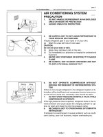
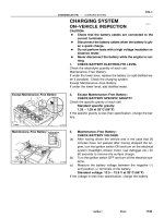
Shift lever
position
Gear position
Parking
Reverse
Neutral
P
R
N
C
1
B
2
B
3
F
0
C
0
C
2
B
0
B
1
F
1
F
2
D
2
L
1st
2nd
3rd
O/D
1st
2nd
*3rd
1st
*2nd
z
z
z
z
z
z
z
z
z
z
z
z
z
z
z
z
z
z
z
z
z
z
zz
z
z
zz zz
zzz
z
z
z
z
z
z
z
zz
z
z
z
z
z
z
z
Planetary Gear Unit
z: Operating
*: Down–shift only in the 3rd gear for the 2 position and 2nd gear for the L position no up–shift.
AX–2
–AUTOMATIC TRANSAXLE (A140E) AUTOMATIC TRANSAXLE SYSTEM
1895A uthorĂ: DateĂ:
OPERATION
Q00207
AX036–01
Q04678
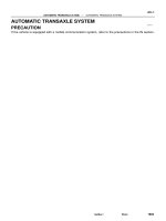
Drive Gear
Vehicle Speed Sensor
O–Ring
Clip
–AUTOMATIC TRANSAXLE (A140E) VEHICLE SPEED SENSOR
AX–3
1896AuthorĂ: DateĂ:
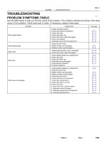
VEHICLE SPEED SENSOR
ON–VEHICLE REPAIR
1. REMOVE AIR CLEANER ASSEMBLY
2. DISCONNECT VEHICLE SPEED SENSOR CONNEC-
TOR
3. REMOVE VEHICLE SPEED SENSOR ASSEMBLY
(a) Remove the bolt and vehicle speed sensor assembly.
(b) Remove the clip and speedometer driven gear from ve-
hicle speed sensor.
(c) Remove the O–ring from vehicle speed sensor.
4. INSTALL VEHICLE SPEED SENSOR ASSEMBLY
(a) Coat a new O–ring with ATF and install it to the vehicle
speed sensor.
(b) Install the speedometer driven gear to the vehicle speed
sensor and clip.
(c) Install the vehicle speed sensor assembly and torque the
bolts.
Torque: 16 N·m (160 kgf·cm, 12 ft·lbf)
5. CONNECT VEHICLE SPEED SENSOR CONNECTOR
6. INSTALL AIR CLEANER ASSEMBLY
Q10050
AX037–01
AX–4
–AUTOMATIC TRANSAXLE (A140E) PARK/NEUTRAL POSITION (PNP) SWITCH
1897AuthorĂ: DateĂ:
PARK/NEUTRAL POSITION (PNP)
SWITCH
ON–VEHICLE REPAIR
1. REMOVE CONTROL SHAFT LEVER
(a) Remove the nut and control cable.
(b) Remove the nut, washer and control shaft lever.
2. DISCONNECT PARK/NEUTRAL POSITION SWITCH
CONNECTOR
3. REMOVE PARK/NEUTRAL POSITION SWITCH
(a) Pry off the lock washer and remove the nut.
(b) Remove the 2 bolts and park/neutral position switch.
4. INSTALL PARK/NEUTRAL POSITION SWITCH
(a) Install the park/neutral position switch with 2 bolts.
Torque: 5.4 N·m (55 kgf·cm, 48 in.·lbf)
(b) Install a new lock plate and the nut.
Torque: 6.9 N·m (70 kgf·cm, 61 in.·lbf)
(c) Bend claws on the lock plate to fix the nut.
(d) Adjust the park/neutral position switch.
(See page DI–389)
5. CONNECT PARK/NEUTRAL POSITION SWITCH CON-
NECTOR
6. INSTALL CONTROL SHAFT LEVER
(a) Install the control shaft lever, washer and nut.
Torque: 13 N·m (130 kgf·cm, 9 ft·lbf)
(b) Install the control cable and nut.
Torque: 15 N·m (150 kgf·cm, 11 ft·lbf)
AX038–01
Q00073
AT0103
Z10944
mm (in.)
14 (0.551)
36 (1.417)
AT2711
Z10940
20
(0.787)
mm (in.)
45
(1.772)
50
(1.969)
AT3336
–AUTOMATIC TRANSAXLE (A140E) VALVE BODY ASSEMBLY
AX–5
1898A uthorĂ: DateĂ:
VALVE BODY ASSEMBLY
ON–VEHICLE REPAIR
1. DRAIN TRANSAXLE FLUID
2. REMOVE OIL PAN AND GASKET
NOTICE:
Some fluid will remain in the oil pan.
Remove the oil pan bolts, and carefully remove the oil pan as-
sembly. Discard the gasket.
3. EXAMINE PARTICLES IN PAN
Remove the magnets and use them to collect any steel chips.
Look carefully at the chips and particles in the pan and on the
magnet to anticipate what type of wear you will find in the trans-
axle.
z Steel (magnetic): bearing, gear and plate wear
z Brass (non–magnetic): bushing wear
4. REMOVE MANUAL VALVE BODY DETENT SPRING
AND MANUAL VALVE BODY
(a) Remove the detent spring on the manual valve body.
(b) Remove the manual valve body.
5. REMOVE OIL STRAINER AND OIL PIPE BRACKET
(a) Remove the 3 bolts and the oil strainer.
(b) Remove the 2 bolts and oil pipe bracket.
NOTICE:
Be careful as oil will come out of the strainer when it is re-
moved.
Z10941
AT0493
AT7868
AT0399
OR0038
Z19291
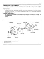
16 (0.63)
Shift Solenoid
Valve No.1
16 (0.63)
Shift Solenoid
Valve No.2
AT3008
mm (in.)
AX–6
–AUTOMATIC TRANSAXLE (A140E) VALVE BODY ASSEMBLY
1899A uthorĂ: DateĂ:
6. DISCONNECT SOLENOID CONNECTORS
7. REMOVE OIL PIPES
Pry up the both pipe ends with a large screwdriver and remove
the 4 pipes.
NOTICE:
Be careful not to bend or damage the pipe.
8. REMOVE VALVE BODY
Remove the 12 bolts.
9. REMOVE THROTTLE CABLE
(a) Disconnect the throttle cable.
(b) Remove the valve body.
10. REMOVE 2ND BRAKE APPLY GASKET
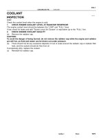
11. REMOVE SHIFT SOLENOID VALVE NO.1 AND NO.2
(a) Remove the 2 bolts and shift solenoid valve No.1.
(b) Remove the bolt and shift solenoid valve No.2.
(c) Remove the 2 O–rings from the shift solenoid valve No.1
and No.2.
OR0038
Z10942
C
D
B
A
C
B
A
B
AT0492
AT7870
Z10941
AT0493
Shift Solenoid Valve No.2
Black
White
Shift Solenoid Valve No.1
–AUTOMATIC TRANSAXLE (A140E) VALVE BODY ASSEMBLY
AX–7
1900A uthorĂ: DateĂ:
12. INSTALL SHIFT SOLENOID VALVE NO.1 AND NO.2
(a) Coat 2 new O–rings with ATF.
(b) Install the 2 O–rings to the shift solenoid valve No.1 and
No.2.
(c) Install the shift valve No.1 with the 2 bolts.
Torque: 5.4 N·m (55 kgf·cm, 48 in.·lbf)
(d) Install the shift valve No.2 with the bolt.
Torque: 5.4 N·m (55 kgf·cm, 48 in.·lbf)
13. INSTALL NEW 2ND BRAKE APPLY GASKET
14. INSTALL VALVE BODY
(a) While holding the cam down by your hand, slip the cable
end into the slot.
NOTICE:
Do not entangle the solenoid wire.
(b) Install the valve body with the 12 bolts.
HINT:
Temporarily install the 12 bolts first, then tighten the 12 bolts.
Torque: 10 N·m (100 kgf·cm, 7 ft·lbf)
Bolt length:
Bolt A: 20 mm (0.79 in.)
Bolt B: 25 mm (0.98 in.)
Bolt C: 36 mm (1.42 in.)
Bolt D: 50 mm (1.97 in.)
15. INSTALL OIL PIPES
Using a plastic hammer, install the 4 pipes into the positions in-
dicated in the illustration.
NOTICE:
Be careful not to bend or damage the pipes.
16. CONNECT SOLENOID CONNECTORS
Connect the black wire harness to shift solenoid valve No.2 and
white wire harness to shift solenoid valve No.1.
Z10940
mm (in.)
20
(0.78)
45
(1.772)
50
(1.969)
AT3336
Z10944
mm (in.)
36 (1.417)
14 (0.551)
AT2711
Z10945
Magnets
AT2368
Q00073
AX–8
–AUTOMATIC TRANSAXLE (A140E) VALVE BODY ASSEMBLY
1901A uthorĂ: DateĂ:
17. INSTALL OIL STRAINER AND OIL PIPE BRACKET
(a) Install the 2 bolts and oil pipe bracket.
Torque: 10 N·m (100 kgf·cm, 7 ft·lbf)
(b) Install the 3 bolts and oil strainer.
Torque: 10 N·m (100 kgf·cm, 7 ft·lbf)
18. INSTALL MANUAL VALVE BODY DETENT SPRING
AND MANUAL VALVE BODY
(a) Align the manual valve with the pin on the manual shaft
lever.
(b) Lower the manual valve body into place.
(c) Temporarily install the 4 bolts first. Then, tighten them with
a torque wrench.
Torque: 10 N·m (100 kgf·cm, 7 ft·lbf)
(d) Place the detent spring on the manual valve body and
temporarily install the 2 bolts first.
Torque: 10 N·m (100 kgf·cm, 7 ft·lbf)
(e) Check that the manual valve lever is touching the center
of the detent spring tip roller.
19. INSTALL MAGNETS IN OIL PAN
NOTICE:
Make sure that the magnets do not interfere with the oil
pipes.
20. INSTALL OIL PAN AND GASKET
Install a new gasket and oil pan with the 15 bolts.
Torque: 4.9 N·m (50 kgf·cm, 43 in.·lbf)
21. FILL FLUID AND CHECK FLUID LEVEL
(See page DI–389)
AX039–01
Q10052
Q10339
0.8 – 1.5 mm(0.031 – 0.059 in.)
200 mm
(7.87 in.)
–AUTOMATIC TRANSAXLE (A140E) THROTTLE CABLE
AX–9
1902AuthorĂ: DateĂ:
THROTTLE CABLE
ON–VEHICLE REPAIR
1. DISCONNECT THROTTLE CABLE
(a) Disconnect the cable from the throttle linkage.
(b) Disconnect the cable from the cable clamps in the engine
compartment.
2. REMOVE PARK/NEUTRAL POSITION SWITCH
(See page AX–4)
3. REMOVE VALVE BODY (See page AX–5)
4. REMOVE THROTTLE CABLE
(a) Remove the retaining bolt and plate.
(b) Pull out the cable from the transaxle case.
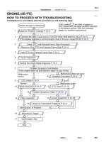
5. IF THROTTLE CABLE IS NEW, STAKE STOPPER OR
PAINT MARK ON INNER CABLE
HINT:
New cable does not have a staked cable stopper.
(a) Bend the cable to ensure a radius of about 200 mm (7.87
in.).
(b) Pull the inner cable lightly until a slight resistance is felt,
and hold it there.
(c) Stake the stopper, 0.8 – 1.5 mm (0.031 – 0.059 in.) from
the end of the outer cable.
(d) Install a new O–ring to the throttle cable.
(e) Push in the throttle cable and install the retaining bolt.
6. INSTALL VALVE BODY (See page AX–5)
7. INSTALL PARK/NEUTRAL POSITION SWITCH
(See page AX–4)
8. CONNECT THROTTLE CABLE
9. FILL FLUID AND CHECK FLUID LEVEL
(See page DI–389)
10. ADJUST THROTTLE CABLE (See page DI–389)
Q10051
AX03A–01
AX–10
–AUTOMATIC TRANSAXLE (A140E) SHIFT SOLENOID VALVE SL
1903A uthorĂ: DateĂ:
SHIFT SOLENOID VALVE SL
ON–VEHICLE REPAIR
1. REMOVE PARK/NEUTRAL POSITION SWITCH
(See page AX–4)
2. DISCONNECT SHIFT SOLENOID VALVE SL CONNEC-
TOR
3. REMOVE SHIFT SOLENOID VALVE SL
(a) Remove the 2 bolts and shift solenoid valve SL.
(b) Remove the 2 O–rings from the shift solenoid valve SL.
4. INSTALL SHIFT SOLENOID VALVE SL
(a) Coat 2 new O–rings with ATF and install them to the shift
solenoid valve SL.
(b) Install the shift solenoid valve SL and 2 bolts.
5. CONNECT SHIFT SOLENOID VALVE SL CONNECTOR
6. INSTALL PARK/NEUTRAL POSITION SWITCH
(See page AX–4)
Q00394
SST
AX03B–01
Q00247
SST
–AUTOMATIC TRANSAXLE (A140E) DIFFERENTIAL OIL SEAL
AX–11
1904A uthorĂ: DateĂ:
DIFFERENTIAL OIL SEAL
ON–VEHICLE REPAIR
1. REMOVE LH AND RH DRIVE SHAFTS
(See page SA–17)
2. REMOVE SIDE GEAR SHAFT OIL SEAL
Using SST, drive out the oil seals on both sides.
SST 09308–00010
3. INSTALL SIDE GEAR SHAFT OIL SEAL
(a) Using SST, drive in a new oil seal.
SST 09350–32014 (09351–32130, 09351–32150)
Oil seal depth:
LH: 2.7 ± 0.5 mm (0.106 ± 0.020 in.)
RH: 0 ± 0.5 mm (0 ± 0.020 in.)
(b) Coat the lip of oil seal with MP grease.
4. INSTALL LH AND RH DRIVE SHAFTS
(See page SA–24)
5. CHECK TRANSAXLE FLUID LEVEL
(See page DI–389)
AX03C–01
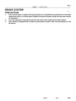
D00760
Shift Lock Override Cover
Shift Lock Override Button
Stop Light Switch
Key Interlock Solenoid
Shift Lock
Control Unit Assembly
AX–12
–AUTOMATIC TRANSAXLE (A140E) SHIFT LOCK SYSTEM (TMC Made)
1905AuthorĂ: DateĂ:
SHIFT LOCK SYSTEM (TMC Made)
LOCATION
AX03D–01
D00758
5 (IG)
4 (KLS
+
)
3 (E)
2 (STP)
1 (ACC)
Wire Harness Side
Q09456
1 (KLS
+
)
2 (E)
Q09457
1 (KLS
+
)
2 (E)
–AUTOMATIC TRANSAXLE (A140E) SHIFT LOCK SYSTEM (TMC Made)
AX–13
1906AuthorĂ: DateĂ:
INSPECTION
1. INSPECT SHIFT LOCK CONTROL UNIT ASSEMBLY
Using a voltmeter, measure the voltage at each terminal.
HINT:
Do not disconnect the shift lock control unit assembly connec-
tor.
Terminal Measuring Condition Voltage (V)
1 – 3 (ACC – E) Ignition switch ACC 10 – 14
5 – 3 (IG – E) Ignition switch ON 10 – 14
2 – 3 (STP – E) Depressing brake pedal 10 – 14
4 – 3 (KLS
+
– E)
(1) Ignition switch ACC and P position
(2) Ignition switch ACC and except P position
(3) Ignition switch ACC and except P position (After approx. 1 second)
0
7.5 – 11
6 – 9.5
2. INSPECT KEY INTERLOCK SOLENOID
(a) Disconnect the solenoid connector.
(b) Using an ohmmeter, measure resistance between termi-
nals.
Standard resistance: 12.5 – 16.5 Ω
If resistance value is not as specified, replace the solenoid.
(c) Apply battery positive voltage between terminals. Check
that an operation noise can be heard from the solenoid.
If the solenoid does not operate, replace the solenoid.
AX03E–01
D00759
Shift Lock Override Cover
Shift Lock Override Button
Shift Lock Solenoid
Shift Lock Control Switch
Shift Lock Control ECU
Key Interlock Solenoid
Stop Light Switch
AX–14
–AUTOMATIC TRANSAXLE (A140E) SHIFT LOCK SYSTEM (TMMK Made)
1907AuthorĂ: DateĂ:
SHIFT LOCK SYSTEM (TMMK Made)
LOCATION
AX03F–01
Q09459
4 (P2)
2 (SLS
+
)
5 (SLS
–
)
3 (P1)
3 (IG)
6 (STP)
1 (ACC)
4 (KLS
+
)
1 (P)
Back Side
Front Side
A
B
Q09460
2 (SLS
+
)
5 (SLS
–
)
Q09461
2 (SLS
+
)
5 (SLS
–
)
–AUTOMATIC TRANSAXLE (A140E) SHIFT LOCK SYSTEM (TMMK Made)
AX–15
1908AuthorĂ: DateĂ:
INSPECTION
1. INSPECT SHIFT LOCK CONTROL ECU
Using a voltmeter, measure voltage at each terminal.
HINT:
Do not disconnect the ECU connector.
Terminal Measuring Condition Voltage (V)
A, 1 – A, 5 (ACC – E) Ignition switch ACC 10 – 14
A, 3 – A, 5 (IG – E) Ignition switch ON 10 – 14
A, 6 – A, 5 (STP – E) Depressing brake pedal 10 – 14
A, 4 – A, 5 (KLS
+
– E)
(1) Ignition switch ACC and P position
(2) Ignition switch ACC and except P position
(3) Ignition switch ACC and except P position (After approx. 1 second)
0
7.5 – 11
6 – 9.5
B, 2 – B, 5 (SLS
+
– SLS
–
)
(1) Ignition switch ON and P position
(2) Depress brake pedal
(3) Except P position
0
8 – 13.5
0
B, 3 – B, 1 (P1 – P)
(1) Ignition switch ON, P position and depressing brake pedal
(2) Shift except P position under conditions above
0
9 – 13.5
B, 4 – B, 1 (P2 – P)
(1) Ignition switch ACC, P position
(2) Shift except P position under conditions above
9 – 13.5
0
2. INSPECT SHIFT LOCK SOLENOID
(a) Disconnect the solenoid connector.
(b) Using an ohmmeter, measure resistance between termi-
nals.
Standard resistance: 29 – 35 Ω
If resistance value is not as specified, replace the solenoid.
(c) Apply battery positive voltage between terminals. Check
that operation noise can be heard from the solenoid.
If the solenoid does not operate, replace the solenoid.
Q09456
2 (E)
1 (KLS
+
)
Q09457
2 (E)
1 (KLS
+
)
Q09464
3 (P1)
4 (P2) 1 (P)
AX–16
–AUTOMATIC TRANSAXLE (A140E) SHIFT LOCK SYSTEM (TMMK Made)
1909AuthorĂ: DateĂ:
3. INSPECT KEY INTERLOCK SOLENOID
(a) Disconnect the solenoid connector.
(b) Using an ohmmeter, measure resistance between termi-
nals.
Standard resistance: 12.5 – 16.5 Ω
If resistance value is not as specified, replace the solenoid.
(c) Apply battery positive voltage between terminals. Check
that an operation noise can be heard from the solenoid.
If the solenoid does not operate, replace the solenoid.
4. INSPECT SHIFT LOCK CONTROL SWITCH
Inspect that there is continuity between each terminal.
Shift position Tester connection Specified value
P position (Release
button is not pushed)
1 – 3 (P – P1) Continuity
P position (Release
button is pushed)
1 – 3 (P – P1)
1 – 4 (P – P2)
Continuity
R, N, D, 2, L position 1 – 4 (P – P2) Continuity
If continuity is not as specified, replace the switch.
AX03G–01
Q10053
14 (145, 10)
No.1 Exhaust Pipe Support Bracket
Clip
Engine Hood
Air Cleaner Assembly
14 (145, 10)
Starter
Cruise Control Actuator
RH Drive Shaft
42 (430, 31)66 (670, 48)
39 (400, 29)
39 (400, 29)
39 (400, 29)
Hold Down Clamp
Manifold Stay
Stiffener
Plate
Battery
Battery Tray
z Snap Ring
z
32 (330, 24)
27 (280, 20)
Torque Converter
Clutch
x6
42 (430, 31)
42 (430, 31)
Stiffener Plate
66 (670, 48)
42 (430, 31)
Exhaust
Manifold Stay
66 (670, 48)
z Snap Ring
LH Drive Shaft
Plug for Line Pressure Test
Rear End Plate
15 (150, 11)
19 (195, 14)
25 (250, 18)
Oil Pan Insulator
Shift Control Cable
N·m (kgf·cm, ft·lbf)
: Specified torque
z Non–reusable part
TMMK
TMC
–AUTOMATIC TRANSAXLE (A140E) AUTOMATIC TRANSAXLE UNIT
AX–17
1910A uthorĂ: DateĂ:
AUTOMATIC TRANSAXLE UNIT
COMPONENTS
Q10054
RH Fender Apron seal
RR Engine Mounting
Stabilizer Bar
10 (100, 7)
RH Rear
Lower Brace
Steering Return Pipe
19 (195, 14)
FR Engine Mounting
Stabilizer Bar Link
Front Suspension
Member
z
Front Exhaust Pipe
RH Front Lower Brace
LH Engine Mounting
66 (670, 48)
64 (650, 47)
39 (400, 29)
181 (1,850, 134)
LH Rear Lower Brace
32 (330, 24)
36 (370, 27)
181 (1,850, 134)
127 (1,300, 94)
80 (820, 59)
TMC Made : 80 (820, 59)
TMMK Made :
Green Color Bolt : 66 (670, 48)
Silver Color Bolt : 44 (450, 32)
TMC Made : 80 (820, 59)
TMMK Made :
Green Color Bolt : 66 (670, 48)
Silver Color Bolt : 44 (450, 32)
LH Front
Lower Brace
36 (370, 27)
181 (1,850, 134)
56 (570, 41)
z
z
z
z Gasket
62 (630, 46)
Tie Rod End
Lock Nut Cap
Engine Under Cover
LH Fender Liner
z Gasket
z
Exhaust Pipe No.1 Support Bracket
33 (330, 24)
33 (330, 24)
Exhaust Pipe
Clamp
LH Fender Liner
LH Fender Apron Seal
z Cotter Pin
49 (500, 36)
294 (3,000, 217)
Center Engine Under Cover
N·m (kgf·cm, ft·lbf)
: Specified torque
z Non–reusable part
AX–18
–AUTOMATIC TRANSAXLE (A140E) AUTOMATIC TRANSAXLE UNIT
1911A uthorĂ: DateĂ:
AX03H–01
Q10055
Q00211
Q10056
Q10057
–AUTOMATIC TRANSAXLE (A140E) AUTOMATIC TRANSAXLE UNIT
AX–19
1912A uthorĂ: DateĂ:
REMOVAL
1. REMOVE BATTERY
2. REMOVE AIR CLEANER ASSEMBLY
3. DISCONNECT THROTTLE CABLE
4. w/ CRUISE CONTROL:
REMOVE CRUISE CONTROL ACTUATOR
(a) Disconnect the connector.
(b) Remove the 3 bolts and disconnect cruise control actua-
tor with the bracket.
5. DISCONNECT OIL COOLER HOSE
6. DISCONNECT VEHICLE SPEED SENSOR CONNEC-
TOR
7. DISCONNECT PARK/NEUTRAL POSITION SWITCH
CONNECTOR
8. DISCONNECT SHIFT SOLENOID VALVE NO.1 AND
NO.2 CONNECTOR
9. DISCONNECT SHIFT SOLENOID VALVE SL CONNEC-
TOR
10. REMOVE 2 FRONT SIDE ENGINE MOUNTING BOLTS
Torque:
TMC made: 80 N·m (820 kgf·cm, 59 ft·lbf)
TMMK made:
Green color bolt: 66 N·m (670 kgf·cm, 48 ft·lbf)
Silver color bolt: 44 N·m (450 kgf·cm, 32 ft·lbf)
11. DISCONNECT 2 GROUND CABLES
12. REMOVE STARTER
(a) Disconnect the connector and remove the nut.
(b) Remove the 2 bolts, shift cable clamp and starter.
Torque: 39 N·m (400 kgf·cm, 29 ft·lbf)
13. REMOVE 3 TRANSAXLE–TO–ENGINE BOLTS
Torque: 66 N·m (670 kgf·cm, 48 ft·lbf)
Q10058
Q10059
Q00251
AX–20
–AUTOMATIC TRANSAXLE (A140E) AUTOMATIC TRANSAXLE UNIT
1913A uthorĂ: DateĂ:
14. REMOVE EXHAUST MANIFOLD STAY
Remove the 2 bolts and exhaust manifold stay.
Torque: 42 N·m (430 kgf·cm, 31 ft·lbf)
15. REMOVE TRANSAXLE–TO–ENGINE BOLT
Torque: 66 N·m (670 kgf·cm, 48 ft·lbf)
16. REMOVE ENGINE HOOD
(a) Disconnect the washer pipe.
(b) Remove the 4 bolts and engine hood.
Torque: 14 N·m (145 kgf·cm, 10 ft·lbf)
17. RAISE AND SUPPORT VEHICLE SECURELY
18. REMOVE FRONT WHEELS
Torque: 103 N·m (1,050 kgf·cm, 76 ft·lbf)
19. REMOVE ENGINE UNDER COVER AND CENTER EN-
GINE UNDER COVER
20. DISCONNECT SHIFT CONTROL CABLE
(a) Remove the nut and disconnect the shift control cable
from the park/neutral position switch.
Torque: 15 N·m (150 kgf·cm, 11 ft·lbf)
(b) Remove the clip and disconnect the shift control cable
from the bracket.
21. REMOVE DIFFERENTIAL FLUID DRAIN PLUG AND
GASKET
HINT:
At the time of installation, please refer to the following item.
Replace the used gasket with a new gasket.
22. DRAIN DIFFERENTIAL FLUID
23. REMOVE LH AND RH FENDER APRON SEALS
24. REMOVE LH AND RH DRIVE SHAFTS
(See page SA–17)
Q10060
Q00068
Q08532
Q10061
–AUTOMATIC TRANSAXLE (A140E) AUTOMATIC TRANSAXLE UNIT
AX–21
1914A uthorĂ: DateĂ:
25. REMOVE EXHAUST FRONT PIPE
(a) Remove the 2 nuts and exhaust front pipe clamp.
Torque: 33 N·m (330 kgf·cm, 24 ft·lbf)
(b) Remove the 2 bolts and exhaust pipe No.1 support brack-
et.
Torque: 33 N·m (330 kgf·cm, 24 ft·lbf)
(c) Remove the 3 nuts.
Torque: 62 N·m (630 kgf·cm, 46 ft·lbf)
HINT:
At the time of installation, please refer to the following item.
Replace the used nuts with new ones.
(d) Remove the 2 bolts, nuts and front exhaust pipe.
Torque: 56 N·m (570 kgf·cm, 41 ft·lbf)
HINT:
At the time of installation, please refer to the following item.
Replace the used nuts with new ones.
(e) Remove the 2 gaskets.
HINT:
At the time of installation, please refer to the following item.
Replace the used gaskets with new ones.
26. REMOVE FRONT SIDE ENGINE MOUNTING INSULA-
TOR BOLT
Torque:
TMC made: 80 N·m (820 kgf·cm, 59 ft·lbf)
TMMK made:
Green color bolt: 66 N·m (670 kgf·cm, 48 ft·lbf)
Silver color bolt: 44 N·m (450 kgf·cm, 32 ft·lbf)
27. REMOVE REAR SIDE ENGINE MOUNTING NUT
(a) Remove the 2 grommets.
(b) Remove the 3 nuts.
Torque: 66 N·m (670 kgf·cm, 48 ft·lbf)
28. REMOVE LEFT SIDE TRANSAXLE MOUNTING NUT
(a) Remove the 2 grommets.
(b) Remove the 2 nuts.
Torque: 80 N·m (820 kgf·cm, 59 ft·lbf)
Q10062
Q10063
Q06479
Q10041
Q10037
AX–22
–AUTOMATIC TRANSAXLE (A140E) AUTOMATIC TRANSAXLE UNIT
1915A uthorĂ: DateĂ:
29. REMOVE STEERING GEAR HOUSING
(a) Remove the 4 bolts, LH and RH stabilizer bar brackets
and bushings.
Torque:19 N·m (195 kgf·cm, 14 ft·lbf)
(b) Remove the front stabilizer bar. (See page SA–48)
(c) Remove the 2 steering gear housing mounting bolts and
nuts.
Torque: 181 N·m (1,850 kgf·cm, 134 ft·lbf)
30. TIE STEERING GEAR HOUSING TO REAR ENGINE
MOUNTING BRACKET BY CORD OR EQUIVALENT
31. ATTACH ENGINE SLING DEVICE TO ENGINE HANG-
ERS
CAUTION:
Do not attempt to hang the engine by hooking the chain to
any other part.
32. REMOVE FRONT FRAME ASSEMBLY
(a) Remove the 2 bolts and steering return pipe mounting
brackets.
Torque: 10 N·m (100 kgf·cm, 7 ft·lbf)
(b) Remove the screws and turn over the front side of the LH
and RH fender liners.
(c) Remove the screws and turn over the rear side of LH and
RH fender liners.
Q10172
Front
Q10064
Rear
Q10065
TMC : Bolt
TMMK : Nut
–AUTOMATIC TRANSAXLE (A140E) AUTOMATIC TRANSAXLE UNIT
AX–23
1916A uthorĂ: DateĂ:
(d) Remove the 6 bolts and 4 nuts.
Torque:
19 mm head bolt: 181 N·m (1,850 kgf·cm, 134 ft·lbf)
14 mm head bolt: 32 N·m (330 kgf·cm, 24 ft·lbf)
Nut: 36 N·m (370 kgf·cm, 27 ft·lbf)
(e) Remove the front frame assembly.
33. SUPPORT TRANSAXLE WITH A TRANSMISSION
JACK
34. REMOVE FRONT SIDE STIFFENER PLATE
TMMK made:
Remove the nut, 2 bolts and stiffener plate.
Torque: 42 N·m (430 kgf·cm, 31 ft·lbf)
TMC made:
Remove the 3 bolts and stiffener plate.
Torque: 42 N·m (430 kgf·cm, 31 ft·lbf)
35. REMOVE REAR END PLATE
(a) Remove the 2 bolts and No.1 exhaust pipe support brack-
et.
Torque: 19 N·m (195 kgf·cm, 14 ft·lbf)
(b) Remove the 2 bolts and rear end plate with oil pan insula-
tor.
Torque: 25 N·m (250 kgf·cm, 18 ft·lbf)
Q10066
AX–24
–AUTOMATIC TRANSAXLE (A140E) AUTOMATIC TRANSAXLE UNIT
1917A uthorĂ: DateĂ:
36. REMOVE TORQUE CONVERTER CLUTCH MOUNT-
ING BOLT
Turn the crankshaft to gain access to each bolt, remove the 6
bolts with holding the crankshaft pulley set bolt by a wrench.
Torque: 27 N·m (280 kgf·cm, 20 ft·lbf)
HINT:
At the time of installation, please refer to the following item.
First the install black colored bolt and then the 5 other bolts.
37. REMOVE REAR SIDE STIFFENER PLATE
(a) Remove the 2 bolts and manifold stay.
Torque: 39 N·m (400 kgf·cm, 29 ft·lbf)
(b) Remove the 4 bolts and stiffener plate.
Torque: 39 N·m (400 kgf·cm, 29 ft·lbf)
38. REMOVE TRANSAXLE ASSEMBLY
Separate the transaxle and engine, and lower the transaxle.
AX03I–01
AT3412
–AUTOMATIC TRANSAXLE (A140E) AUTOMATIC TRANSAXLE UNIT
AX–25
1918A uthorĂ: DateĂ:
INSTALLATION
1. CHECK TORQUE CONVERTER CLUTCH INSTALLA-
TION
Using a scale and a straight edge, measure to the distance from
the installed surface to the transaxle housing.
Correct distance: 13.0 mm (0.512 in.) or more
2. TRANSAXLE INSTALLATION
Installation is in the reverse order of removal (See page
AX–19).
HINT:
After installation, check and inspect items as follows.
z Fluid level (See page DI–389)
z Front wheel alignment (See page SA–4)
z Road test of the vehicle
z Engine hood (See page BO–10)