Camry Repair Manual AIR CONDITION
Bạn đang xem bản rút gọn của tài liệu. Xem và tải ngay bản đầy đủ của tài liệu tại đây (1.06 MB, 94 trang )
AC2810
AC0LG–02
AC2811
N11084
Wrong Okey
HILO HILO
–AIR CONDITIONING AIR CONDITIONING SYSTEM
AC–1
2483AuthorĂ: DateĂ:
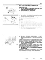
AIR CONDITIONING SYSTEM
PRECAUTION
1. DO NOT HANDLE REFRIGERANT IN AN ENCLOSED
AREA OR WEAR EYE PROTECTION
2. ALWAYS WEAR EYE PROTECTION
3. BE CAREFUL NOT TO GET LIQUID REFRIGERANT IN
YOUR EYES OR ON YOUR SKIN
If liquid refrigerant gets in your eyes or on your skin.
(a) Wash the area with lots of cool water.
CAUTION:
Do not rub your eyes or skin.
(b) Apply clean petroleum jelly to the skin.
(c) Go immediately to a physician or hospital for professional
treatment.
4. NEVER HEAT CONTAINER OR EXPOSE IT TO NAKED
FLAME
5. BE CAREFUL NOT TO DROP CONTAINER AND NOT
TO APPLY PHYSICAL SHOCKS TO IT
6. DO NOT OPERATE COMPRESSOR WITHOUT
ENOUGH REFRIGERANT IN REFRIGERATION SYS-
TEM
If there is not enough refrigerant in the refrigerant system oil lu-
brication will be insufficient and compressor burnout may occur,
so that care to avoid this, necessary care should be taken.
7. DO NOT OPEN PRESSURE MANIFOLD VALVE WHILE
COMPRESSOR IS OPERATE
If the high pressure valve is opened, refrigerant flows in the re-
verse direction and could cause the charging cylinder to rup-
ture, so open and close the only low pressure valve.
8. BE CAREFUL NOT TO OVERCHARGE SYSTEM WITH
REFRIGERANT
If refrigerant is overcharged, it causes problems such as insuffi-
cient cooling, poor fuel economy, engine overheating etc.
AC–2
–AIR CONDITIONING AIR CONDITIONING SYSTEM
2484AuthorĂ: DateĂ:
9. SUPPLEMENTAL RESTRAINT SYSTEM (SRS)
The CAMRY is equipped with an SRS (Supplemental Restraint
System) such as the driver airbag and passenger airbag. Fail-
ure to carry out service operations the correct sequence could
cause the SRS to unexpectedly deployed during servicing, pos-
sible the SRS may fail to operate when required. Before servic-
ing (including removal or installation of parts, inspection or re-
placement), be sure to read the following item carefully, then
follow the correct procedure described in the repair manual.
AC0LI–02
N20242
Sight Glass
–AIR CONDITIONING AIR CONDITIONING SYSTEM
AC–3
2485AuthorĂ: DateĂ:
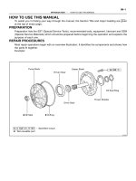
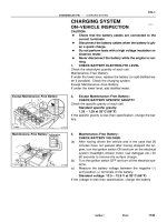
ON–VEHICLE INSPECTION
1. INSPECT REFRIGERANT VOLUME
Observe the sight glass on the liquid tube.
Test conditions:
z Running engine at 1,500 rpm
z Blower speed control switch at ”HI” position
z A/C switch ON
z Temperature control dial at ”COOL” position
z Fully open the doors
Item Symptom Amount of refrigerant Remedy
1 Bubbles present in sight glass Insufficient*
(1) Check for gas leakage with gas leak de-
tector and repair if necessary
(2) Add refrigerant until bubbles disappear
2 No bubbles present in sight glass None, sufficient or too much Refer item 3 and 4
3
No temperature difference between com-
pressor inlet and outlet
Empty or nearly empty
(1) Check for gas leakage with gas leak de-
tector and repair if necessary
(2) Add refrigerant until bubbles disappear
4
Temperature between compressor inlet and
outlet is noticeably different
Correct or too much Refer to items 5 and 6
5
Immediately after air conditioning is turned
off, refrigerant in sight glass stays clear
Too much
(1) Discharge refrigerant
(2) Evacuate air and charge proper amount
or purified refrigerant
6
When air conditioning is turned off, refriger-
ant foams and then stays clear
Correct –
*: Bubbles in the sight glass with ambient temperatures higher than usual can be considered normal if cooling
is sufficient.
I01386
AC–4
–AIR CONDITIONING AIR CONDITIONING SYSTEM
2486AuthorĂ: DateĂ:
2. INSPECT REFRIGERANT PRESSURE WITH MAN-
IFOLD GAUGE SET
This is a method in which the trouble is located by using a man-
ifold gauge set. Read the manifold gauge pressure when the
these conditions are established.
Test conditions:
z Temperature at the air inlet with the switch set
at RECIRC is 30 – 35 °C (86 – 95 °F)
z Engine running at 1500 rpm
z Blower speed control switch at ”HI” position
z Temperature control dial on ”COOL” position
HINT:
It should be noted that the gauge indications may vary slightly
due to ambient temperature conditions.
(1) Normally functioning refrigeration system.
Gauge reading:
Low pressure side:
0.15 – 0.25 MPa (1.5 – 2.5 kgf/cm
2
)
High pressure side:
1.37 – 1.57 MPa (14 – 16 kgf/cm
2)
I01387
Condition: Periodically cools and then fails to cool
I01388
Condition: Insufficient cooling
–AIR CONDITIONING AIR CONDITIONING SYSTEM
AC–5
2487AuthorĂ: DateĂ:
(2) Moisture present in refrigeration system.
Symptom seen in
refrigeration system
Probable cause Diagnosis Remedy
During operation, pressure on low
pressure side sometimes become
a vacuum and sometime normal
Moisture entered in refrigeration
system freezes at expansion valve
orifice and temporarily stops cycle,
but normal state is restored after a
time when the ice melts
z Drier oversaturated state
z Moisture in refrigeration system
freezes at expansion valve orifice
and blocks circulation of refriger-
ant
(1) Replace receiver
(2) Remove moisture in cycle
through repeatedly evacuating air
(3) Charge proper amount of new
refrigerant
(3) Insufficient cooling
Symptom seen in
refrigeration system
Probable cause Diagnosis Remedy
z Pressure low on both low and
high pressure sides
z Bubbles seen in sight glass con-
tinuously
z Insufficient cooling performance
Gas leakage at some place in re-
frigeration system
z Insufficient refrigerant in system
z Refrigerant leaking
(1) Check for gas leakage with gas
leak detector and repair if neces-
sary
(2) Charge proper amount of re-
frigerant
(3) If indicated pressure value is
near 0 when connected to gauge,
create the vacuum after inspecting
and repairing the location of the
leak
I01389
Condition: Insufficient cooling
I01449
Condition: Does not cool (Cools from time to time in some cases)
AC–6
–AIR CONDITIONING AIR CONDITIONING SYSTEM
2488AuthorĂ: DateĂ:
(4) Poor circulation of refrigerant
Symptom seen in
refrigeration system
Probable cause Diagnosis Remedy
z Pressure low in both low and
high pressure sides
z Frost on tube from receiver to
unit
Refrigerant flow obstructed by dirt
in receiver
Receiver clogged Replace receiver
(5) Refrigerant does not circulate
Symptom seen in
refrigeration system
Probable cause Diagnosis Remedy
z Vacuum indicated on low pres-
sure side, very low pressure indi-
cated on high pressure side
z Frost or dew seen on piping be-
fore and after receiver/ drier or ex-
pansion valve
z Refrigerant flow obstructed by
moisture or dirt in refrigeration sys-
tem
z Refrigerant flow obstructed by
gas leakage from expansion valve
Refrigerant does not circulate
(1) Check expansion valve
(2) Clean out dirt in expansion
valve by blowing with air
(3) Replace receiver
(4) Evacuate air and charge new
refrigerant to proper amount
(5) For gas leakage from expan-
sion valve, replace expansion
valve
I01390
Condition: Insufficient cooling
I01392
Condition: Insufficient cooling
NOTE : These gauge indica-
tions are shown when the
refrigeration system has
been opened and the refrig-
erant charged without vacu-
um purging.
–AIR CONDITIONING AIR CONDITIONING SYSTEM
AC–7
2489AuthorĂ: DateĂ:
(6) Refrigerant overcharged or insufficient cooling of
condenser
Symptom seen in
refrigeration system
Probable cause Diagnosis Remedy
z Pressure too high on both low
and high pressure sides
z No air bubbles seen through the
sight glass even when the engine
rpm is lowered
z Unable to develop sufficient per-
formance due to excessive refrig-
eration system
z Insufficient cooling of condenser
z Excessive refrigerant in
cycle → refrigerant over charged
z Condenser cooling → condenser
fins clogged of condenser fan
faulty
(1) Clean condenser
(2) Check condenser fan motor
operation
(3) If (1) and (2) are in normal
state, check amount of refrigerant
Charge proper amount of refriger-
ant
(7) Air present in refrigeration system
Symptom seen in
refrigeration system
Probable cause Diagnosis Remedy
z Pressure too high on both low
and high pressure sides
z The low pressure piping hot to
touch
z Bubbles seen in sight glass
Air entered in refrigeration system
z Air present in refrigeration sys-
tem
z Insufficient vacuum purging
(1) Check compressor oil to see if
it is dirty or insufficient
(2) Evacuate air and charge new
refrigerant
I01450
Condition: Insufficient cooling
I01393
Condition : Does not cool
AC–8
–AIR CONDITIONING AIR CONDITIONING SYSTEM
2490AuthorĂ: DateĂ:
(8) Expansion valve improperly
Symptom seen in
refrigeration system
Probable cause Diagnosis Remedy
z Pressure too high on both low
and high pressure sides
z Frost or large amount of dew on
piping on low pressure side
Trouble in expansion valve
z Excessive refrigerant in low
pressure piping
z Expansion valve opened too
wide
Check expansion valve
Replace if defective
(9) Defective compression compressor
Symptom seen in
refrigeration system
Probable cause Diagnosis Remedy
z Pressure too high on low and
high pressure sides
z Pressure too low on high pres-
sure side
Internal leak in compressor
z Compression defective
z Valve leaking or broken sliding
parts
Repair or replace compressor
–AIR CONDITIONING AIR CONDITIONING SYSTEM
AC–9
2491AuthorĂ: DateĂ:
3. INSPECT IDLE–UP SPEED
(a) Warm up engine.
(b) Inspect idle–up speed when the these conditions are es-
tablished.
z Warm up engine
z Blower speed control switch at ”HI” position
z A/C switch ON
z Temperature control dial at ”COOL” position
Magnetic clutch condition Idle–up speed
Magnetic clutch not engaged 700 ± 50 rpm
Magnetic clutch engaged 700 ± 50 rpm
If idle speed is not as specified, check ISC valve and air intake
system.
4. INSPECT FOR LEAKAGE OF REFRIGERANT
(a) Perform in these conditions:
z Stop engine.
z Secure good ventilation (If not the gas leak detector
may react to volatile gases witch are not refrigerant,
such as evaporated gasoline and exhaust gas.)
z Repeat the test 2 or 3 times.
z Make sure that there is some refrigerant remaining
in the refrigeration system.
When compressor is OFF: approx. 392 – 588 kPa
(4 – 6 kgf/ cm
2
, 57 – 85 psi)
(b) Bring the gas leak detector close to the drain hose before
performing the test.
HINT:
z After the blower motor stopped, leave the cooling unit for
more than 15 minutes.
z Expose the gas leak detector sensor the under the drain
hose.
z When bring the gas leak detector close to the drain hose,
make sure that the gas leak detector does not react to the
volatile gases.
If such reaction is unavoidable, the vehicle must be lifted up.
(c) If gas leak is not detected on the drain hose, remove the
blower resistor from the cooling unit. Then insert the gas
leak detector sensor into the unit and perform the test.
(d) Disconnect the connector and leave the pressure switch
for approx. 20 minutes. Then bring the gas leak detector
close to the pressure switch and perform the test.
(e) Bring the gas leak detector close to the refrigerant lines
and perform the test.
AC0LJ–03
N13795
Quick Disconnect
Adapter
Charging
Service Valve
Hose
N13794
Vacuum Pump
Vacuum Pump Adapter
N13791
Low Pressure
Service Valve
Vacuum Pump Adapter
High Pressure
Service Valve
Manifold
Gauge
Set
AC–10
–AIR CONDITIONING AIR CONDITIONING SYSTEM
2492AuthorĂ: DateĂ:
EVACUATING
1. CONNECT QUICK DISCONNECT ADAPTER TO
CHARGING HOSES
2. REMOVE CAPS FROM SERVICE VALVES ON RE-
FRIGERANT LINES
3. SET ON MANIFOLD GAUGE SET
(a) Close both hand valves of manifold gauge set.
(b) Connect the quick disconnect adapters to the service
valves.
4. EVACUATE AIR FROM REFRIGERATION SYSTEM
(a) Connect the vacuum pump adapter to the vacuum pump.
(b) Connect the center hose of the manifold gauge set to the
vacuum pump adapter.
(c) Open both the high and low hand valves and run the vacu-
um pump.
(d) After 10 minutes or more, check that the low pressure
gauge indicates 750 mmHg (30 in. Hg) or more.
HINT:
If the reading 750 mmHg (30 in. Hg) or more, close both hand
valves of manifold gauge set and stop the vacuum pump.
Check the system for leaks and repair necessary.
(e) Close both the high and low hand valves and stop the vac-
uum pump.
(f) Leave the system in this condition for 5 minutes or more
and check that there is no gauge indicator.
AC21S–01
N13793
Charging Cylinder
High Pressure
Service Valve
Low Pressure
Service Valve
Push
Air
N13792
Gas Leak
Detector
–AIR CONDITIONING AIR CONDITIONING SYSTEM
AC–11
2493AuthorĂ: DateĂ:
CHARGING
1. INSTALL CHARGING CYLINDER
HINT:
When handling the charging cylinder, always follow the direc-
tions given in the instruction manual.
(a) Charge the proper amount of refrigerant into the charging
cylinder.
(b) Connect the center hose to the charging cylinder.
CAUTION:
Do not open both high and low hand valves of manifold
gauge set.
(c) Open the valve of charging cylinder.
(d) Press the valve core on the side of manifold gauge and
expel the air inside of the center hose.
2. INSPECT REFRIGERATION SYSTEM FOR LEAKS
(a) Open the high pressure hand valve and charge refriger-
ant.
(b) When the low pressure gauge indicates 98 kPa
(1 kgf/cm
2
, 14 psi) close the high pressure hand valve.
(c) Using a gas leak detector, check the system for leakage.
(d) If leak is found, repair the faulty component or connection.
CAUTION:
Use the refrigerant recovery/ recycling machine to recover
the refrigerant whenever replacing parts.
N13790
Low Pressure
Service Valve
High Pressure
Service Valve
I07055
Properly
Charged
Insufficiently
Charged
AC–12
–AIR CONDITIONING AIR CONDITIONING SYSTEM
2494AuthorĂ: DateĂ:
3. CHARGE REFRIGERANT INTO REFRIGERANT SYS-
TEM
If there is no leak after refrigerant leak check, charge the proper
amount of refrigerant into refrigeration system.
CAUTION:
z Never run the engine when charging the system
through the high pressure side.
z Do not open the low pressure hand valve when the
system is being charged with liquid refrigerant.
(a) Open the high pressure hand valve fully.
(b) Charge specified amount of refrigerant, then close the
high pressure hand valve.
HINT:
A fully charged system is indicated by the sight glass being free
of any bubbles.
(c) Charge partially refrigeration system with refrigerant.
(1) Set vehicle in these conditions:
z Running engine at 1,500 rpm
z Blower speed control set at ”HI”
z Temperature control set at ”MAX. COOL”
z Air inlet control set at ”RECIRC”
z Fully open doors (Sliding roof: closed)
(2) Open the low pressure hand valve.
CAUTION:
Do not open the high pressure hand valve.
(d) Charge refrigerant until bubbles disappear and check the
pressure on the gauge through the sight glass.
AC0LL–02
Z19146
1MZ–FE engine:
No. 1 Engine Coolant Temperature
(ECT) Switch
Compressor
Engine Room Junction Block No. 2
z Engine Main Relay
(Marking: ENGINE MAIN)
z No. 1 Cooling Fan Relay
(Marking: FAN NO.1)
Engine Room Relay Block No. 1
z Magnetic Clutch Relay
(Marking: MG CLT)
z Heater Main Relay
(Marking: HTR)
z No. 2 Cooling Fan Relay
(Marking: FAN NO.2)
z No. 3 Cooling Fan Relay
(Marking: FAN NO.3)
5S–FE engine models:
Engine Coolant Temperature
(ECT) Switch
Receiver
Pressure Switch
Condenser Fan
z Fan Motor
1MZ–FE engine:
No. 2 Engine Coolant Temperature
(ECT) Switch
Condenser
Blower Unit
A/C Unit
A/C Control Assembly
z A/C Switch
z Blower Speed Control Switch
z Mode Switch
Air Outlet Servomotor
Heater Radiator
Thermistor
Blower Resistor
Blower Motor
1MZ–FE:
A/C Amplifier
Expansion Valve
5S–FE engine:
ECM (Built in A/C Amplifier)
Evaporator
–AIR CONDITIONING AIR CONDITIONING SYSTEM
AC–13
2495AuthorĂ: DateĂ:
LOCATION
AC21T–01
AC–14
–AIR CONDITIONING TROUBLESHOOTING
2496AuthorĂ: DateĂ:
TROUBLESHOOTING
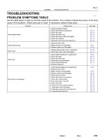
PROBLEM SYMPTOMS TABLE
Use the table below to help you find the cause of the problem. The numbers indicate the priority of the likely
cause of the problem. Check each part in order. If necessary, replace these parts.
Symptom Suspect Area See page
No blower operation
4. HTR Fuse
5. Heater main relay
6. Blower motor
7. Blower resistor
8. Blower speed control switch
9. Wire harness
–
AC–70
AC–63
AC–64
AC–84
–
No air temperature control
1. Engine coolant volume
2. A/C control assembly
–
AC–80
No air inlet control 1. A/C control assembly AC–80
No air outlet control
1. HTR Fuse
2. Air outlet servomotor
3. Mode switch
–
AC–65
AC–84
No compressor operation
1. Refrigerant volume
2. A.C Fuse
3. HTR Fuse
4. Magnetic clutch relay
5. Magnetic clutch
6. Compressor
7. Pressure switch
8. Heater main relay
9. Blower speed control switch
10.A/C switch
11.*1 ECM
*
2
A/C amplifier
12.Wire harness
AC–3
–
–
AC–71
AC–39
AC–39
AC–67
AC–70
AC–84
AC–84
DI–218
AC–88
–
No compressor operates intermittently
1. Refrigerant volume
2. Condenser fan
3. Pressure switch
4. *1 ECM
*2 A/C amplifier
5. Thermistor
6. Wire harness
AC–3
AC–74
AC–67
DI–218
AC–88
AC–24
–
No cool air comes out
1. Refrigerant volume
2. Refrigerant pressure
3. Drive belt
4. Compressor lock sensor
5. Magnetic clutch
6. Compressor
7. Pressure switch
8. Thermistor
9. A/C switch
10.*1 ECM
*2 A/C amplifier
11.Wire harness
AC–3
AC–3
AC–16
AC–16
AC–39
AC–39
AC–67
AC–24
AC–84
DI–218
AC–88
–
–AIR CONDITIONING TROUBLESHOOTING
AC–15
2497AuthorĂ: DateĂ:
Cool air comes out only at high engine rpm
1. Refrigerant volume
2. Drive belt
3. Magnetic clutch
4. Compressor
5. Condenser
6. Condenser fan
7. Receiver
8. Expansion valve
9. Evaporator
10.Thermistor
11.Refrigerant line
12.Pressure switch
13.*
1
ECM
*
2
A/C amplifier
AC–3
AC–16
AC–16
AC–39
AC–52
AC–74
AC–49
AC–59
AC–30
AC–24
AC–21
AC–67
DI–218
AC–88
No engine idle–up when A/C switch ON
1. *
1
ECM
*
2
A/C amplifier
2. Wire harness
DI–218
AC–88
–
Blinking of A/C indicator
1. *
1
ECM
*
2
A/C amplifier
2. Thermistor
3. Compressor
DI–218
AC–88
AC–24
AC–39
A/C indicator does not lights up when turn mode switch to DEF.
position
1. A/C Fuse
2. Mode switch
3. A/C switch
4. *
1
ECM
*
2
A/C amplifier
5. Wire harness
–
AC–84
AC–84
DI–218
AC–88
–
No warm air comes out
1. Engine coolant volume
2. A/C control assembly
3. Heater radiator
–
AC–80
AC–57
No condenser fan operation
1. CDS FAN Fuse
2. Engine main relay
3. Cooling fan relay No. 1
4. Cooling fan relay No. 2
5. Cooling fan relay No. 3
6. Condenser fan motor
7. Pressure switch
8. *
1
Engine coolant temp. switch
*
2
No. 1 Engine coolant temp. switch
9. *
2
No. 2 Engine coolant temp. switch
10.Wire harness
–
–
AC–72
AC–72
AC–72
AC–74
AC–67
AC–92
AC–92
AC–92
–
*
1
: 5S–FE Engine Models
*
2
: 1MZ–FE Engine Models
CH0086
Correct Wrong
AC0LM–02
N17028
Generator
Crankshaft Pulley
Compressor
N01881
DENSO
Borroughs
AC–16
–AIR CONDITIONING DRIVE BELT
2498AuthorĂ: DateĂ:
DRIVE BELT
ON–VEHICLE INSPECTION
1. INSPECT DRIVE BELT’S INSTALLATION CONDITION
Check that the drive belt fits properly in the ribbed grooves.
2. INSPECT DRIVE BELT TENSION
Using a belt tension gauge, check the drive belt tension.
Drive belt tension:
New belt: 165 ± 26 lbf
Used belt: 110 ± 11 lbf
HINT:
z ”New belt” refers to a belt which has been used less than
5 minutes on a running engine.
z ”Used belt” refers to a belt which has been used on a run-
ning engine for 5 minutes or more.
z After installing the drive belt, check that it fits properly in
the ribbed grooves.
AC0LN–02
Z19189
Pivot Bolt
Adjusting Bolt
Drive Belt
Pivot Bolt
Drive Belt
Adjusting Lock
Bolt
Adjusting Bolt
5S–FE:
1MZ–FE:
Adjusting Lock
Bolt
–AIR CONDITIONING DRIVE BELT
AC–17
2499AuthorĂ: DateĂ:
REMOVAL
REMOVE DRIVE BELT
(a) Loosen the pivot bolt and adjusting lock bolt.
Torque:
5S–FE:
Pivot bolt: 52 N·m (530 kgf·cm, 38 ft·lbf)
Adjusting lock bolt: 18 N·m (185 kgf·cm, 13 ft·lbf)
1MZ–FE:
Pivot bolt: 56 N·m (570 kgf·cm, 41 ft·lbf)
Adjusting lock bolt: 18 N·m (185 kgf·cm, 13 ft·lbf)
(b) Loosen the drive belt tension by adjusting bolt and re-
move the drive belt.
AC0LO–01
AC–18
–AIR CONDITIONING DRIVE BELT
2500AuthorĂ: DateĂ:
INSTALLATION
Installation is in the reverse order of removal (See page AC–17).
N20312
High Pressure
Charging hose
Low Pressure
Charging Hose
AC0LP–02
N04392
Sleeve
–AIR CONDITIONING MANIFOLD GAUGE SET
AC–19
2501AuthorĂ: DateĂ:
MANIFOLD GAUGE SET
SET ON
1. CONNECT CHARGING HOSES TO MANIFOLD
GAUGE SET
Tighten the nuts by hand.
CAUTION:
Do not connect the wrong hoses.
2. CONNECT QUICK DISCONNECT ADAPTERS TO
CHARGING HOSES
Tighten the nuts by hand.
3. CLOSE BOTH HAND VALVES OF MANIFOLD GAUGE
SET
4. REMOVE CAPS FROM SERVICE VALVES ON RE-
FRIGERANT LINE
5. CONNECT QUICK DISCONNECT ADAPTERS TO SER-
VICE VALVES
HINT:
Push the quick disconnect adapter onto the service valve, then
slide the sleeve of the quick disconnect adapter downward to
lock it.
AC0LQ–02
N06553
AC–20
–AIR CONDITIONING MANIFOLD GAUGE SET
2502AuthorĂ: DateĂ:
SET OFF
1. CLOSE BOTH HAND VALVES OF MANIFOLD GAUGE
SET
2. DISCONNECT QUICK DISCONNECT ADAPTERS
FROM SERVICE VALVES ON REFRIGERANT LINE
HINT:
Slide the sleeve of the quick disconnect adapter upward to un-
lock the adapter and remove it from the service valve.
3. INSTALL CAPS TO SERVICE VALVES ON REFRIGER-
ANT LINE
AC0LR–01
–AIR CONDITIONING REFRIGERANT LINE
AC–21
2503A uthorĂ: DateĂ:
REFRIGERANT LINE
ON–VEHICLE INSPECTION
1. INSPECTION HOSE AND TUBE CONNECTIONS FOR LOOSENESS
2. INSPECT HOSES AND TUBES FOR LEAKAGE
Using a gas leak detector, check for leakage of refrigerant.
AC0LS–02
I07049
Suction Tube
Liquid Tube
Piping Clamp
Liquid Tube
Suction Hose
Discharge Hose
N·m (kgf·cm, ft·lbf) : Specified torque
32 (330, 24)
5.4 (55, 48 in.·lbf)
5.4 (55, 48 in.·lbf)
10 (100, 7)
10 (100, 7)
10 (100, 7)
14 (140, 10)
5.4 (55, 48 in.·lbf)
AC–22
–AIR CONDITIONING REFRIGERANT LINE
2504A uthorĂ: DateĂ:
LOCATION
AC0LT–03
–AIR CONDITIONING REFRIGERANT LINE
AC–23
2505A uthorĂ: DateĂ:
REPLACEMENT
1. DISCHARGE REFRIGERANT FROM REFRIGERATION SYSTEM
2. REPLACE FAULTY TUBE OR HOSE
NOTICE:
Cap the open fittings immediately to keep moisture or dirt out of the system.
3. TIGHTEN JOINT OF BOLT OR NUT TO SPECIFIED TORQUE
NOTICE:
Connections should not be torqued tighter than the specified torque.
Part tightened N·m kgf·cm ft·lbf
Receiver x Liquid tube 5.4 55 48 in.·lbf
Condenser x Discharge hose 10 100 7
Condenser x Liquid tube 14 140 10
Compressor x Discharge hose 10 100 7
Compressor x Suction hose 10 100 7
Expansion valve x Evaporator 5.4 55 48 in.·lbf
Suction line (Piping joint) 32 330 24
Suction line (Block joint) 10 100 7
4. EVACUATE AIR FROM REFRIGERATION SYSTEM AND CHARGE WITH REFRIGERANT
Specified amount : 800 ± 50g (28.22 ± 1.76 oz.)
5. INSPECT FOR LEAKAGE OF REFRIGERANT
Using a gas leak detector, check for leakage of refrigerant.
6. INSPECT AIR CONDITIONING OPERATION
AC21U–01
N20296
N20294
AC–24
–AIR CONDITIONING AIR CONDITIONING UNIT
2506AuthorĂ: DateĂ:
AIR CONDITIONING UNIT
ON–VEHICLE INSPECTION
1. INSPECT FOR LEAKAGE OF REFRIGERANT
(a) Remove glove compartment (See page BO–75).
(b) Remove the blower resistor.
(1) Disconnect the connector.
(2) Remove the 2 screws and blower resistor.
(c) Using a gas leak detector, check for leakage.
If there is leakage, check the tightening torque at the joints or
check the evaporator.
(d) Install the blower resistor.
(e) Install the lower No. 2 finish panel (See page BO–81).
2. INSPECT THERMISTOR RESISTANCE
(a) Disconnect the connector.
(b) Measure resistance between terminals.
Standard resistance: 1,500 Ω at 25°C (77°F)
If resistance is not as specified, replace the thermistor.
AC21V–01
I07050
Reinforcement
Instrument Panel
No. 1 Brace
No. 2 Brace
A/C Unit
Piping Clamp
Suction Tube
Liquid Tube
Piping Clamp
z O–ring
z O–ring
Air Duct (Rear Foot)
Air Duct (Foot)
Blower Motor
Connector Bracket
z Non–reusable part
Water Hose
–AIR CONDITIONING AIR CONDITIONING UNIT
AC–25
2507AuthorĂ: DateĂ:
COMPONENTS