Tiêu chuẩn iso 00005 1 2009
Bạn đang xem bản rút gọn của tài liệu. Xem và tải ngay bản đầy đủ của tài liệu tại đây (249.07 KB, 24 trang )
ISO
5-1
INTERNATIONAL
STANDARD
Second edition
2009-12-01
Photography and graphic technology —
Density measurements —
Part 1:
Geometry and functional notation
Photographie et technologie graphique — Mesurages de la densité —
Partie 1: Géométrie et notation fonctionnelle
--`,,```,,,,````-`-`,,`,,`,`,,`---
Reference number
ISO 5-1:2009(E)
Copyright International Organization for Standardization
Provided by IHS under license with ISO
No reproduction or networking permitted without license from IHS
© ISO 2009
Not for Resale
ISO 5-1:2009(E)
PDF disclaimer
This PDF file may contain embedded typefaces. In accordance with Adobe's licensing policy, this file may be printed or viewed but
shall not be edited unless the typefaces which are embedded are licensed to and installed on the computer performing the editing. In
downloading this file, parties accept therein the responsibility of not infringing Adobe's licensing policy. The ISO Central Secretariat
accepts no liability in this area.
Adobe is a trademark of Adobe Systems Incorporated.
COPYRIGHT PROTECTED DOCUMENT
© ISO 2009
All rights reserved. Unless otherwise specified, no part of this publication may be reproduced or utilized in any form or by any means,
electronic or mechanical, including photocopying and microfilm, without permission in writing from either ISO at the address below or
ISO's member body in the country of the requester.
ISO copyright office
Case postale 56 • CH-1211 Geneva 20
Tel. + 41 22 749 01 11
Fax + 41 22 749 09 47
Web www.iso.org
Published in Switzerland
ii
Copyright International Organization for Standardization
Provided by IHS under license with ISO
No reproduction or networking permitted without license from IHS
© ISO 2009 – All rights reserved
Not for Resale
--`,,```,,,,````-`-`,,`,,`,`,,`---
Details of the software products used to create this PDF file can be found in the General Info relative to the file; the PDF-creation
parameters were optimized for printing. Every care has been taken to ensure that the file is suitable for use by ISO member bodies. In
the unlikely event that a problem relating to it is found, please inform the Central Secretariat at the address given below.
ISO 5-1:2009(E)
Contents
Page
Foreword ............................................................................................................................................................iv
Introduction.........................................................................................................................................................v
1
Scope ......................................................................................................................................................1
2
Normative references............................................................................................................................1
3
Terms and definitions ...........................................................................................................................1
4
Equations ...............................................................................................................................................4
5
Instrument representation ....................................................................................................................5
6
Coordinate system ................................................................................................................................6
7
Description of geometry .......................................................................................................................7
8
8.1
8.2
8.3
8.4
Functional notation ...............................................................................................................................8
General ...................................................................................................................................................8
Geometric conditions............................................................................................................................8
Spectral conditions .............................................................................................................................11
Examples of functional notation........................................................................................................12
Annex A (informative) Terms and definitions used in other parts of ISO 5 ................................................13
Bibliography......................................................................................................................................................16
--`,,```,,,,````-`-`,,`,,`,`,,`---
iii
© ISO 2009 – All rights reserved
Copyright International Organization for Standardization
Provided by IHS under license with ISO
No reproduction or networking permitted without license from IHS
Not for Resale
ISO 5-1:2009(E)
Foreword
ISO (the International Organization for Standardization) is a worldwide federation of national standards bodies
(ISO member bodies). The work of preparing International Standards is normally carried out through ISO
technical committees. Each member body interested in a subject for which a technical committee has been
established has the right to be represented on that committee. International organizations, governmental and
non-governmental, in liaison with ISO, also take part in the work. ISO collaborates closely with the
International Electrotechnical Commission (IEC) on all matters of electrotechnical standardization.
International Standards are drafted in accordance with the rules given in the ISO/IEC Directives, Part 2.
Attention is drawn to the possibility that some of the elements of this document may be the subject of patent
rights. ISO shall not be held responsible for identifying any or all such patent rights.
ISO 5-1 was prepared by ISO/TC 42, Photography, and ISO/TC 130, Graphic technology, in a Joint Working
Group.
This second edition cancels and replaces the first edition (ISO 5-1:1984), which has been technically revised.
In the course of this technical revision, all parts of ISO 5 have been reviewed together, and the terminology,
nomenclature and technical requirements have been made consistent across all parts.
ISO 5 consists of the following parts, under the general title Photography and graphic technology — Density
measurements:
⎯
Part 1: Geometry and functional notation
⎯
Part 2: Geometric conditions for transmittance density
⎯
Part 3: Spectral conditions
⎯
Part 4: Geometric conditions for reflection density
iv
Copyright International Organization for Standardization
Provided by IHS under license with ISO
No reproduction or networking permitted without license from IHS
© ISO 2009 – All rights reserved
Not for Resale
--`,,```,,,,````-`-`,,`,,`,`,,`---
The main task of technical committees is to prepare International Standards. Draft International Standards
adopted by the technical committees are circulated to the member bodies for voting. Publication as an
International Standard requires approval by at least 75 % of the member bodies casting a vote.
ISO 5-1:2009(E)
Introduction
The measurement of the transmission and reflection characteristics of objects is essential to the science of
photography and graphic arts. When light, or other radiant energy, is incident upon an object, it is either
absorbed or propagated. Propagation can involve reflection, transmission, refraction, diffraction, scattering,
fluorescence, and polarization. The propagated light is distributed in various directions about the object. In
most practical applications it is neither necessary nor desirable to consider the light distributed in every
direction, but only that which leaves the object in the direction for which there is response by a receiver, such
as the eye.
The object modulates the flow of radiant energy from the illuminator to the receiver. The time rate of flow of
radiant energy is called radiant flux, or simply flux. This part of ISO 5 provides methods to describe the
measurements of the flux modulation in any system. To specify such a system accurately, geometric
characteristics of the system, the spectral distribution of the flux incident on the object to be measured, and
the spectral responsivity of the receiver need to be given. If the reflection characteristics of the illuminator or
receiver affect the measurement, as they do in transmission measurements by the opal glass method, they
need to be specified.
The area under consideration is defined by a sampling aperture, the dimensions of which can be important in
some applications and need to be specified if the object has appreciable non-uniformity. If the measurement is
to quantify the way the object would modulate flux in a given practical application, such as viewing or contact
printing, the geometric and spectral conditions of measurement need to simulate those conditions in the
practical application.
--`,,```,,,,````-`-`,,`,,`,`,,`---
Modulation is measured and expressed as a dimensionless ratio of fluxes; that is, the flux propagated in the
direction of the receiver and that part of the spectrum of interest divided by some reference flux. The reference
flux can be the incident flux or the flux propagated through the system when the object is replaced by an ideal
object. For some purposes, a logarithmically scaled measure of modulation is more useful than the measured
arithmetic ratio. In such cases, it is customary to use optical density defined as the negative logarithm to base
10 of the ratio.
Most geometric arrangements used in photographic and graphic arts optical systems can be conveniently and
adequately described in terms of uniform rays of flux bounded by right circular cones. A point on the object is
often illuminated by such a conic distribution, and the geometric form of the pencil of rays reaching the
receiver is generally conic. The pupil of the eye, for example, subtends a conic solid angle at an object point.
In projection systems, the projection lens subtends a conic solid angle at the specimen point. This part of
ISO 5 specifies a conic distribution by the half-angle of the cone and the direction of its axis.
A working knowledge of radiometry is generally required to obtain primary standard measurements of
transmittance and reflectance. In good radiometric practice, for example, the effects of stray light are
minimized by the use of appropriate baffles and proper blackening of certain surfaces. Because the principles
and practice of radiometry are well known and are fully described in the Handbook of Applied Photometry [ 1 0 ] ,
it is considered unnecessary to provide a detailed specification of radiometric procedures in this part of ISO 5.
v
© ISO 2009 – All rights reserved
Copyright International Organization for Standardization
Provided by IHS under license with ISO
No reproduction or networking permitted without license from IHS
Not for Resale
--`,,```,,,,````-`-`,,`,,`,`,,`---
Copyright International Organization for Standardization
Provided by IHS under license with ISO
No reproduction or networking permitted without license from IHS
Not for Resale
INTERNATIONAL STANDARD
ISO 5-1:2009(E)
Photography and graphic technology — Density
measurements —
Part 1:
Geometry and functional notation
1
Scope
This part of ISO 5 establishes terms, symbols, functional notations and a coordinate system to describe
geometric and spectral conditions for the measurement of the degree to which a specimen modulates radiant
flux for applications in photography, graphic technology, and radiometry.
This part of ISO 5 primarily provides a system for describing methods of measuring or specifying the
transmission and reflection properties of photographic and graphic arts materials. The geometric and spectral
conditions associated with such measurement are specified in ISO 5-2, ISO 5-3 and ISO 5-4.
2
Normative references
The following referenced documents are indispensable for the application of this document. For dated
references, only the edition cited applies. For undated references, the latest edition of the referenced
document (including any amendments) applies.
ISO 5-2, Photography and graphic technology — Density measurements — Part 2: Geometric conditions for
transmittance density
ISO 5-3, Photography and graphic technology — Density measurements — Part 3: Spectral conditions
ISO 5-4, Photography and graphic technology — Density measurements — Part 4: Geometric conditions for
reflection density
3
Terms and definitions
For the purposes of this document, the following terms and definitions apply1).
3.1
absolute reference reflected flux
ΦrA
radiant flux that would be reflected by a perfect reflecting diffuser
1) For the convenience of the user, Annex A lists those terms and definitions used in other parts of ISO 5 that are not
used in this part of ISO 5.
1
--`,,```,,,,````-`-`,,`,,`,`,,`---
© ISO 2009 – All rights reserved
Copyright International Organization for Standardization
Provided by IHS under license with ISO
No reproduction or networking permitted without license from IHS
Not for Resale
ISO 5-1:2009(E)
3.2
absolute reference transmitted flux
ΦtA
radiant flux that would be transmitted by a perfect transmitting diffuser
3.3
anormal angle
θ
angle between the normal of the reference plane and a direction
NOTE
Adapted from ASTM E1767.
3.4
azimuthal angle
η
angle between the x-axis of the reference plane and the projection of a direction onto the reference plane
NOTE
Adapted from ASTM E284.
3.5
cone half-angle
κ
angle between the central axis and the edge of the pupil with the apex at the centre of the sampling aperture
3.6
efflux
radiant flux collected by the receiver from the reference plane
NOTE
Adapted from ASTM E1767.
3.7
illuminator axis
central axis of the illuminator, usually the optical axis
3.8
illuminator region
intersection of the illuminator beam with the reference plane
3.9
incident flux
Φi
radiant flux incident upon the sampling aperture
3.10
influx
radiant flux projected by the illuminator onto the reference plane
NOTE
Adapted from ASTM E1767.
3.11
influx spectrum
S
spectral distribution of the radiometric quantity, such as radiance, irradiance or radiant flux, incident upon the
sampling aperture
NOTE
This is a function of the source and optics used for the illumination.
--`,,```,,,,````-`-`,,`,,`,`,,`---
2
Copyright International
Organization for Standardization
Provided by IHS under license with ISO
No reproduction or networking permitted without license from IHS
© ISO 2009 – All rights reserved
Not for Resale
ISO 5-1:2009(E)
3.12
ISO 5 standard density
density value obtained using an instrument conforming to one of the geometries specified in ISO 5-2 or
ISO 5-4, and one of the spectral definitions in ISO 5-3
3.13
receiver axis
central axis of the receiver, usually the optical axis
3.14
receiver region
intersection of the receiver beam with the reference plane
3.15
reflectance
ρ
ratio of the reflected flux to the incident flux under specified geometrical and spectral conditions of
measurement
NOTE
Adapted from ASTM E284.
3.16
reflectance density
Dρ
negative logarithm to the base 10 of the reflectance
3.17
reflectance factor
R
ratio of the reflected flux to the absolute reference reflected flux under the same geometrical and spectral
conditions of measurement
3.18
reflected flux
Φr
radiant flux that emerges from the specimen surface on which the incident flux falls
3.19
reflection density
DR
negative logarithm to the base 10 of the reflectance factor
NOTE
The International Commission on Illumination (CIE) designates the measurement referred to as “reflection
density” in ISO 5 as “reflectance factor density”. (See IEC 60050-845:1987⏐CIE 17.4:1987.)
3.20
spectral responsivity
s
output signal of a receiver per unit input of radiant flux as a function of wavelength
NOTE
Adapted from ASTM E284.
3.21
transmission density
DT
negative logarithm to the base 10 of the transmittance factor
--`,,```,,,,````-`-`,,`,,`,`,,`---
© ISO 2009 – All rights reserved
Copyright International Organization for Standardization
Provided by IHS under license with ISO
No reproduction or networking permitted without license from IHS
Not for Resale
3
ISO 5-1:2009(E)
3.22
transmittance
τ
ratio of the transmitted flux to the incident flux under specified geometrical and spectral conditions of
measurement
NOTE 1
In practical instruments for transmittance measurements, the incident flux is defined by the combination of all
of the components that are placed before the reference plane (influx), so the incident flux is provided by the surface of the
opal diffuser for diffuse transmittance and by the film gate for projection density.
NOTE 2
Adapted from ASTM E284.
3.23
transmittance density
Dτ
negative logarithm to the base 10 of the transmittance
NOTE
The subscript is the lower case Greek letter tau.
3.24
transmittance factor
T
ratio of the transmitted flux to the absolute reference transmitted flux under the same geometrical and spectral
conditions of measurement
NOTE
Adapted from ASTM E284.
3.25
transmitted flux
Φt
radiant flux that passes through the specimen and emerges from a surface other than that on which the
incident flux falls
4
Equations
The terms and equations applicable to density measurements are given in Table 1.
Table 1 — Terms and equations for density measurements
Term
Equation
Term
Equation
Transmittance
τ =
Φt
Φi
Transmittance density
Dτ = − log 10 τ
Reflectance
ρ=
Φr
Φi
Reflectance density
D ρ = − log 10 ρ
Transmittance factor
T =
Φt
Φ tA
Transmission density
D T = − log 10 T
Reflectance factor
R=
Φr
Φ rA
Reflection density
D R = − log 10 R
--`,,```,,,,````-`-`,,`,,`,`,,`---
4
Copyright International
Organization for Standardization
Provided by IHS under license with ISO
No reproduction or networking permitted without license from IHS
© ISO 2009 – All rights reserved
Not for Resale
ISO 5-1:2009(E)
5
Instrument representation
Every instrument used to perform optical density measurements of a specimen typically has three
components:
⎯
an illuminator to project radiant flux onto the specimen,
⎯
a reference plane at which the specimen is placed, and
⎯
a receiver to measure the radiant flux from the specimen.
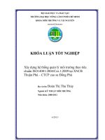
These components are shown schematically in Figure 1 for a general instrument. The illuminator consists of a
source for providing radiant flux, and a director, which directs the radiant flux from the source onto the
reference plane. Likewise, the receiver consists of a collector, which guides the radiant flux from the reference
plane to the detector, which is a device that converts radiant flux into a measurable signal. Examples of
sources are incandescent and arc lamps, while examples of detectors are photodiodes and photomultiplier
tubes. The central axes, marginal rays, and chief rays of the illuminator and receiver are also shown in
Figure 1 as dashed, thin, and thick lines, respectively.
The illuminator and receiver are optical systems with aperture and field stops. These stops determine the
illuminator and receiver beams, which are the collections of rays that can pass through the systems. The
images of the aperture stops as viewed from the reference plane are the pupils. The illuminator axis is the
central axis of the illuminator beam, and is usually the optical axis of the illuminator, although it could also be
the centroid of the distribution of rays within the beam. The illuminator axis has an angle of illumination with
respect to the normal of the reference plane. Likewise, the receiver axis is the central axis of the receiver
beam and has an angle of observation (or viewing) with respect to the normal of the reference plane. The
intersections of the illuminator and receiver beams with the reference plane are the illuminator and receiver
regions, respectively.
Key
1
director
2
3
source
illuminator
4
5
receiver
detector
6
7
collector
reference plane
Figure 1 — A schematic representation of the three components of an instrument used for
densitometry (illuminator, reference plane, and receiver) and their parts
--`,,```,,,,````-`-`,,`,,`,`,,`---
5
© ISO 2009 – All rights reserved
Copyright International Organization for Standardization
Provided by IHS under license with ISO
No reproduction or networking permitted without license from IHS
Not for Resale
ISO 5-1:2009(E)
The geometrical and spectral properties of the illuminator determine the influx, which is the radiant flux
projected by the illuminator onto the reference plane. The efflux is the radiant flux collected by the receiver
from the reference plane. The incident flux is the influx on the sampling aperture, while the reflected or
transmitted flux is the efflux from the sampling aperture detected by the receiver. If the sampling aperture is
determined by the illuminator region, then the incident flux is equivalent to the influx, and the reflected or
transmitted flux is equivalent to the efflux. However, if the sampling aperture is determined by the receiver
region, then the incident flux is not equivalent to the influx, although the equivalence of the efflux to the
reflected or transmitted flux is unchanged.
6
Coordinate system
Since the components of the instrument are fixed in space, they define the coordinate system for the
measurement. The coordinate system for describing the geometric factors affecting optical transmission and
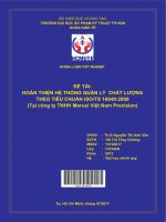
reflection measurements is given in Figure 2. The xy-plane is the reference plane, which is the plane in which
the front surface of the specimen is placed for measurement. The origin of the reference plane (O) is the
centre of the sampling aperture. The z-axis is perpendicular to the reference plane.
An arbitrary direction and its projection on the reference plane are also given in Figure 2, with anormal angle,
θ, and azimuthal angle, η. The anormal angle of incident and reflected rays shall be measured from the
negative z-axis, while the anormal angle of transmitted rays shall be measured from the positive z-axis. The
azimuthal angle of a ray is the angle in the xy-plane from the positive x-axis in the direction of the positive
y-axis to the projection of the ray on the xy-plane. A direction is specified by the coordinates θ and η, in that
order. Angle η is less than 360°, and angle θ is less than or equal to 180° (and usually less than or equal to
90°).
Subscripts for the directional angles of rays correspond to the subscripts for fluxes, i.e.
⎯
“i” for incident;
⎯
“r” for reflected;
⎯
“t” for transmitted.
EXAMPLE
θ i; η r; θ t.
If the thickness of the specimen needs to be considered, then the description of the efflux distribution may be
referred to a secondary coordinate system (x′, y′, z′, θ ′, η ′) having its origin (O) displaced a specified distance,
h, corresponding to the thickness along the positive z-axis, such that x′ = x, y′ = y, z′ = z − h; the angles are
defined in a corresponding manner.
In a system in which the sampling aperture moves relative to the specimen, the standard direction of motion of
the aperture shall be in the direction of the positive x-axis. Such a sampling aperture is called a “scanning
aperture”.
6
Copyright International Organization for Standardization
Provided by IHS under license with ISO
No reproduction or networking permitted without license from IHS
© ISO 2009 – All rights reserved
Not for Resale
--`,,```,,,,````-`-`,,`,,`,`,,`---
The sampling aperture is the intersection of the illuminator and receiver regions. These two regions are
typically centred at the same location on the reference plane, so the smaller of the two is the sampling
aperture. The sampling aperture is the area of the specimen selected for measurement.
ISO 5-1:2009(E)
Key
1
2
origin (O)
z-component of incident flux
Figure 2 — Coordinate system for describing the geometric factors affecting transmission
and reflection measurements
7
Description of geometry
The description of the geometry starts with the type of geometry, which applies to both the illuminator and
receiver and depends upon their axes. The types of geometry are
⎯
directional,
⎯
annular, and
⎯
hemispherical.
For the directional geometry, the axis has one fixed anormal angle and one fixed azimuthal angle. For the
annular geometry, the axis has one fixed anormal angle and all azimuthal angles. For the hemispherical
geometry, there is no defined axis. Specific cases of the directional geometry are the circumferential
geometry, in which there are more than one discrete fixed azimuthal angles, and the uniplanar geometry, in
which the illuminator and receiver axes and the normal to the reference plane are in the same plane.
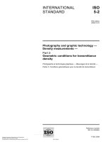
In many cases, the illuminator and receiver beams can be adequately described in terms of cones. Figure 3
(which is an extension of Figure 2) shows the coordinate system and necessary conventions. The half-angle
of a beam is designated κ (using subscripts “i” for incident, “r” for reflected, and “t” for transmitted) and it is the
angle from the central axis of the beam to the edge with apex at the centre of the sampling aperture. For the
directional geometry, the half-angle is rotationally symmetric about the axis. For the annular geometry, the
half-angle is confined to the anormal direction. For the hemispherical geometry, there is no half-angle.
--`,,```,,,,````-`-`,,`,,`,`,,`---
7
© ISO 2009 – All rights reserved
Copyright International Organization for Standardization
Provided by IHS under license with ISO
No reproduction or networking permitted without license from IHS
Not for Resale
ISO 5-1:2009(E)
Figure 3 — Coordinate system and angular conventions for describing distributions in terms of cones
8
Functional notation
8.1
General
Functional notation provides a means of denoting the measured quantity, Y, and the parameters on which it
depends. The symbol for the quantity is followed by the symbols for the various parameters (or their values in
a specific case) in parentheses as:
Y(G; S: g; s)
where
G
is the illuminator geometry;
S
is the spectral power distribution of the influx;
g
is the receiver geometry;
s
is the spectral responsivity of the receiver.
The illuminator and receiver functions are separated by a colon. The geometric and spectral conditions are
separated by semicolons. The geometric parameters introduced in 8.2 are separated by commas.
8.2
8.2.1
Geometric conditions
General
For both the illuminator and receiver, the geometric conditions are denoted by the type of geometry, the
direction of the axis, the cone half-angle, and the diameter of the region, ϕ. A complete description of the
geometry with the functional notation includes all of these parameters. However, for ease of use and
comprehension, some of these parameters can be omitted from the functional notation and instead be
included in a text description of the geometry.
--`,,```,,,,````-`-`,,`,,`,`,,`---
8
Copyright International Organization for Standardization
Provided by IHS under license with ISO
No reproduction or networking permitted without license from IHS
© ISO 2009 – All rights reserved
Not for Resale
ISO 5-1:2009(E)
8.2.2
Directional geometry
The minimum representation of the directional geometry using the functional notation is:
G = θi
(incidence)
g = θr
(reflection)
g = θt
(transmission)
The complete representation of the directional geometry using the functional notation is:
G = θ i, κ i, η i, ϕ i (incidence)
g = θ r, κ r, η r, ϕ r (reflection)
g = θ t, κ t, η t, ϕ t
(transmission)
EXAMPLE 1
G = 45°, 5°, 45°, 10 mm, where the anormal angle of the illuminator axis is 45°, the cone half-angle of the
illuminator is 5°, the azimuthal angle of the illuminator axis is 45°, and the diameter of the illuminator region is 10 mm.
For the uniplanar geometry, the azimuthal angle, η , is eliminated from the representation.
EXAMPLE 2
G = 45°, 5°, 10 mm.
For the circumferential geometry, the suffix “c” is appended to the anormal angle, and the minimum
representation is:
G = θ ic
(incidence)
g = θ rc
(reflection)
g = θ tc
(transmission)
The complete representation of the circumferential geometry with n azimuthal angles is:
G = θ ic, κ i, η i1, η i2, …, η in, ϕ i
(incidence)
g = θ rc, κ r, η r1, η r2, …, η rn, ϕ r
(reflection)
g = θ tc, κ t, η t1, η t2, …, η tn, ϕ t
(transmission)
EXAMPLE 3
g = 45°c, 5°, 0°, 120°, 240°, 15 mm, where the anormal angle of the receiver axis is 45°, the geometry is
circumferential, the cone half-angle is 5°, there are three azimuthal angles at 0°, 120°, and 240°, and the diameter of the
receiver region is 15 mm.
8.2.3
Annular geometry
G = θ ia
(incidence)
g = θ ra
(reflection)
g = θ ta
(transmission)
--`,,```,,,,````-`-`,,`,,`,`,,`---
The annular geometry is denoted by the suffix “a” appended to the anormal angle, and the minimum
representation of the annular geometry using the functional notation is:
9
© ISO 2009 – All rights reserved
Copyright International Organization for Standardization
Provided by IHS under license with ISO
No reproduction or networking permitted without license from IHS
Not for Resale
ISO 5-1:2009(E)
The complete representation of the annular geometry using the functional notation eliminates the azimuthal
angle and is:
G = θ ia, κ i, ϕ i
(incidence)
g = θ ra, κ r, ϕ r
(reflection)
g = θ ta, κ t, ϕ t
(transmission)
EXAMPLE
g = 45°a, 10°, 20 mm, where the anormal angle of the receiver axis is 45°, the geometry is annular, the
cone half-angle is 10°, and the diameter of the receiver region is 20 mm.
Hemispherical geometry
The hemispherical geometry is denoted by a “d”, with a suffix “i” or “e” appended to indicate that the specular
(regular) component of reflection (transmission) is included in, or excluded from, the measurement. The
minimum representation of the hemispherical geometry using the functional notation is:
G = di, ϕ i, or G = de, ϕ i
(incidence)
g = di, ϕ r, or g = de, ϕ r
(reflection)
g = di, ϕ t, or g = de, ϕ t
(transmission)
The complete representation includes the directions and half-angles for which radiant flux is either not incident
upon the specimen, or not collected from the specimen. These angles are denoted by the prefix “-”. The
complete representation of the hemispherical geometry using the functional notation is:
G = di, ϕ i
(incidence with the regular component of transmission included)
G = di, −θi, −η i, ϕ i
(incidence with the specular component of reflection included)
G = de, −θi, −η i, ϕ i
(incidence with the regular component of transmission excluded)
G = de, −θi, −η i1, −ηi2, ϕ i
(incidence with the specular component of reflection excluded)
g = di, ϕ t
(transmission with the regular component of transmission included)
g = di, −θr, −η r, ϕ r
(reflection with the specular component of reflection included)
g = de, −θt, −η t, ϕ t
(transmission with the regular component of transmission excluded)
g = de, −θr, −η r1, −η r2, ϕ r (reflection with the specular component of reflection excluded)
EXAMPLE
G = de, −3°, −5°, −10°, 10 mm, where the geometry of the illuminator is hemispherical, the specular
component of reflection is excluded from the measurement, and the specimen is not illuminated at anormal angles of 3°
with cone half-angles of 5° and 10°, and the illuminator region has a diameter of 10 mm.
A summary of the functional notations for the different geometric conditions is given in Table 2.
10
Copyright International Organization for Standardization
Provided by IHS under license with ISO
No reproduction or networking permitted without license from IHS
© ISO 2009 – All rights reserved
Not for Resale
--`,,```,,,,````-`-`,,`,,`,`,,`---
8.2.4
ISO 5-1:2009(E)
Table 2 — Functional notations for geometric conditions
Geometry
Full functional notation
Minimum functional notation
Directional
θ, κ, η, ϕ
θ
Uniplanar
θ, κ, ϕ
θ
Circumferential
θ c, κ, η1, η2, …, ηn, ϕ
θc
Annular
θ a, κ, ϕ
θa
di, ϕ
Di
Regular transmittance included
Hemispherical
8.3
8.3.1
Regular transmittance excluded de, −θ, −η, ϕ
De
Specular reflectance included
di, −θ, −η, ϕ
Di
Specular reflectance excluded
de, −θ, −η1, −η2, ϕ
De
Spectral conditions
Illuminator
The spectral power distribution of the influx is a function of the source and the optical elements of the director.
Many spectral power distributions of interest in photography and graphic arts are satisfactorily represented by
distribution temperatures in Kelvin. Others can be specified by symbols for certain standardized sources, such
as CIE standard illuminant A, or fluorescent lamps such as F-11. If the influx is limited to a narrow wavelength
band, it may be denoted by its central wavelength. If other spectral power distributions are used, a symbol
shall be assigned and the spectral power distribution shall be specified.
8.3.2
Receiver
The spectral responsivity of the receiver includes not only the responsivity of the detector, but also the optical
elements of the collector.
--`,,```,,,,````-`-`,,`,,`,`,,`---
The spectral responsivity can be denoted by symbols for a standardized spectral responsivity function such as
V for visual, “P2” for the standard sensitivity of commonly used photographic papers, “S-4” for a
photomultiplier tube, or other such designators. If the spectral responsivity is limited to a narrow wavelength
band, it may be denoted by its central wavelength. The general symbol for such a narrow band is “l” (lower
case L). If other spectral responsivity functions are to be used, a symbol shall be assigned and the spectral
responsivity specified.
8.3.3
Spectral product
The product of the influx spectrum, S, and the spectral responsivity of the receiver, s, at each wavelength, is a
function of wavelength and is called the spectral product, Π, of the instrument.
In principle, if the object being measured or optical elements of the instrument do not fluoresce or otherwise
radiate, S and s can be allowed to deviate from the specified spectral functions, if the combination provides the
same spectral product as would be obtained with the two specified functions. A filter in the receiver might be
designed to compensate for a deviation of the influx spectrum from the specified function. Such deviation is
not generally permissible if appreciable fluorescence is found in the object or the optical components. If the
object is fluorescent, the measured value of modulation depends on the influx spectrum, which should not be
allowed to deviate from the specified spectral function.
11
© ISO 2009 – All rights reserved
Copyright International Organization for Standardization
Provided by IHS under license with ISO
No reproduction or networking permitted without license from IHS
Not for Resale
ISO 5-1:2009(E)
8.4
Examples of functional notation
8.4.1
The complete notation for transmittance density Dτ (di, 5 mm; CIE A: 0°, 10°, 10 mm; V) means that
⎯
the incident geometry is hemispherical, is uniformly distributed at all angles over the hemisphere with the
regular component of transmittance included, and has an illuminator region with a diameter of 5 mm that
is the sampling aperture;
⎯
the spectral power distribution is CIE standard illuminant A;
⎯
the transmitted geometry is directional, with the receiver axis along the normal, a cone half-angle of 10°,
and a receiver region with a diameter of 10 mm;
⎯
the spectral responsivity is the photopic spectral luminous efficiency function.
8.4.2
The notation for reflectance factor R(45°a, 5°, 20 mm; CIE A: 0°, 5°, 15 mm; V) means that
⎯
the incident geometry is annular, with an illuminator axis at anormal angle 45°, with a cone half-angle of
5°, and an illuminator region with a diameter of 20 mm;
⎯
the spectral power distribution is CIE standard illuminant A;
⎯
the transmitted geometry is directional, with the receiver axis along the normal, a cone half-angle of 5°,
and a receiver region with a diameter of 15 mm that is the sampling aperture;
--`,,```,,,,````-`-`,,`,,`,`,,`---
⎯
the spectral responsivity is the photopic spectral luminous efficiency function.
12
Copyright International Organization for Standardization
Provided by IHS under license with ISO
No reproduction or networking permitted without license from IHS
© ISO 2009 – All rights reserved
Not for Resale
ISO 5-1:2009(E)
Annex A
(informative)
Terms and definitions used in other parts of ISO 5
A.1 General
The following terms and definitions, used in other parts of ISO 5, are listed here for the convenience of the
user.
A.2 Terms and definitions used in other parts of ISO 5
A.2.1
certified reference material
CRM
reference material, accompanied by a certificate, one or more of whose property values are certified by a
procedure which establishes traceability to an accurate realization of the unit in which the property values are
expressed, and for which each certified value is accompanied by an uncertainty at a stated level of confidence
NOTE
Adapted from ISO Guide 30.
[ISO 5-4:2009, definition 3.1]
A.2.2
CIE standard illuminant A
Planckian radiation at a temperature of approximately 2 856 K, as defined in ISO 11664-2
NOTE 1
The radiation of a gas-filled coil tungsten filament lamp operated at a colour temperature of 2 856 K will
approximate this spectral distribution, and thus can serve as a practical realization of this standard illuminant.
NOTE 2
It is important to note the distinction between an illuminant and a source. An illuminant is defined by a table of
relative spectral power distribution that might not be precisely realized in practice. A source is an object that produces
radiant flux.
[ISO 5-3:2009, definition 3.1]
A.2.3
diffusion coefficient
βdc
measure of the diffusivity of the illuminating or receiving system
NOTE
See ISO 5-2:2009, Annex A.
[ISO 5-2:2009, definition 3.1]
--`,,```,,,,````-`-`,,`,,`,`,,`---
A.2.4
efflux spectrum
spectral power distribution of the radiant flux collected by the receiver from the reference plane
NOTE
This is a function of the influx spectrum and the spectral reflectance or transmittance characteristics of the
standard or specimen.
[ISO 5-3:2009, definition 3.2]
13
© ISO 2009 – All rights reserved
Copyright International Organization for Standardization
Provided by IHS under license with ISO
No reproduction or networking permitted without license from IHS
Not for Resale
ISO 5-1:2009(E)
A.2.5
gloss suppression factor
P
numerical expression of the polarization efficiency of a densitometer with polarizing means
NOTE
For a precise definition of P, see ISO 5-4:2009, Annex D.
[ISO 5-4:2009, definition 3.2]
A.2.6
peak wavelength
wavelength at which the spectral product or weighting factor is a maximum
[ISO 5-3:2009, definition 3.5]
A.2.7
receiver
portion of the densitometer that senses the efflux, including the collection optics and detector
[ISO 5-4:2009, definition 3.3]
A.2.8
sideband rejection
degree to which radiant flux outside a desired spectral bandwidth is blocked or suppressed
NOTE
It is usually expressed as the ratio of the integrated energy within the desired bandwidth to the integrated
radiant flux outside the bandwidth.
[ISO 5-3:2009, definition 3.7]
A.2.9
screen ruling
number of image elements, such as dots or lines, per unit of length in the direction which produces the highest
value
NOTE
Adapted from ISO 12647-1.
[ISO 5-4:2009, definition 3.6]
NOTE
--`,,```,,,,````-`-`,,`,,`,`,,`---
A.2.10
screen width
reciprocal of screen ruling
Adapted from ISO 12647-1.
[ISO 5-4:2009, definition 3.7]
A.2.11
source
object that produces radiant flux
[ISO 5-3:2009, definition 3.8]
A.2.12
spectral bandwidth
wavelength interval between which the spectral product has decreased to a designated percentage of its
maximum
[ISO 5-3:2009, definition 3.9]
14
Copyright International Organization for Standardization
Provided by IHS under license with ISO
No reproduction or networking permitted without license from IHS
© ISO 2009 – All rights reserved
Not for Resale